

Page 1
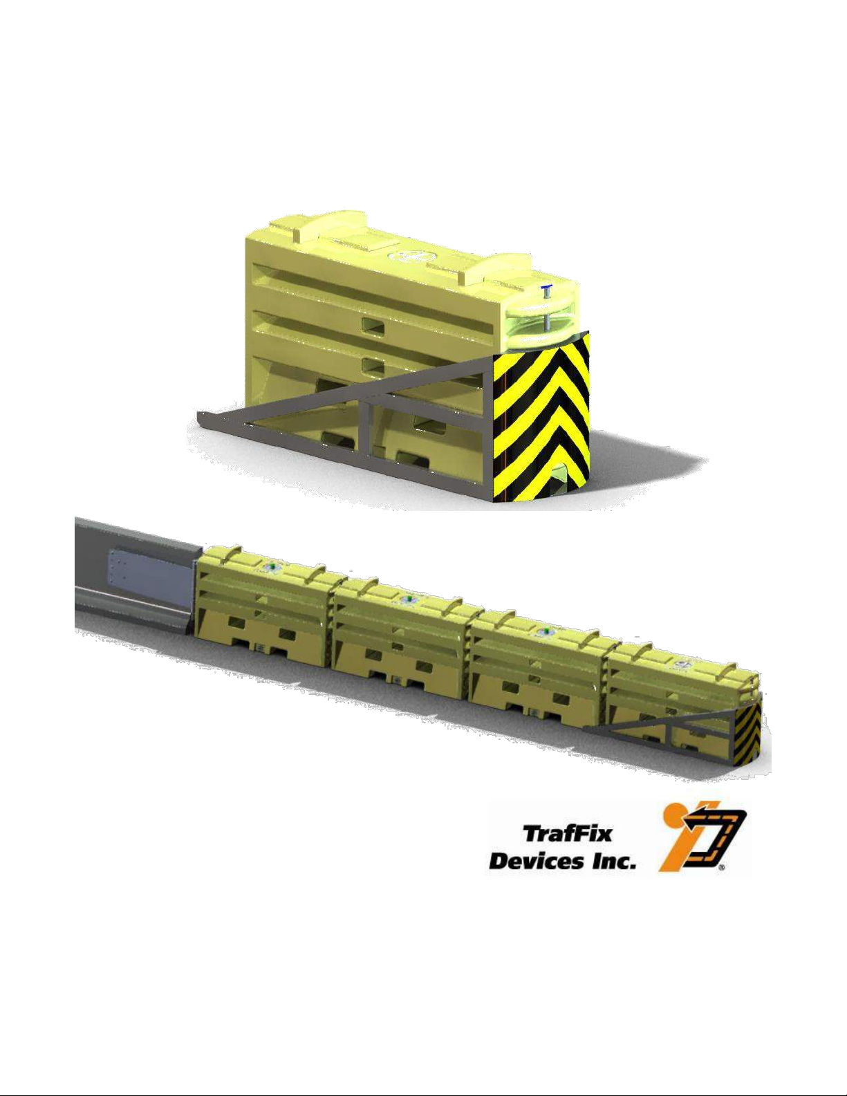
SLED End Treatment System
Manual
160 Ave. La Pata
San Clemente, California 92673
(949) 361-5663
FAX (949) 361-9205
www.traffixdevices.com
PN 45045 Revision E (Dated 11/26/12)
Page 2

Table of Contents
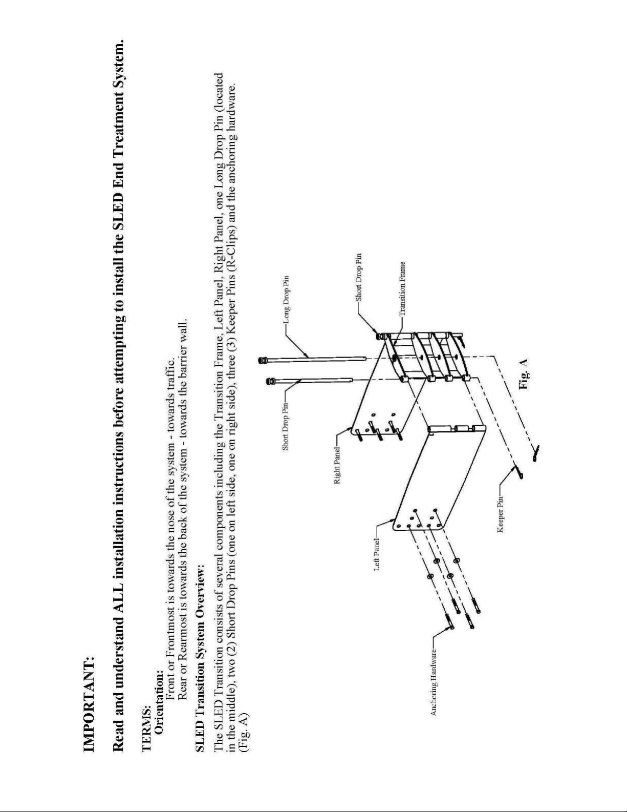
IMPORTANT:
Read and understand ALL installation instructions before
attempting to install the SLED End Treatment System.
Page
Limitations and Warnings ................................................................................................................ 1
Safety Precautions ........................................................................................................................... 2
System Overview…………………………………………………………………………….…… 3
Product Overview and Function ...................................................................................................... 4
SLED Identification and Orientation .............................................................................................. 5
Product Components and General Specifications ............................................................................ 6
Directional Application Definition ................................................................................................ 11
Speed Configuration ..................................................................................................................... 12
Recommendations for Stacking ..................................................................................................... 13
Installing SLED Nose Sheeting ..................................................................................................... 14
Water Freezing Prevention ............................................................................................................ 15
Tools and Equipment for Assembly and Installation .................................................................... 17
SLED End Treatment System Installation ..................................................................................... 18
Appendix A: SLED End Treatment System Specifications .......................................................... 34
Appendix B: Drawings .................................................................................................................. 37
Appendix C: FHWA Product Acceptance Letter………………………………………………... 55
Appendix E: Regional Sales Managers, Key Contacts, and Customer Service ………………... 57
160 Ave. La Pata
San Clemente, California 92673
(949) 361-5663
FAX (949) 361-9205
www.traffixdevices.com
Page 3

Limitations and Warnings
TrafFix Devices Inc., in compliance with the National Cooperative Research Highway Program 350
(NCHRP350) recommended procedures for safety performance evaluation of highway features,
contracted the services of an approved ISO certified independent test facility, to conduct crash tests,
report findings, and provide complete testing evaluation reports.
The SLED End Treatment System is accepted by the Federal Highway Administration (FHWA) for
use on the National Highway System. TL-3 and TL-2 meet the NCHRP 350 requirements, using the
test impact vehicles that range from light weight cars of approximately 820 kg (1800 lbs), to full-size
pick up trucks of approximately 2000 kg (4400 lbs).
A series of inline, offset, side and angle impacts at a designated speed of 100 kph (62.1 mph) were
conducted to verify the SLED’s impact performance. All Occupant Risk Values were deemed a
PASS per NCHRP 350 specifications.
The SLED End Treatment System is designed to be installed and maintained in accordance with the
recommendations and guidelines of the governing state and FHWA.
After an impact, damaged components should be removed and replaced with new components.
Revision E (Dated 11/26/12) 1
Page 4

Safety Precautions
CAUTION
Before handling any TrafFix Devices product always be sure to wear
proper protective equipment including:
SAFETY EYEWEAR
STEEL TOE BOOTS SAFETY VEST
HARDHAT
HEARING PROTECTION
GLOVES
Revision E (Dated 11/26/12) 2
Page 5
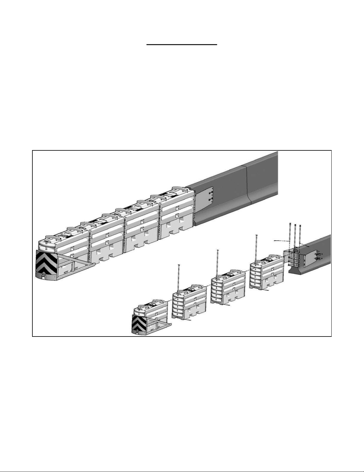
System Overview
The SLED End Treatment System is a gating, non-redirective crash cushion designed to shield the
end of permanent and portable barriers made of concrete, steel, or plastic. The SLED End Treatment
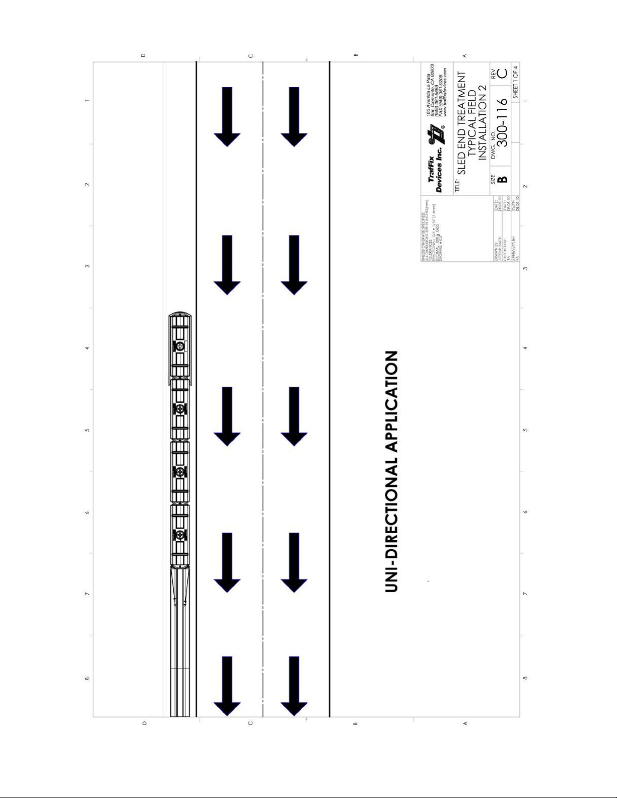
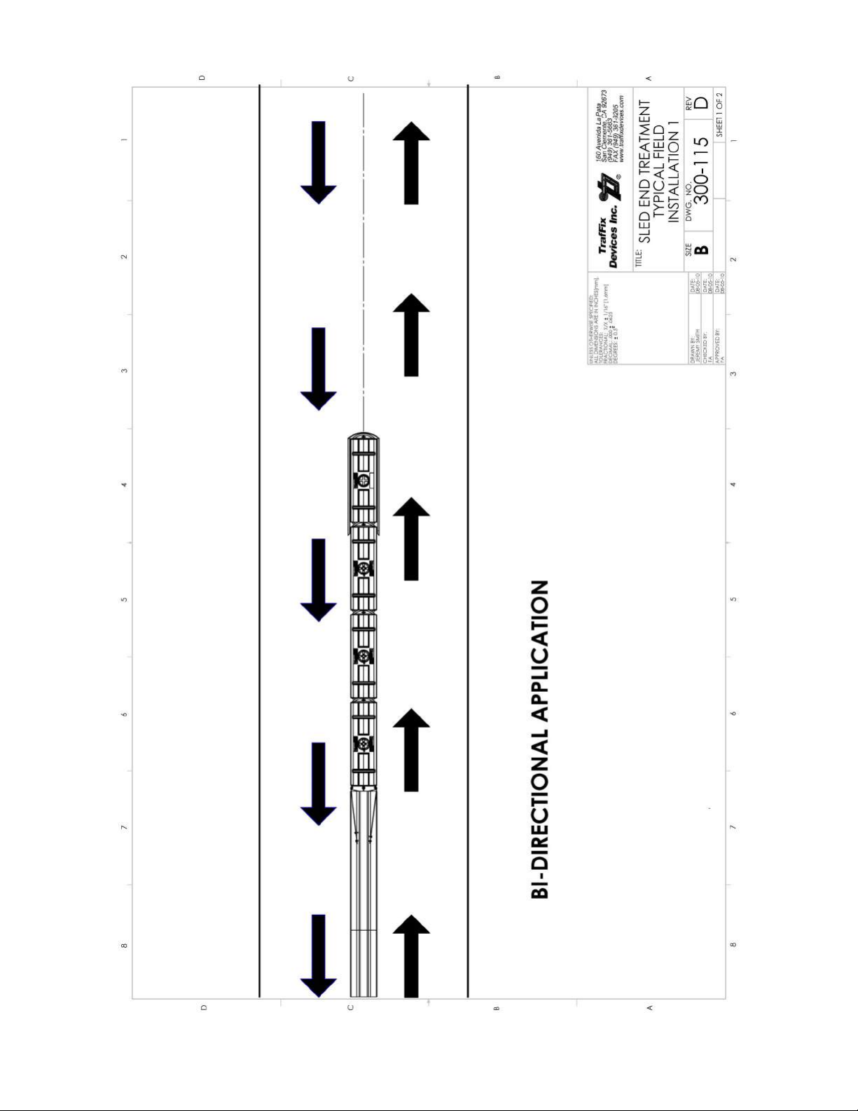
System is designed for uni– and bi-directional traffic flow applications (or on pp. 47-48).
Crash Performance
The SLED End Treatment Modules are yellow in color. The NCHRP 350 Test Level 3 (TL-3)
System has an overall length of 26 ft (7.92m) long and is 1.875 ft (0.57m) wide. The NCHRP 350
Test Level 2 (TL-2) System has an overall length of 18.9375 ft (5.77m) long and is 1.875 ft (0.57m)
wide. Each Module has overall dimensions of approximately 6.3 ft (1.93m) x 1.875 ft (0.57m) x 3.8
ft (1.16m) and weighs approximately 160 lbs empty and 2000 lbs full.
Figure 1: TrafFix Devices SLED End Treatment System shown in TL-3 configuration.
Revision E (Dated 11/26/12) 3
Page 6

Product Overview and Function
The SLED End Treatment System is a water filled gating non-redirective crash cushion designed to
shield permanent and portable barriers. The TL-3 SLED End Treatment System consists of three water
filled and one empty plastic modules to produce the desired energy attenuation characteristics to
decelerate an impacting vehicle to meet TL-3 crashworthy requirements of Report NCHRP 350.
Attached to the front empty module is the patented Containment Impact Sled (CIS) which collects the
ruptured debris in front of the impacting vehicle..
Additional Features:
NCHRP 350 TL-3 and TL-2 Tested – Accepted for use on the National Highway System as a
TL-3, Crash Cushion, CC-114 and a TL-2, Crash Cushion, CC-117.
Overall TL-3 array length is 26 ft (7.92m) and TL-2 array length is 18.9375 ft (5.77m) long.
Acceptable for Permanent and Portable installations.
Attaches to various barrier shapes made of concrete, steel, or plastic.
All metal components are domestic sourced steel in accordance with Buy America requirements.
Does not require any external steel for module assembly.
Rotational molded plastic, modules are manufactured from specially formed material
designed to be durable when handled and attenuate when impacted.
Module sections up to ½” (14 mm) thick reduce nuisance hit damage and the potential for
vandalism.
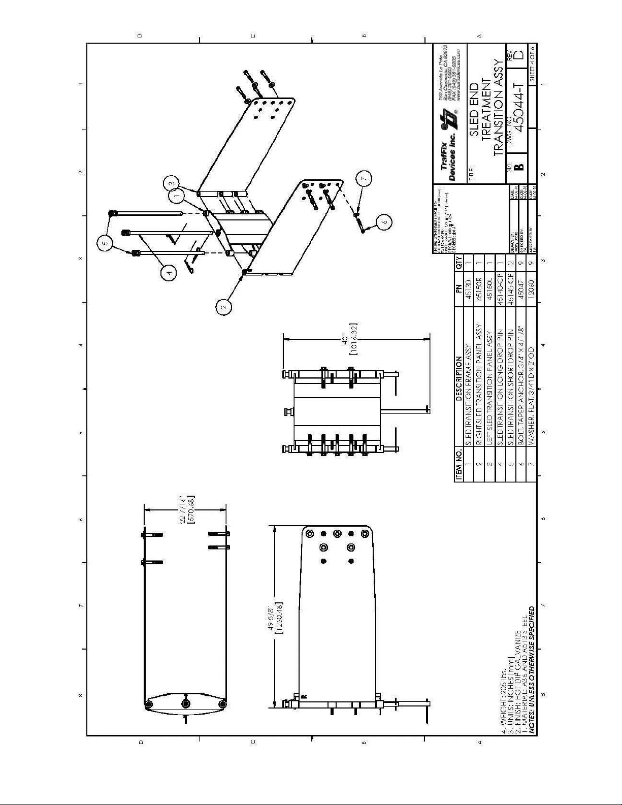
Designed for use in uni– or bi-directional traffic flow applications.
Revision E (Dated 11/26/12) 4
Page 7
SLED Identification and Orientation
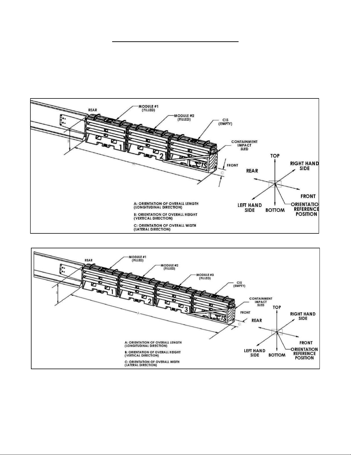
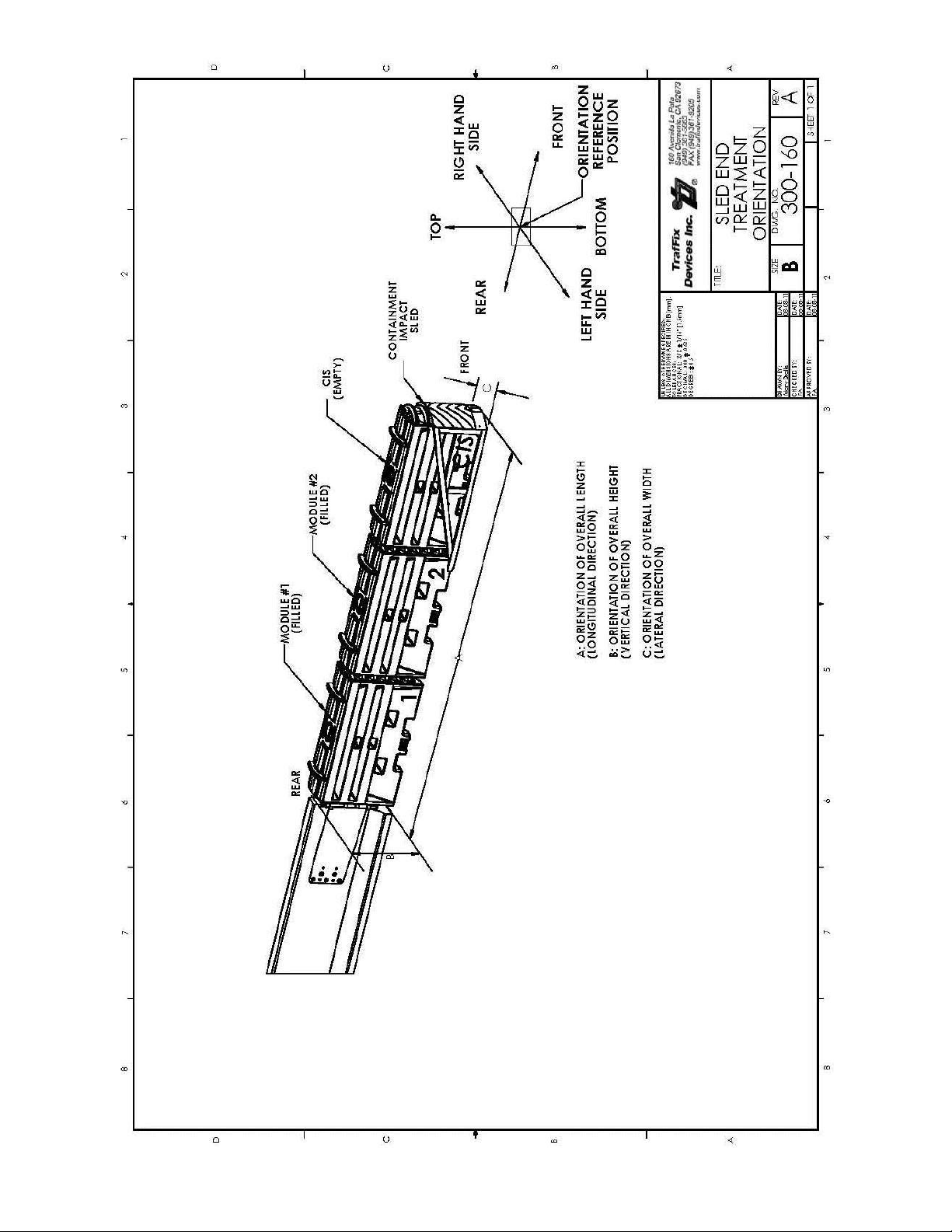
Figure 2 (or on pg. 38) identifies the TL-2 SLED End Treatment Systems front and rear orientation
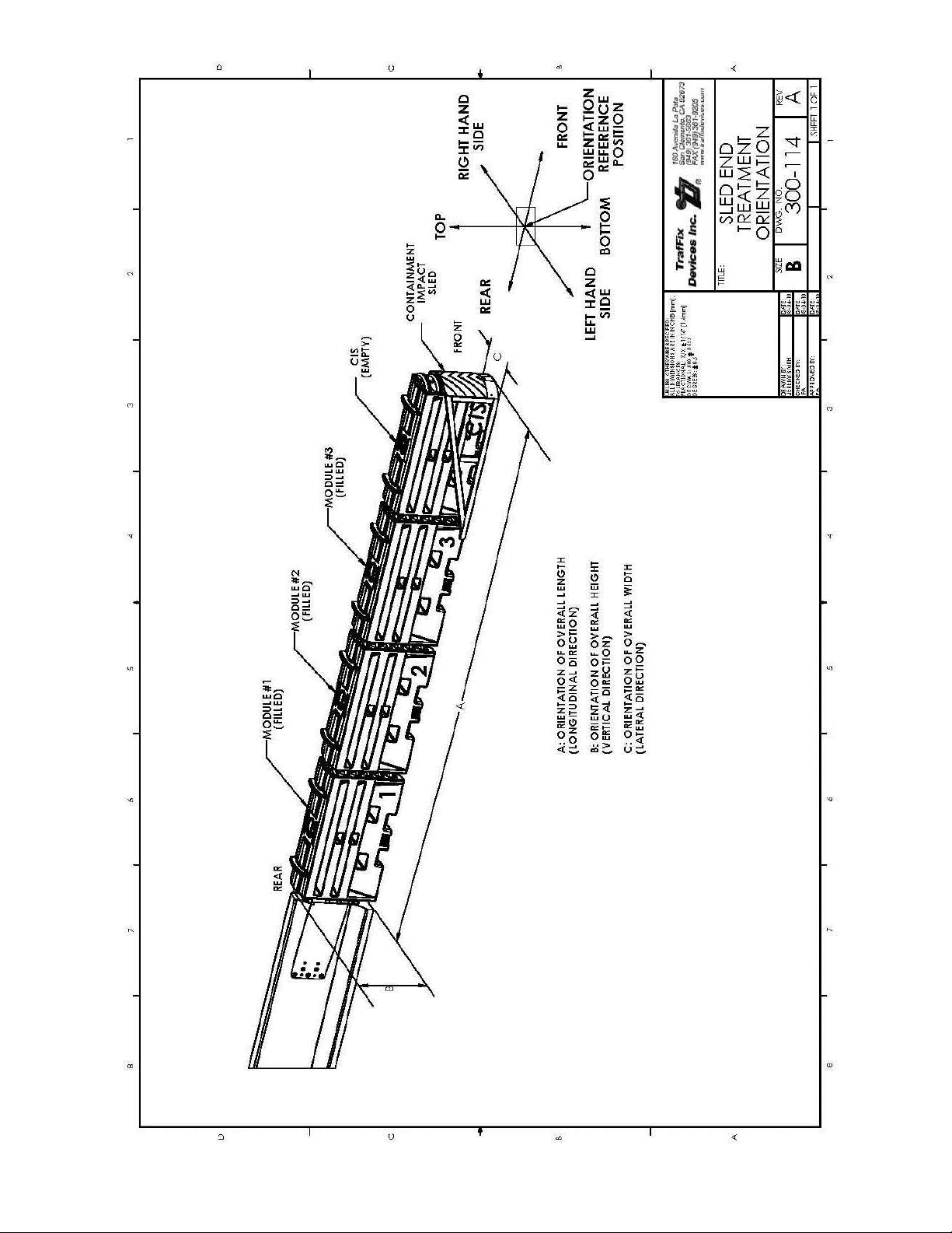
for installation. Figure 3 (or on pg. 39) identifies the TL-3 SLED End Treatment Systems front and
rear orientation for installation. The Containment Impact Sled orients the front. Module #1 attached
to the shielded barrier orients to the rear. This same configuration can be used in uni- or
bi-directional traffic flow applications.
Figure 2: TL-2 SLED End Treatment Orientation.
Figure 3: TL-3 SLED End Treatment Orientation.
Revision E (Dated 11/26/12) 5
Page 8
Product Components and General Specifications
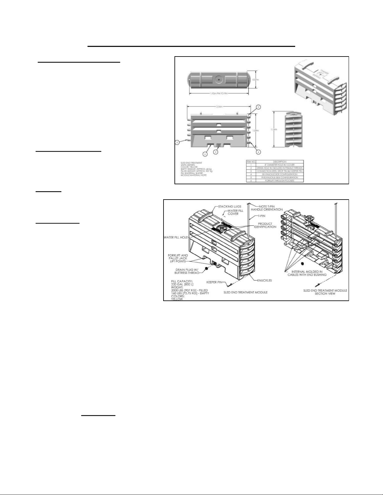
Module Specifications
All SLED End Treatment System
Modules are yellow in color and have an outer shell made from energy attenuating plastic. The modules will collapse and
rupture when impacted and disperse the
contained water. The modules will not crack
or corrode when left on the job site or stored
for long periods of time.
Overall Dimensions:
Width: 22½” [571 mm]
Height: 42-11/16” [1084 mm]
Length 75-3/4” [1924 mm] pin to pin
Weight:
Empty Weight: 160 lbs. [73 kg]
Filled Weight: 2000 lbs. [907 kg]
Fill Capacity:
Volume: 220 Gal [832 L]
Each module contains an eight inch
diameter water fill-hole located on the
top surface of each module section. This
large diameter opening allows for easy
access for water filling using a large
diameter hose from a water tanker truck.
Each module comes with a twist lock
lid to cover the fill hole opening when
the water filling process is complete. A
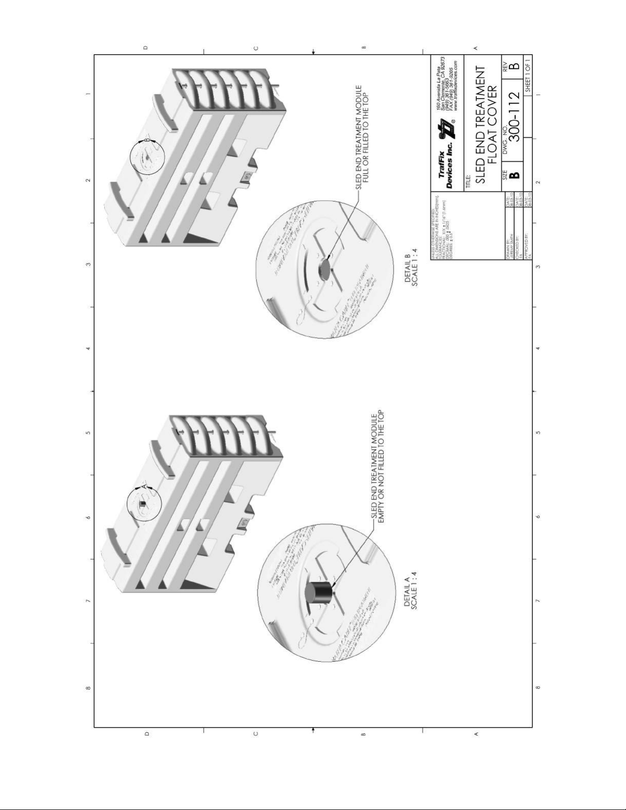
water level indicator is designed into the twist lock lid. Figure 6 (or on pp 7 and 52) .
For draining, a central drain hole is located at the bottom of each module. Each drain hole contains
molded-in Buttress threads. The drain plug requires 1-1/2 turns to seal the plug preventing any water
leaks. The molded-in Buttress threads eliminate the possibility of cross threading compared to standard
threads used in a spin welded insert. Cracked spin welded inserts may require repair and are typically
not reliable, leading to water leaks. The SLED Modules, with molded in Buttress threads, eliminates
both issues of cross threading and insert repair.
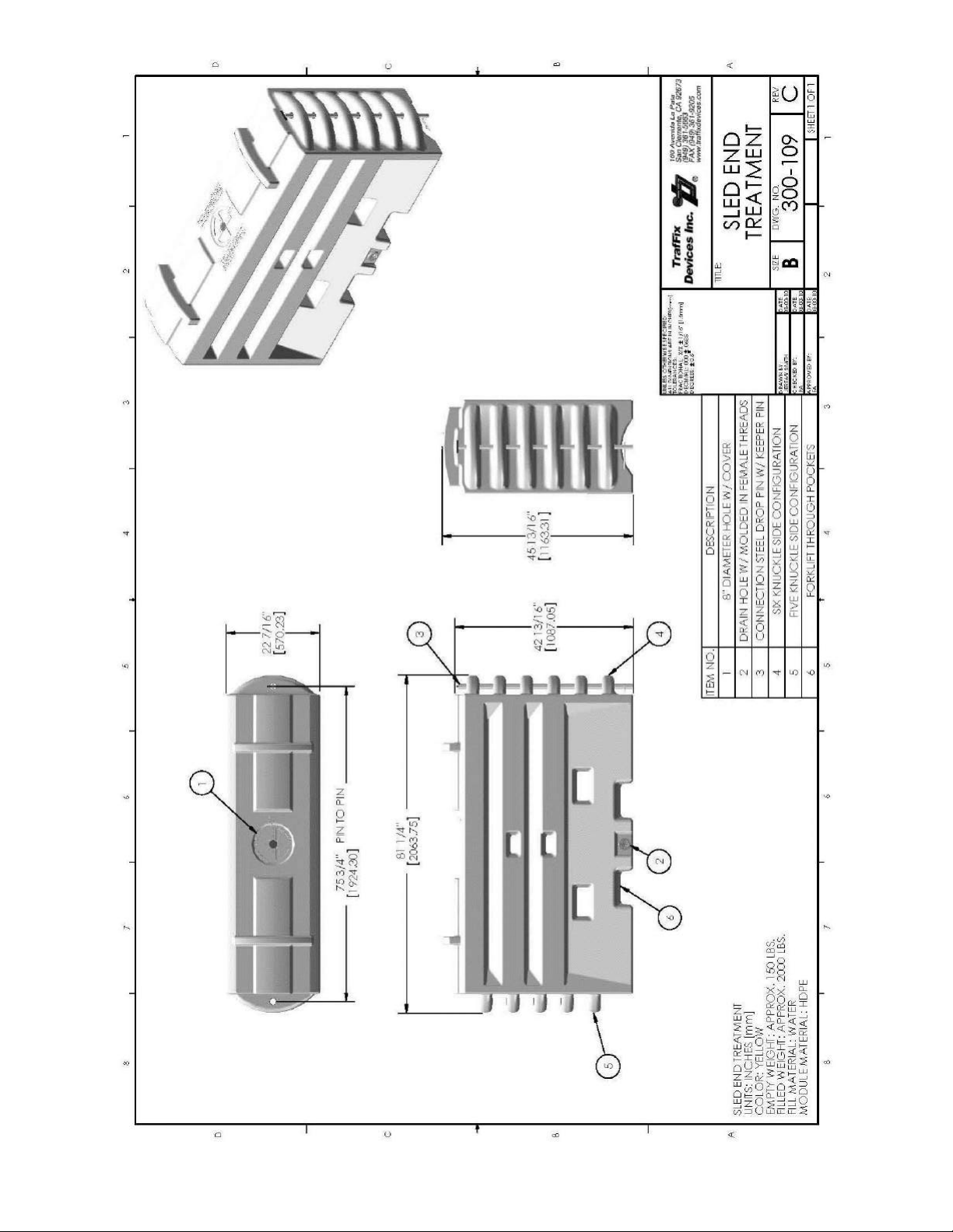
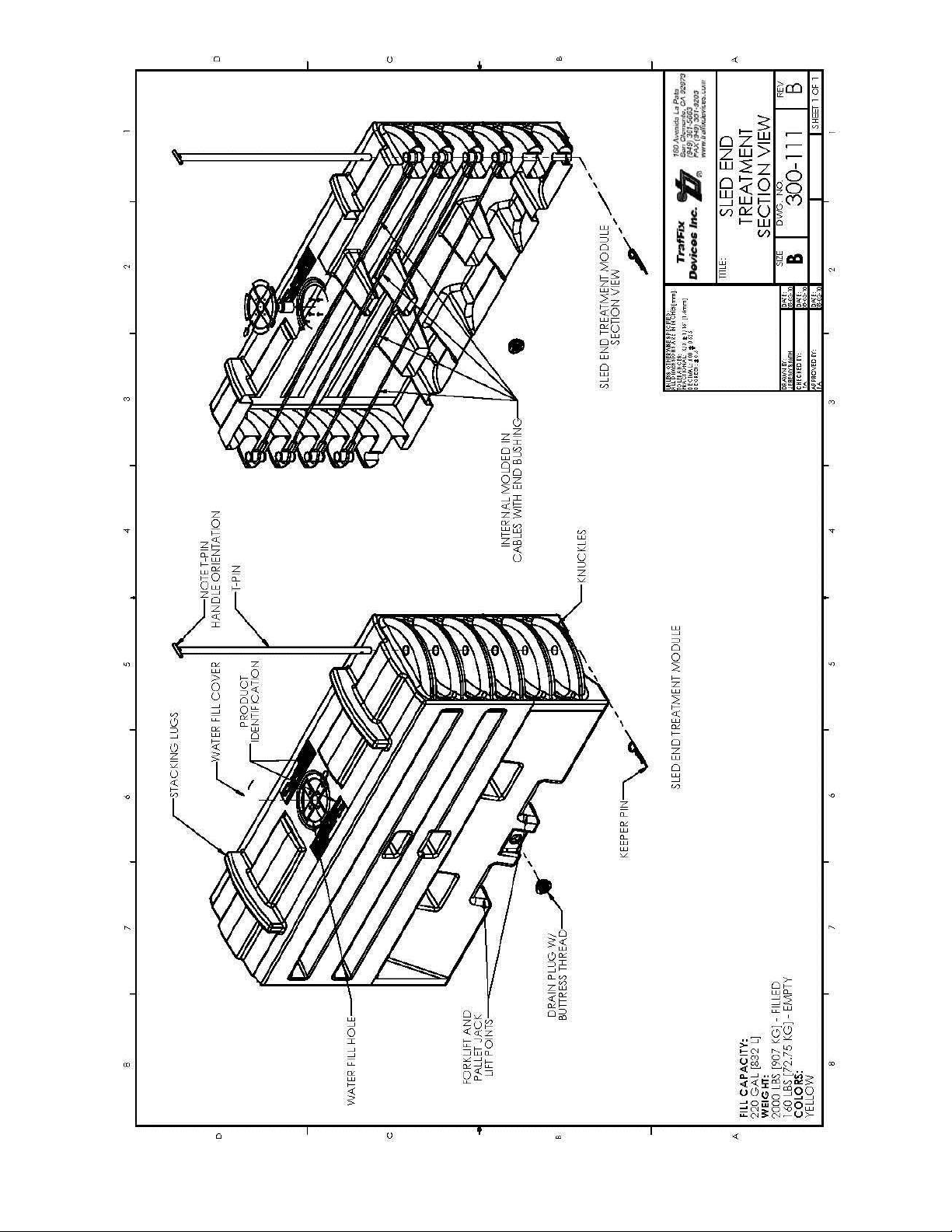
Two forklift pockets (slots) are designed into the modules, located at grade level, which can be used to
insert forklift blades for moving the filled or unfilled SLED Modules sections as needed. The molded-
in steel cables ARE NOT be to be used for lifting the modules. Only the two forklift pockets
(slots) should be used to lift the modules as identified in Figures 4 and 5 (or on pp. 40 and 41).
Figure 4: Module details.
Figure 5: Module details.
Revision E (Dated 11/26/12) 6
Page 9
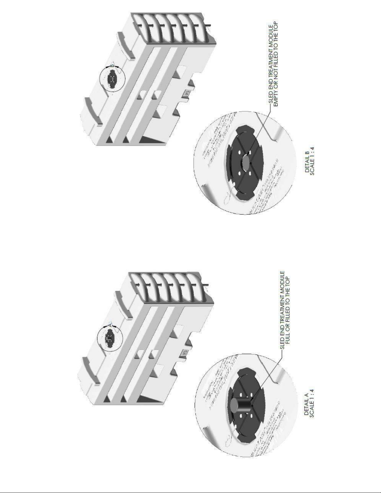
Water Level Indicator Fill Cap
Figure 6: SLED End Treatment Module float cover.
Revision E (Dated 11/26/12) 7
Page 10
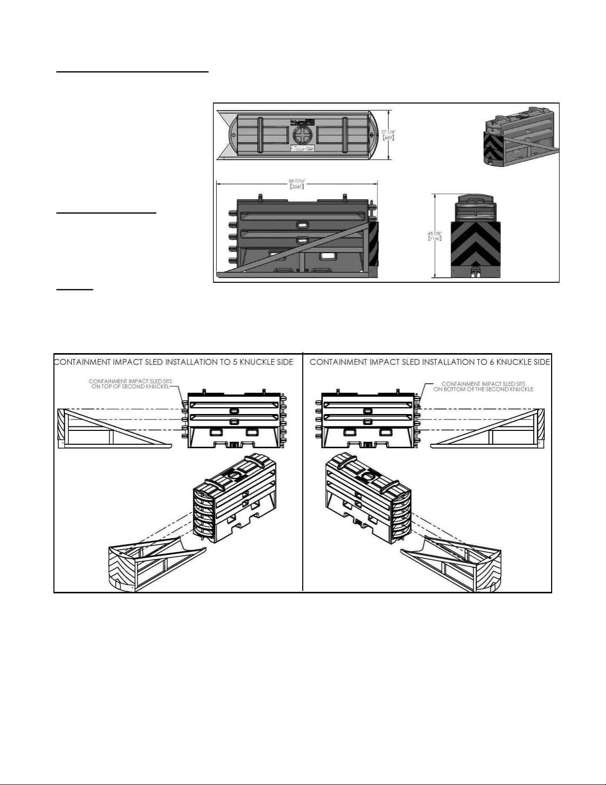
Containment Impact Sled
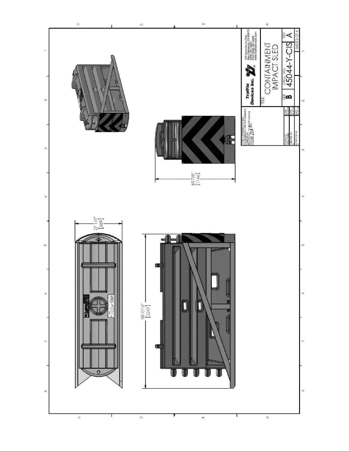
The Containment Impact Sled (CIS) is attached to the front empty module Figure 7 (or on pg 42). The
steel CIS is hot dipped
galvanized to minimize the
affects of corrosion. Upon
impact, the CIS slides rearward
collecting the ruptured modules.
Overall Dimensions:
Width: 27 1/4” [689 mm]
Height: 45 7/8” [1166 mm]
Length: 88 7/16” [2247 mm]
Weight:
Figure 7: SLED End Treatment CIS Module.
Weight: 197 lbs [89 kg]
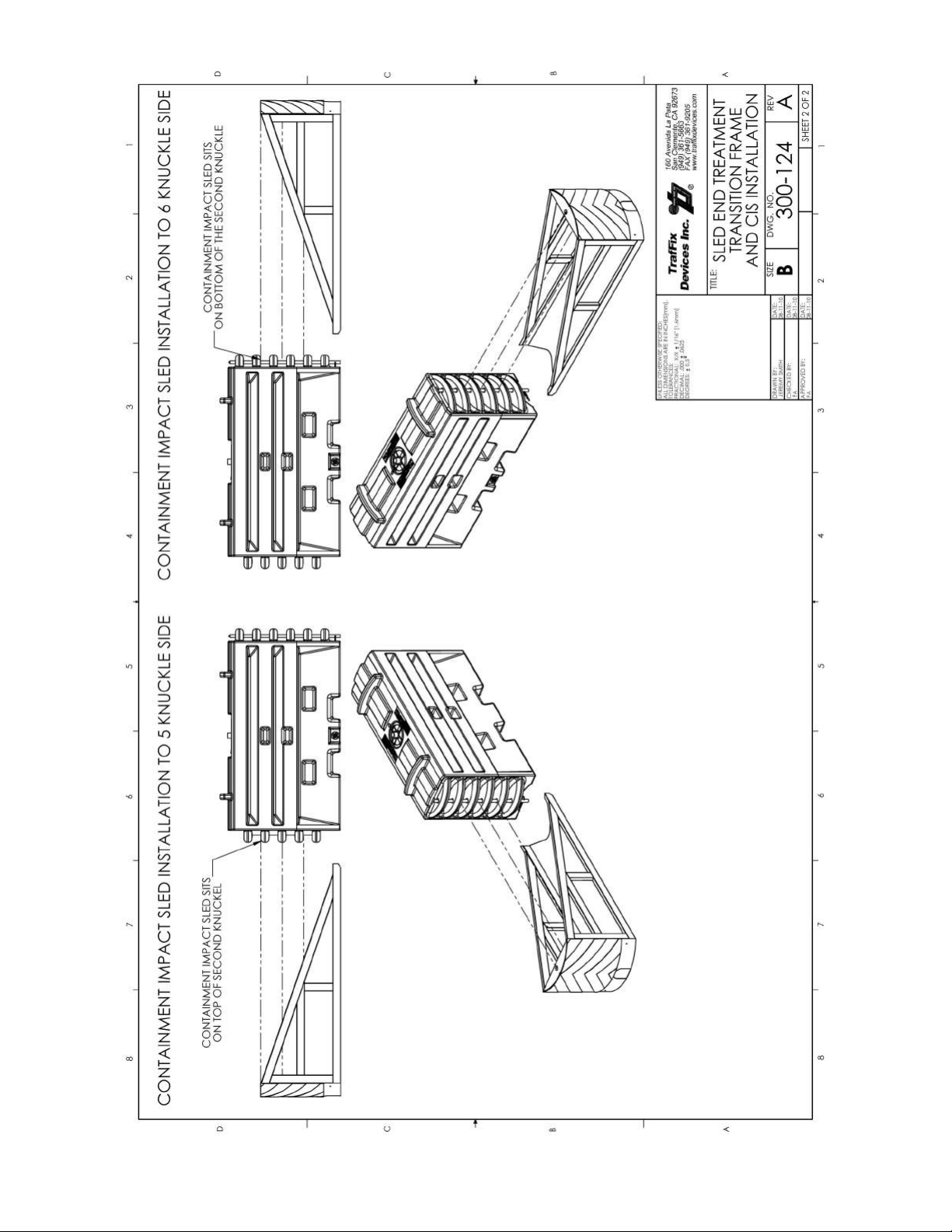
The CIS is tube frame designed with a curved front cap and a flat steel bottom. The CIS is pinned onto
empty No-Fill Module with a vertical T-pin that drops through a series of the concentric holes in the
Figure 8: SLED End Treatment Sled installation to both ends of a module.
Revision E (Dated 11/26/12) 8
Page 11
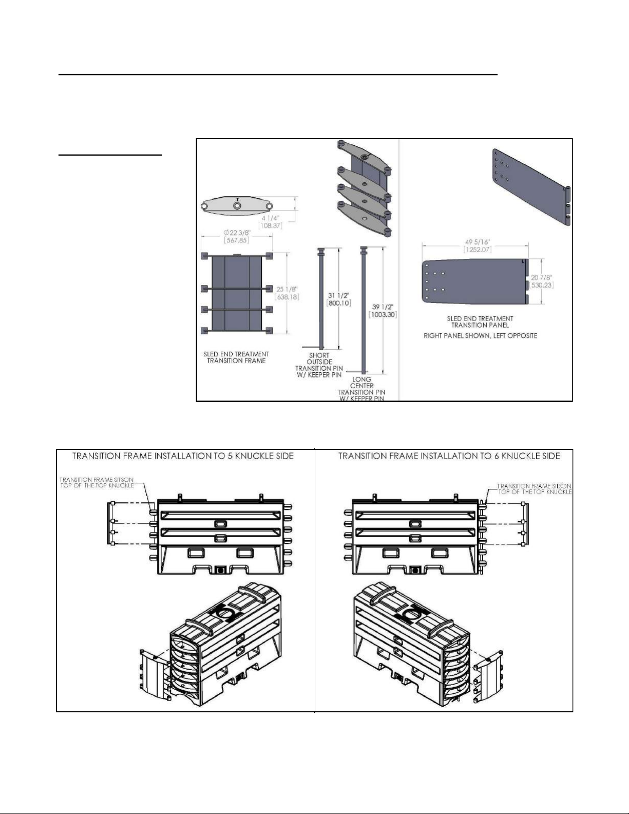
Transition Attachment For Attaching the SLED To An Array or Barrier
The Transition is made from steel sheet and tubing that is hot dipped galvanized to minimize the affects
of corrosion. The Transition attaches to the rear of the SLED system and is fastened to the shielded
barrier with a minimum of eight anchor bolts, with nine bolts preferred.
Overall Dimensions:
Width: 22 3/8” [568 mm]
Height: 20 7/8” [530 mm]
Length: 49 5/8” [1260
mm]
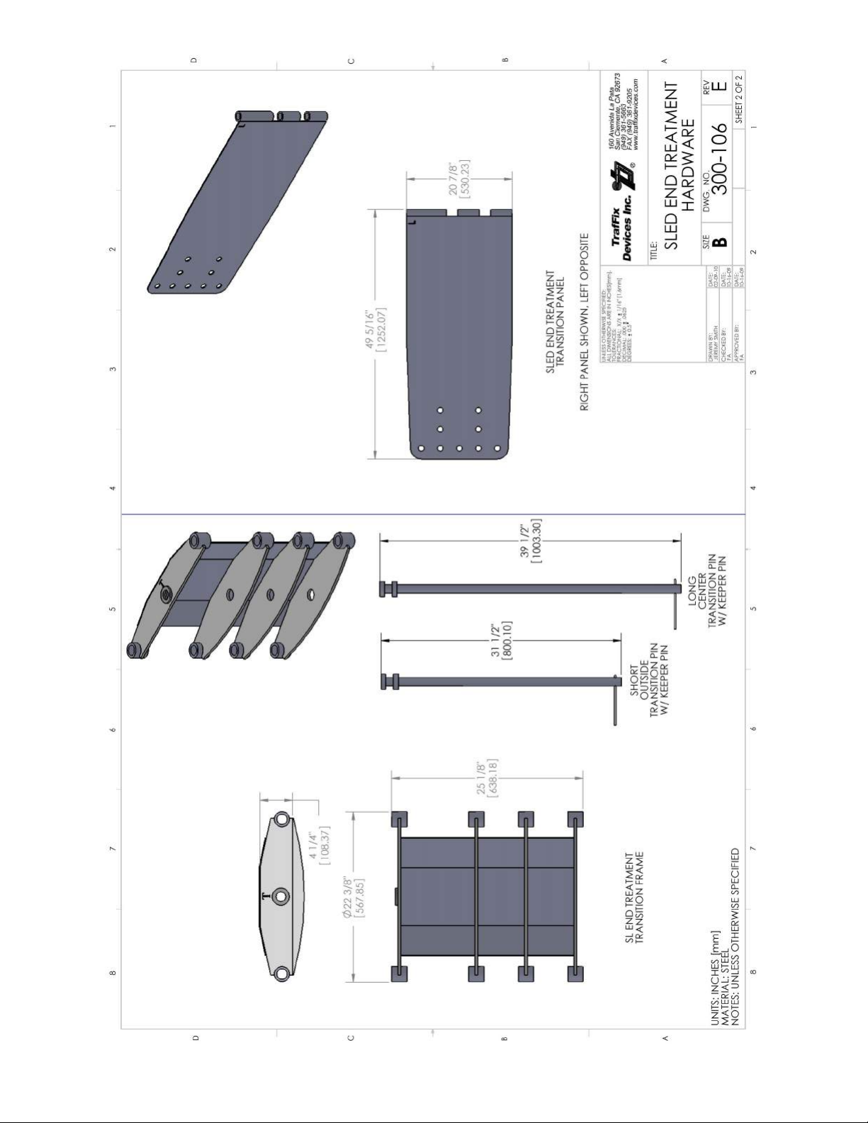
The Transition consists of
a frame, right and left
panels, and connection
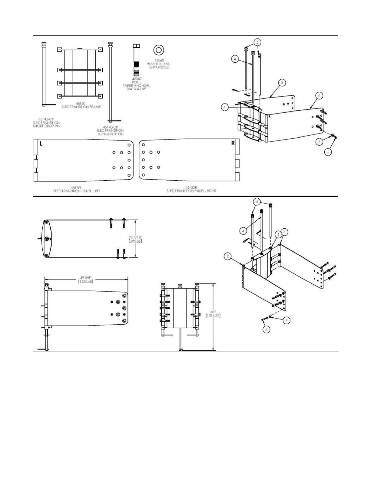
pins. The frame, Figure 9
and 11 (or on pg. 44) is
connected to Module 1.
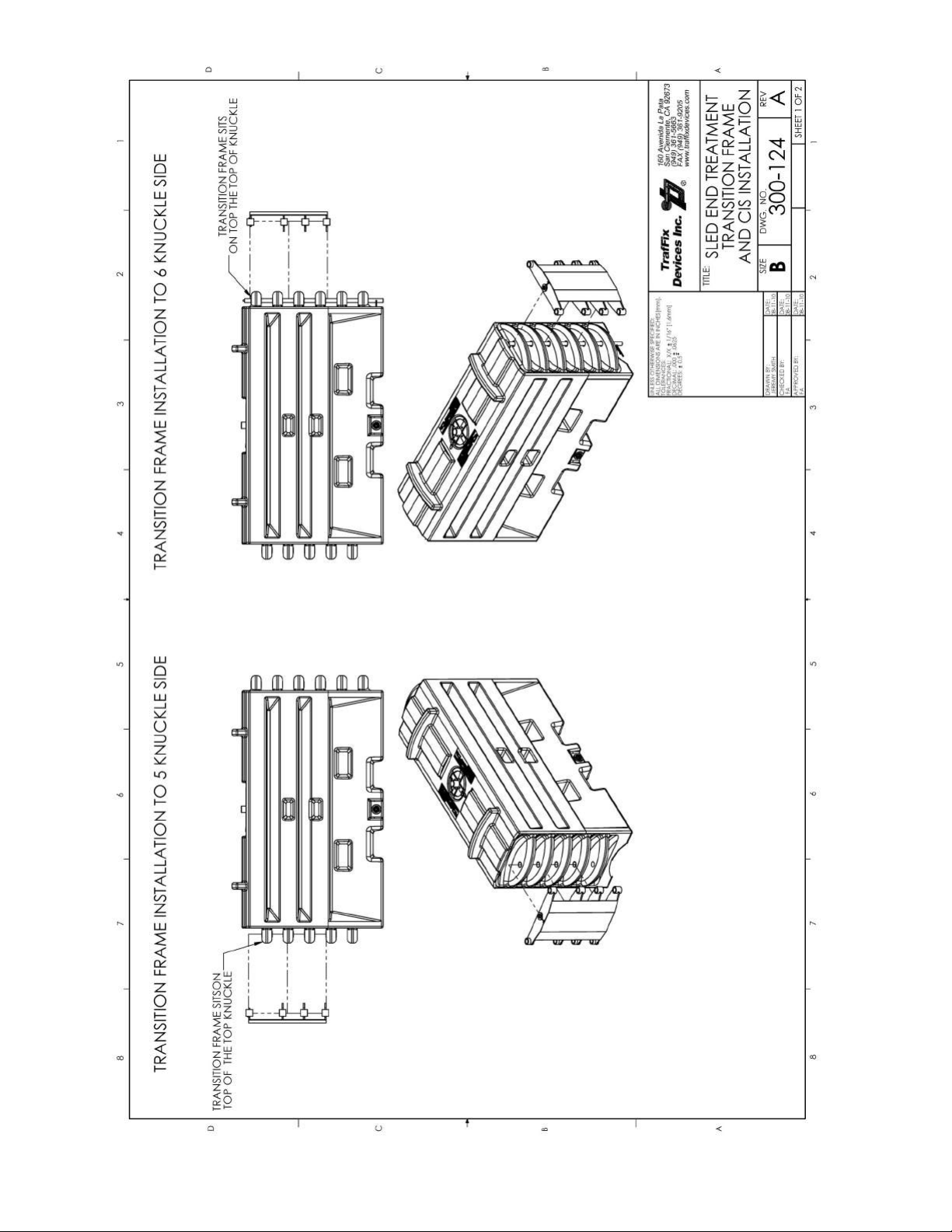
The transition frame is designed to attach to either
the five or six knuckle end
of the rear module, Figure
10 (or on pg. 45).
Figure 9: SLED End Treatment Transition.
Figure 10: SLED End Treatment Transition Frame installation to both ends of a module.
Revision E (Dated 11/26/12) 9
Page 12
L
R
R
Figure 11: Transition Components
Revision E (Dated 11/26/12) 10
Page 13
Directional Application Definition
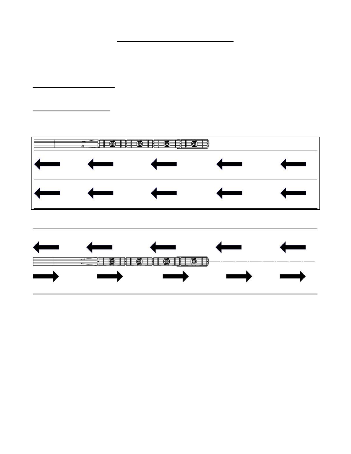
The SLED End Treatment modules are designed for uni– and bi-directional traffic applications where a
gating device is acceptable to the road authority*. A general definition of these applications are
described below and graphically displayed in Figures 12 and 13( or on pp 47 and 48) .
Uni-Directional Application: Uni-directional refers to the flow of traffic in a single direction as seen
in Figure 12. In this type of application opposite direction impacts would not be probable.
Bi-Directional Application: Bi-directional refers to the flow of traffic in both directions typically
referred to as counter flow as seen in Figure 13. In this type of application the counter flow of traffic
could result in a reverse impact into the SLED End Treatment System.
Figure 12: Traffic flow uni-directional application.
Figure 13: Traffic flow bi-directional application.
* Reference FHWA HSST/CC-114
Revision E (Dated 11/26/12) 11
Page 14
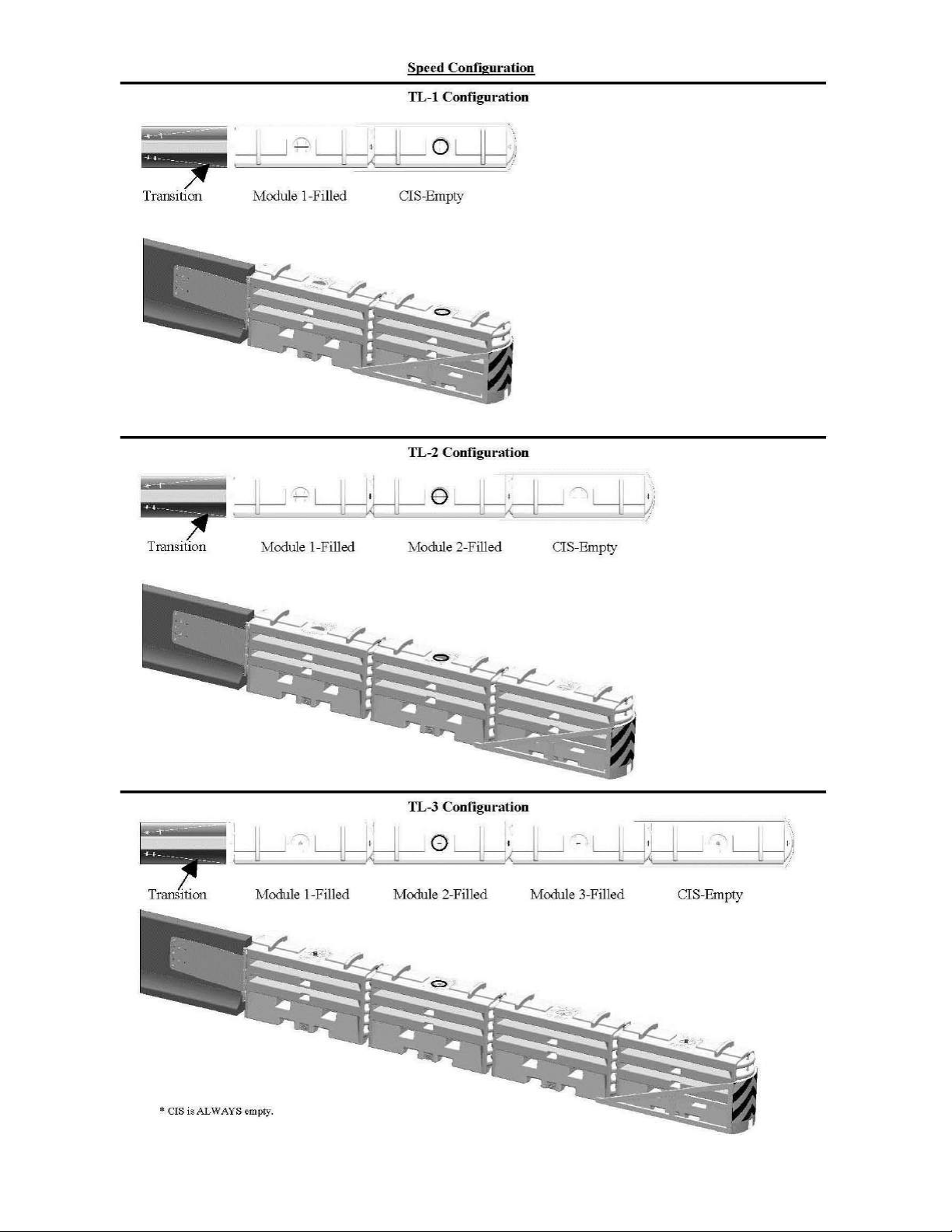
Figure 14: SLED End Treatment Speed Configurations
Revision E (Dated 11/26/12) 12
Page 15
Recommendations for Stacking
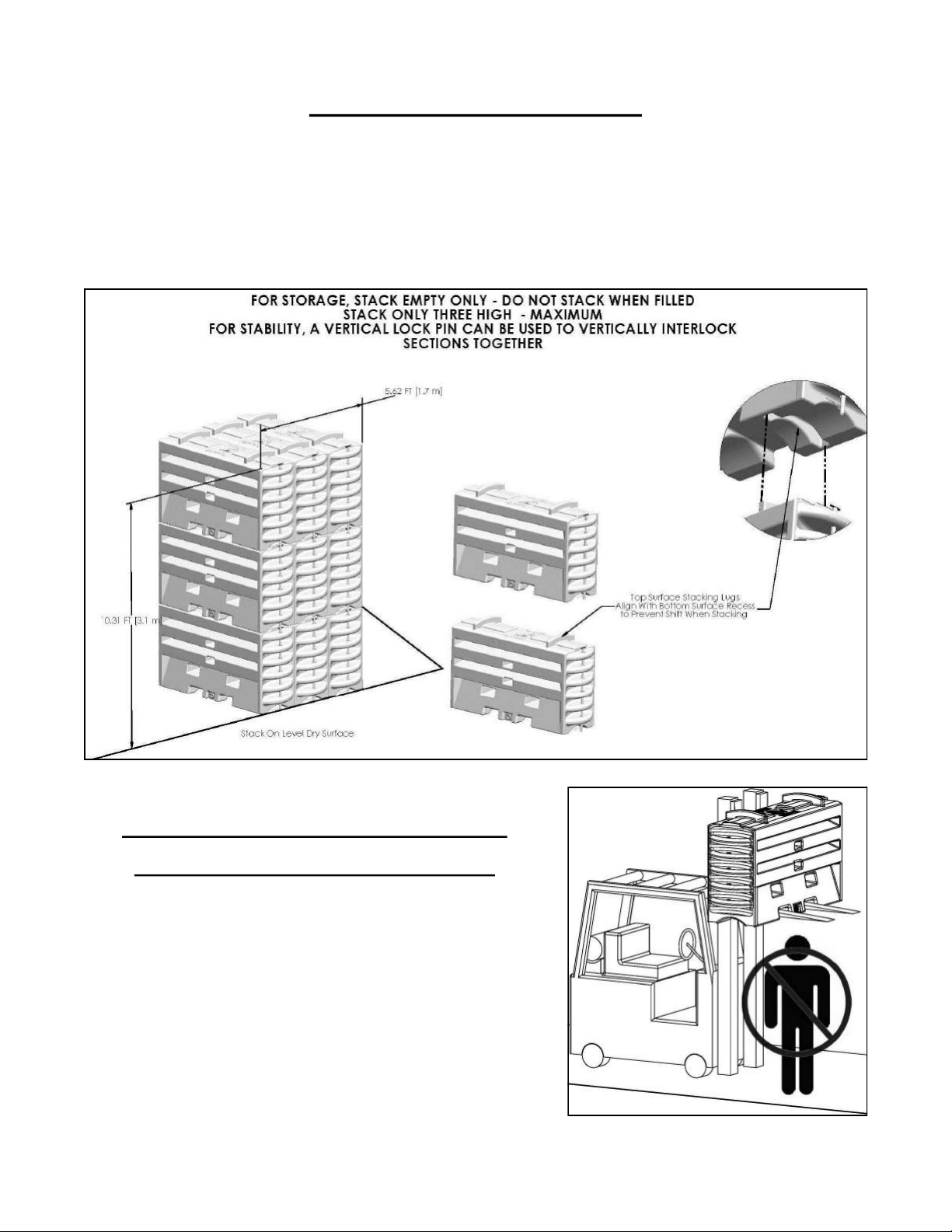
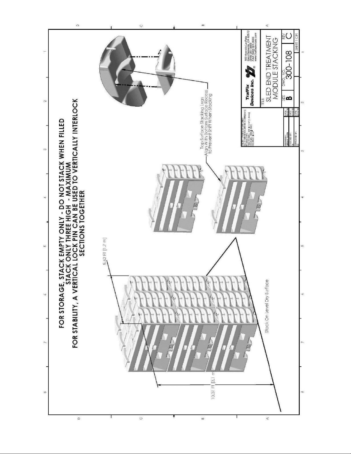
Modules can be stacked ONLY when empty and are not designed to be stacked on each other when
filled. Stacked empty modules can be no more than three high as seen in Figure 15 (or on pg. 49).
Designed into the top surface of each module are stacking lugs which fit into recessed formed sections
on the bottom surface of each module as seen in Figure 15. These stacking lugs interlock the modules
preventing the wall from shifting during transport or storage. The stacking lugs should be used in
conjunction with straps to securely hold the entire stacked pieces together. For additional support, a
long T-pin can be inserted into the knuckles to secure the modules as seen in Figure 15 (or on pg. 49).
Figure 15: Module Stacking Diagram for Long Term Storage Requirements
SAFETY PRECAUTIONS WHEN HANDLING
THE SLED END TREATMENT MODULES
Do not drive with two (2) or more filled modules on a
forklift. If maneuvering filled modules is necessary using
a forklift, only move filled modules one (1) at a time. If
the modules are empty, a maximum of three (3) stacked
modules may be moved using a forklift. NEVER STACK
MODULES WHEN FILLED. And most importantly, do
not stand underneath or in front of the forklift when
handling the modules with a forklift as modules may
fall, see Figure 16.
Figure 16: Proper Forklift Procedure
Revision E (Dated 11/26/12) 13
Page 16
Installing SLED Nose Sheeting
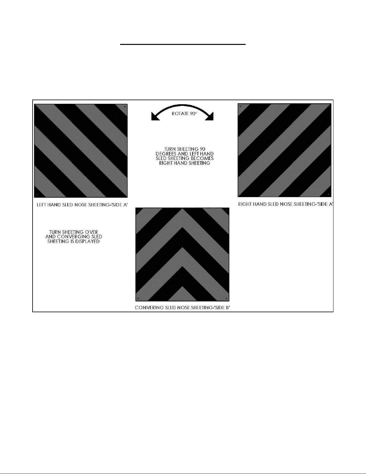
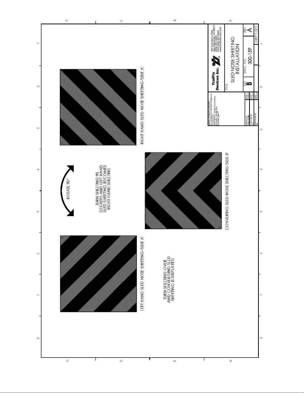
The SLED nose sheeting has been provided in a way to customize field use as seen in Figure 17 (or on
pg. 50). On Side A, the diagonal stripes can but used for Left Hand traffic flow or rotated 90 for Right
Hand traffic flow. Turn the sheeting over and Side B is used for converging traffic flow. Once the
direction is determined, secure the sheeting to the nose with supplied screws.
Figure 17: SLED Nose Sheeting Installation
Revision E (Dated 11/26/12) 14
Page 17

Water Freezing Prevention
In freezing weather conditions, do not allow the water in the SLED modules to freeze to a solid mass
of ice. If the temperature at the SLED site is expected to be at or below the freezing point of water
32° F [ 0°C ], it is recommended that an additive be used to prevent the water in the SLED modules
from freezing. See Table 1 on pg. 16.
-Common additives used to prevent water freezing currently used in work zone devices
under the same category as the SLED Modules.
SALT (Sodium Chloride)
20% mixture by weight
Reduces freezing down to 0° F [-18° C].
Corrosive to inadequately protected steel components (Galvanizing adequately prevents
corrosion)
Recommended - premix before filling
Prevent spilling since solution is harmful to vegetation, soils, and wildlife. Draining should be done
in an acceptable area.
CALCIUM CHLORIDE
35% mixture by weight
Reduces Freezing down to 20° F [ -6.6 °C ].
Corrosive to thin zinc plated components
Corrosive to inadequately protected steel components (Galvanizing adequately prevents
corrosion)
High tendency to stay on road surface resulting in slick road surface.
High level of heat created when mixing. It is recommended that pre-mixing is done before filling.
Prevent spilling since solution is harmful to vegetation, soils, and wildlife. Draining should be done
in an acceptable area.
ETHYLENE/PROPYLENE GLYCOL
50% mixture by volume
Reduces water freezing to 0° F [-18° C].
High tendency to stay on road surface resulting in slick road surface.
Prevent spilling since solution is harmful to vegetation, soils, and wildlife. Draining should be done
in an acceptable area.
LIQUID CMA (Calcium Magnesium Acetate)
25% mixture by volume
Reduces water freezing to 0° F [-18° C].
Has a low environmental impact.
LIQUID POTASSIUM ACETATE
60% mixture by volume
Reduces water freezing to 20° F [-6.6° C]
Low corrosive characteristics and has a low environmental impact.
Revision E (Dated 11/26/12) 15
Page 18

Table 1- Recommended water freezing prevention chart solution comparison.
Environmental
Additive
Salt (Sodium Chloride) Harmful Low 0 °F [-18 ° C] 20% by weight
Calcium Chloride Harmful Medium 20 °F [-6.6 ° C] 35% by weight
Ethylene/Propylene Glycol Dangerous High 0 °F [-18 ° C] 50% by volume
Liquid CMA Non-Toxic High 0 °F [-18 ° C] 25% by volume
Liquid Potassium Acetate Non-Toxic High 20 °F [-6.6 ° C] 60% by volume
Impact Cost Rating Protection Temp Mix Solution Ratio
Revision E (Dated 11/26/12) 16
Page 19

Tools and Equipment for Assembly and Installation
This list of tools is a recommendation. The actual tools required will depend on site
conditions for the assembly and installation. Personal protective equipment should always be
used during assembly and installation. Safety eyewear, steel toe boots, hard hat and gloves are
recommended as protection devices for the installer’s safety.
Documents:
Before the assembly and installation of this product, it is recommended that the complete manufactures
manual and drawing package be reviewed for clarity of the installation.
Tools:
Concrete Hole Drilling Tools: (Suggestions Would Be)
-Two Fluted Concrete Drill Bit 3/4” Diameter (w/ 8” minimum drill length)
-Rebar Cutting Drill Bit 3/4” Diameter (w/ 8” minimum drill length)
-Rebar Eater or Cutter
-Rotational Hammer Drill
Drill bits should be capable of drilling to depths of a minimum of 6 inches into the concrete barrier and
be of good quality to drill through 4000 psi concrete.
Additional Tools:
In addition to hole drilling tools, the following is suggested:
-Electrical Generator (5 kW) and Air Compressor (100 psi)
-Torque Wrench 200 ft-lbs min
-Impact Wrench 1/2” Drive
-Sockets 1/2” Drive 3/4”-2” Nut and Bolt Size Shallow and Deep Sockets
-Ratchet and Extensions 1/2” Drive
-Adjustable Wrench 12”
-Pry/Breaker Bars
-Sledge and Ball Peen Hammers
-Chalk Line
-Concrete Marking Pencil
-Tape Measure
Optional Tools:
Tools that may also be needed: Grinder, Hacksaw, or Torch
Revision E (Dated 11/26/12) 17
Page 20
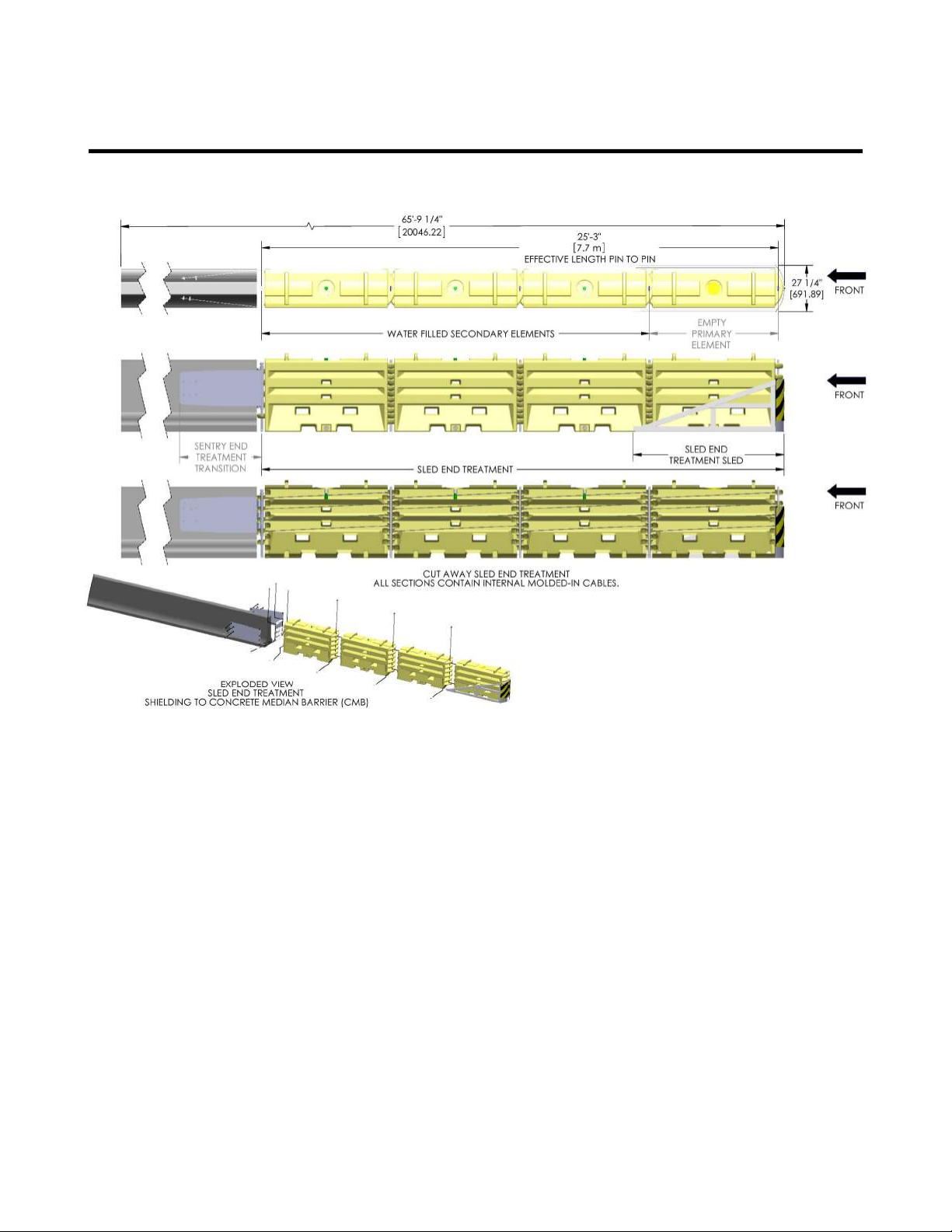
SLED End Treatment System Installation
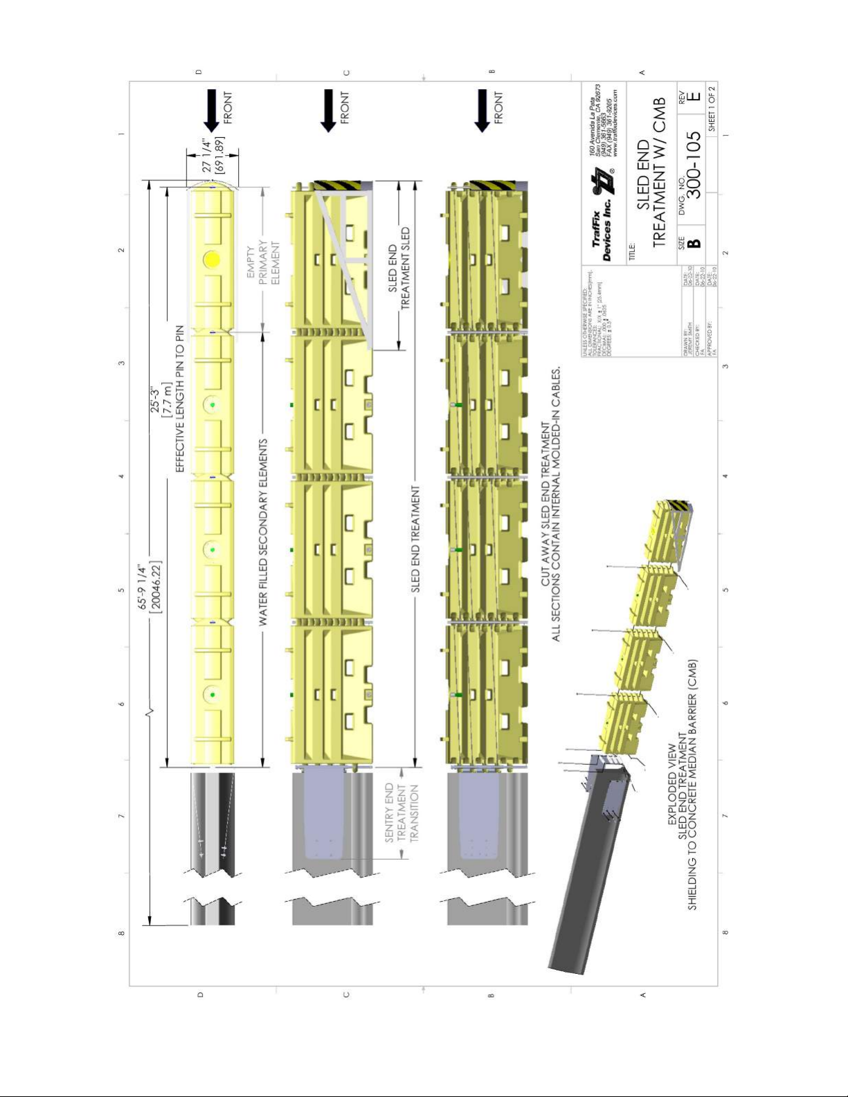
Figure 18: General specifications of installed TL-3 SLED End Treatment system with Transition (or on pg. 51).
Installation procedure to begin on next page
Revision E (Dated 11/26/12) 18
Page 21
Revision E (Dated 11/26/12) 19
Page 22
Revision E (Dated 11/26/12) 20
Page 23
Revision E (Dated 11/26/12) 21
Page 24
Revision E (Dated 11/26/12) 22
Page 25
Revision E (Dated 11/26/12) 23
Page 26
Revision E (Dated 11/26/12) 24
Page 27
Revision E (Dated 11/26/12) 25
Page 28
Revision E (Dated 11/26/12) 26
Page 29
Revision E (Dated 11/26/12) 27
Page 30
Revision E (Dated 11/26/12) 28
Page 31
Revision E (Dated 11/26/12) 29
Page 32
Revision E (Dated 11/26/12) 30
Page 33
Revision E (Dated 11/26/12) 31
Page 34
Revision E (Dated 11/26/12) 32
Page 35
Revision E (Dated 11/26/12) 33
Page 36

Appendix A:
SLED End
Treatment
Specifications
160 Ave. La Pata
San Clemente, California 92673
(949) 361-5663
FAX (949) 361-9205
www.traffixdevices.com
Revision E (Dated 11/26/12) 34
Page 37

I. General
The SLED End Treatment, components, and subassemblies shall be designed and
manufactured by TrafFix Devices Inc. (TDI)
Corporate Office San Clemente, California
Manufacturing & Distribution Center, San Clemente, California
II. System Description
The SLED End Treatment is TL-3 gating non-redirective crash cushion designed to meet
crashworthy requirements of Report NCHRP-350. The SLED End Treatment System shall be
used in permanent and portable installations.
The TrafFix SLED End Treatment shall be constructed from a series of individually linked
modules. Each individual module shall consist of:
Virgin high density polyethylene (HDPE) plastic shell, containing UV stabilizers and
antioxidants molded to a triple faced profile of a ribbed saw tooth shape, designed to
reduce penetration, vaulting, and under riding. Each full length saw tooth ribbed surface
contains a flat surface to adhere a reflective sheeted section.
Designed into each top surface shall be two stacking lugs which assemble into two
recessed voids on the bottom surface. This feature locks the sections together vertically
and prevents shifting during transport or when stored.
The ends of each module shall be constructed with vertically aligned knuckles which
interlock with those of adjacent module and accept a 1⅛ inch [28.58mm] diameter steel
connecting T-pin. The T-pin is retained after installation by a keeper pin.
Each module shall contain four internal molded-in corrosion resistant wire rope cables
acting as a cable barrier when impacted. Each wire rope is connected to a corrosion
resistant steel bushing which is molded into the knuckle sections and contains corrosion
resistant surfaces and is of appropriate diameter to meet design speeds of TL-3 impacts.
The approximate dimensions, weight, and volume of each module shall be: 22.5 in. [571
mm] width x 42 11/16 in. [1084 mm] height x 75 3/4 in [1924 mm] length (pin to pin).
Empty weight 160 lbs [72.6 kg], weight filled 2000 lbs [907 kg], water ballast 220 gal
[832 L].
Modules shall be manufactured in yellow color.
Each module shall be manufactured with fork lift openings to allow for lifting when emp-
ty or full.
Each module shall be manufactured with one 8 in. [203.2 mm] dia. twist lock fill lid and a
2.25 in. [57.15 mm] dia. molded-in Buttress threaded drain hole with a plug to allow quick
water ballast draining.
TrafFix Devices Inc.
TrafFix SLED End Treatment
TL-3 General Specifications
Revision E (Dated 11/26/12) 35
Page 38

III. Performance Criteria
The SLED End Treatment shall be tested and pass all test requirements of Report NCHRP-350
for Test Level 3 (TL-3) impact conditions for 820 kg and 2000 kg [1808 and 4500 lbs] vehicles
at speeds of 100 km/h [62.5 mph].
The SLED test results shall demonstrate that a water filled gating non-redirective crash cushion
shall safely decelerate the 820C and 2000P impact vehicles and shall not exceed the maximum
allowable occupant risk values.
Occupant impact velocity
Maximum allowable:12 m/s for occupant
Ride down acceleration
Maximum allowable: 20 G
Detached debris shall not show potential for penetrating the vehicle occupant
compartment or present a hazard to other traffic, pedestrians, or workers in a work zone.
A vehicle impacting the TrafFix SLED End Treatment shall remain upright during and after the
collision.
The impacting vehicle’s intrusion into adjacent traffic lanes shall be minimized.
Revision E (Dated 11/26/12) 36
Page 39

Appendix B:
Drawings
160 Ave. La Pata
San Clemente, California 92673
(949) 361-5663
FAX (949) 361-9205
www.traffixdevices.com
Revision E (Dated 11/26/12) 37
Page 40
Revision E (Dated 11/26/12) 38
Page 41
Revision E (Dated 11/26/12) 39
Page 42
Revision E (Dated 11/26/12) 40
Page 43
Revision E (Dated 11/26/12) 41
Page 44
Revision E (Dated 11/26/12) 42
Page 45
Revision E (Dated 11/26/12) 43
Page 46
Revision E (Dated 11/26/12) 44
Page 47
Revision E (Dated 11/26/12) 45
Page 48
Revision E (Dated 11/26/12) 46
Page 49
Revision E (Dated 11/26/12) 47
Page 50
Revision E (Dated 11/26/12) 48
Page 51
Revision E (Dated 11/26/12) 49
Page 52
Revision E (Dated 11/26/12) 50
Page 53
Revision E (Dated 11/26/12) 51
Page 54
Revision E (Dated 11/26/12) 52
Page 55
Revision E (Dated 11/26/12) 53
Page 56

Notes
___________________________________________________
___________________________________________________
___________________________________________________
___________________________________________________
___________________________________________________
___________________________________________________
___________________________________________________
___________________________________________________
___________________________________________________
___________________________________________________
___________________________________________________
___________________________________________________
___________________________________________________
___________________________________________________
___________________________________________________
___________________________________________________
___________________________________________________
___________________________________________________
___________________________________________________
___________________________________________________
___________________________________________________
___________________________________________________
___________________________________________________
___________________________________________________
Revision E (Dated 11/26/12) 54
Page 57

Appendix C:
FHWA
Product Acceptance Letter
CC-114 and CC-117
Use this link to locate the letters on the FHWA
Website:
http://safety.fhwa.dot.gov/roadway_dept/
policy_guide/road_hardware/listing.cfm?
code=cushions
Revision E (Dated 11/26/12) 55
Page 58

Appendix E:
Regional Sales
Managers, Key
Contacts & Customer Service
160 Ave. La Pata
San Clemente, California 92673
(949) 361-5663
FAX (949) 361-9205
www.traffixdevices.com
Revision E (Dated 11/26/12) 56
Page 59

Revision E (Dated 11/26/12) 57
Page 60

160 Ave. La Pata San Clemente, California 92673
Distributed By:
(949) 361-5663 FAX (949) 361-9205
www.traffixdevices.com
 Loading...