

www.trafag.com Page: 1 (4)
Page: 2(4)
Beschreibung:
Eigensicherer Drucktransmitter für den Einsatz in explosionsgefährdeten
Bereichen.
Zielgruppe:
Erfahrene Elektrofachkräfte gemäss Betriebssicherheitsverordnung und
unterwiesene Personen.
Sicherheitshinweise
Betreiben Sie den Drucktransmitter bestimmungsgemäss in sauberem
Zustand.
Überprüfen Sie vor Inbetriebnahme die Übereinstimmung der auf dem
Typenschild angegebenen Werte mit den Erfordernissen der aktuellen Anwendung, insbesondere Druck- und Temperaturwerte, sowie der Ex-Schutzart.
Nur bei korrektem Anschluss der Kabel und Stecker ist die spezifizierte
IP-Schutzart gewährleistet. Es dürfen keinerlei Veränderungen am Produkt vorgenommen werden, die nicht ausdrücklich in dieser Anleitung aufgeführt sind.
Beachten Sie bei allen Arbeiten am Drucktransmitter die nationalen
Sicherheits- und Unfallverhütungsvorschriften und die nachfolgenden
Sicherheitshinweise in Kursivschrift.
CE-Konformität
Die eigensicheren Drucktransmitter der Typen 8292 / 8432 entsprechen den
europäischen Richtlinien:
EMV Richtlinie 2014/30/EU
ATEX Richtlinie 2014/34/EU
Sie entsprechen den Normen:
IEC/EN 61000-6-2, IEC/EN 61000-6-3, IEC/EN 60079-0, IEC/EN 60079-11,
IEC/EN 60079-26, IEC/EN 50303
Kennzeichnung
Technische Daten
Druckbereiche: 0 ... 0.4 bar bis 0 ... 2000 bar
Instruction
Betriebsanleitung
SEV 11 ATEX 0201 X
IECEx SEV 11.0003 X
Intrinsically safe pressure transmitters EXNT 8292 / EXL 8432
Eigensichere Drucktransmitter EXNT 8292 / EXL 8432
Description:
Intrinsically safe pressure transmitter for use in areas with potentially explosive
athmosphere.
Target group:
Experienced electricians according to the operational safety regulations and
properly instructed persons.
Safety instructions
Operate the pressure transmitter properly and in clean condition.
Before commissioning, review the values indicated on the nameplate to
ensure they meet the requirements for current usage, particularly pressure
and temperature values as well as the ex-protection class.
The specified IP protection class is only ensured with the proper connection
of the cable and plug. No changes may be performed on the product which
are not explicitly listed in this manual.
For all service on the pressure transmitter, please follow all national
safety and accident prevention regulations and the following safety
instructions in italics.
CE conformity
The intrinsically safe pressure transmitters of the types 8292 / 8432 correspond
to the European directives:
EMC directive 2014/30/EU
ATEX directive 2014/34/EU
They correspond to the standards:
IEC/EN 61000-6-2, IEC/EN 61000-6-3, IEC/EN 60079-0, IEC/EN 60079-11,
IEC/EN 60079-26, IEC/EN 50303
Designation
Technical specifications
Pressure ranges: 0 ... 0.4 bar to 0 ... 2000 bar
T6
–40 ... +65°C –40 ... +65°C –30 ... +65°C –20 ... +65°C
T4
–40 ... +120°C –40 ... +80°C –30 ... +95°C –20 ... +70°C
8292 EXNT 8292 EXNT (el. connection 80)
8292 EXNT (el. connection 14) 8432 EXL
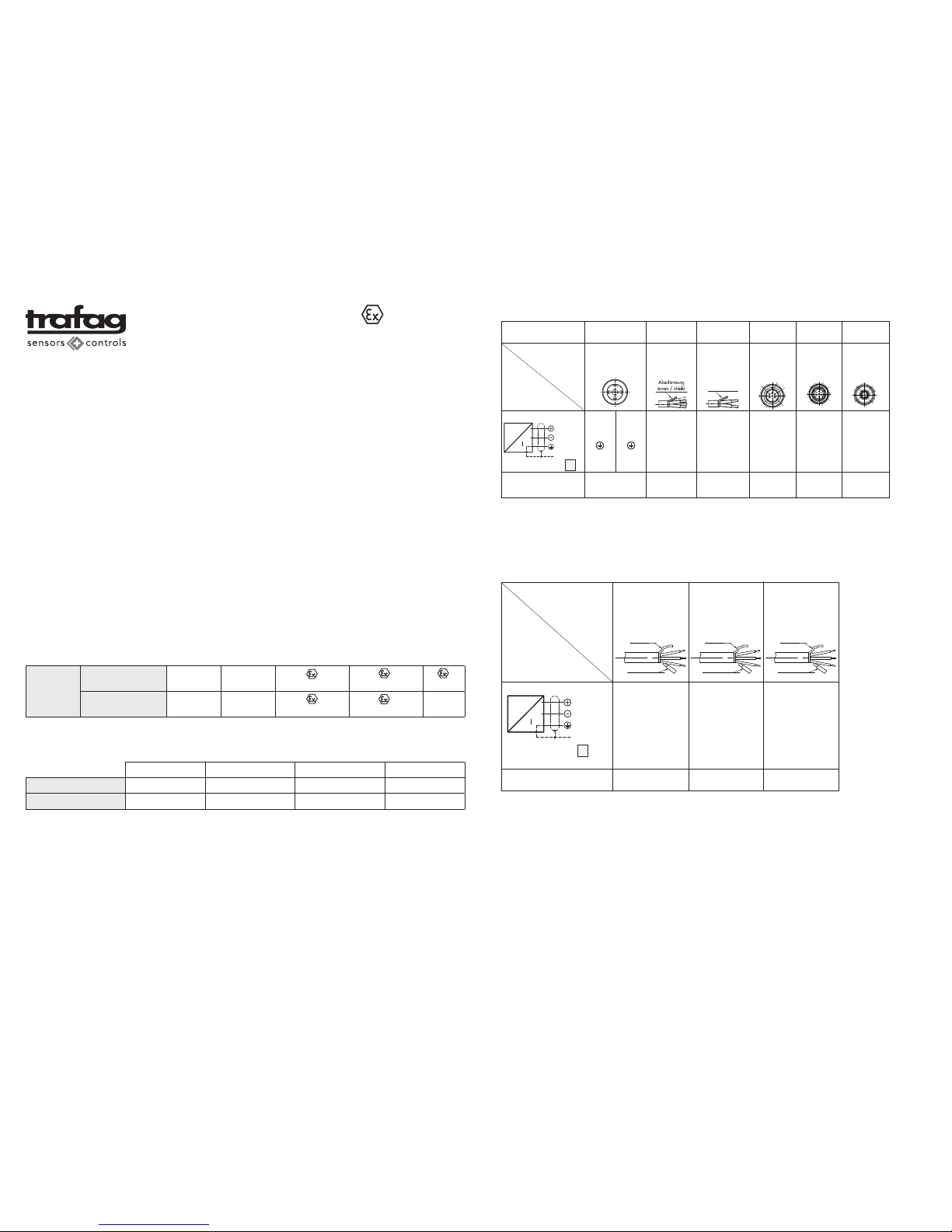
Electrical connection / Elektrischer Anschluss EXNT 8292
* Ventilation via cable end / Entlüftung über das Kabelende
1)
Provided female connector is mounted according to instructions / nur mit vorschriftsmässig montierter Kabeldose gültig
2)
Only cable versions or female plug with shield connection/ nur Kabelvarianten oder Kabeldose mit Schirm-Anschluss
3)
Turning of pin insert max. ± 45° / Verdrehung des Steckereinsatzes max. ± 45°
Protection / Schutzart
8292.XX.XXXX.XX.19
1
2
3
05
Execution
Ausführung
Output
Ausgangssignal
IP65
1) 3)
Us
(pos. Supply)
P
4-20mA
Us
(neg. Supply)
Earth
(housing)
Shield
2)
EN175301-803-A
(DIN43650–A)
3
1
5
14
IP67
Binder
723
2
1
IP65
1)
brown
black
ye/gn
blue = not connected
IP67
1)
IP65
1)
MIL-C
26482
M12x1
5-pol.
A
C
F
4
1
5
02
Cable*
(4 x 0.5mm2)
78
35
1
2
3
4
5
B
C
D
E
F
A
1
4
3
2
5
IP67
Cable*
(2 x 0.75mm
2
)
80
1 (black)
2 (black)
–
Abschirmung
écran / shield
Temperature range
Temperatur-Einsatzbereich
–40 ... +120°C–40 ... +120°C –40 ... +80°C –30 ... +95°C –40 ... +120°C
–40 ... +120°C
Devices for Zones:
Geräte für Zonen:
0, 20 (Ga;Da) and Mining (Ma)
0, 20 (Ga;Da) and Mining (Ma)
SEV 11 ATEX 0201 X IECEx SEV 11.0003 X
II 1G Ex ia IIC T4/T6 Ga II 1D Ex ia IIIC T130° Da I M1 Ex ia I Ma
0/1,20 (Ga/Gb;Da) SEV 11 ATEX 0201 X IECEx SEV 11.0003 X
II 1/2G Ex ia IIC T4/T6 Ga/Gb II 1D Ex ia IIIC T130° Da
Attention!
Additional measure against static charges are required for Zone 0
to 20 for these cables (laid with earthed metal braid, metal hose
or metal pipe).
Any manipulation on the ventilation tube will result in warranty loss.
Jede Manipulation am Entlüftungsschlauch führt zum Garantieverlust.
2)
For all cable versions / für alle Kabelvarianten
Us
(pos. Supply)
P
4-20mA
Us
(neg. Supply)
Earth
(housing)
Shield
2)
8432.XX.XXXX.XX.19
Execution
Ausführung
Output
Ausgangssignal
32
Cable
FEP
ø 6 mm
(5 x 0.22mm2)
Abschirmung
écran/shield
Entlüftung
ventilation/venting
22
Cable
PUR
ø 6 mm
(5 x 0.22mm2)
42
Cable
PE
ø 6 mm
(6 x 0.22mm2)
Temperature range
Temperatur-Einsatzbereich
–20 ... +70°C–20 ... +70°C –20 ... +70°C
Abschirmung
écran/shield
Entlüftung
ventilation/venting
Abschirmung
écran/shield
Entlüftung
ventilation/venting
white
brown
yellow
(green = not connected)
(red = not connected)
Electrical connection / Elektrischer Anschluss EXL 8432
Achtung!
Die Wahl des Kabel- bzw. Steckertyps kann den möglichen T-Einsatzbereich
zusätzlich einschränken. Die maximale Temperatur gemäss Typenschild
darf jedoch in keinem Fall überschritten werden, auch wenn dies das
Kabel zuliesse.
Attention!
Selection of the cable or plug type can also restrict the possible T-application
area. The maximum temperature according to the nameplate may not be
exceeded under any circumstances, even if the cable would permit this.
Achtung!
Für Zone 0 bzw. 20 sind bei diesen Kabeln zusätzliche Massnahmen
gegen statische Aufladung notwendig (Verlegung mit geerdetem
Metallgeflecht, Metallschlauch oder Metallrohr).
Standard
92
1
2
white
brown
yellow
(green = not connected)
(red = not connected)
white
brown
yellow
(green = not connected)
(pink = not connected)
(grey = not connected)
Page: 4 (4)
www.trafag.com Page: 3 (4)
Cable type Material
Ccc
(core-core)
Ccs
(core shield)
Lc
22 PUR 5 x 0.22mm
2
100 pF/m 170 pF/m 0.90 uH/m
32 FEP 5 x 0.22mm
2
60 pF/m 110 pF/m 0.90 uH/m
42 PE 5 x 0.22mm
2
80 pF/m 120 pF/m 0.28 uH/m
78 FDR 4 x 0.5mm
2
122 pF/m 204 pF/m 1.20 uH/m
80 PVC 2 x 0.75mm
2
135 pF/m 185 pF/m 0.65 uH/m
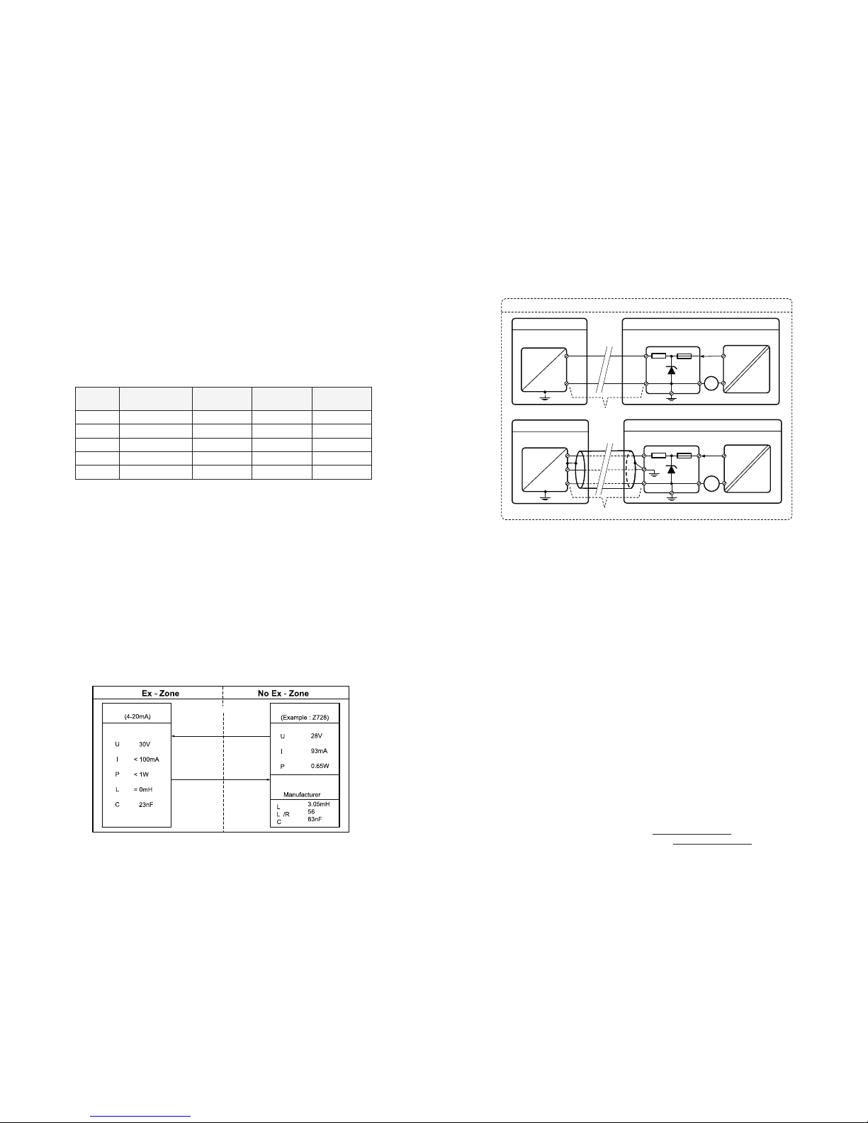
Principle schematic with Zener Barrier Z728
Pressure-Transmitter
Ex ia IIC T4
i
i
i
i
i
≤
≤
Ex Barrier
(Ex ia) IIC
O
O
O
C
Cable
≤ 60nF
L
Cable
≤ 0.5mH
Connection (Cable)
(4...20mA)
O
C C
O
Max. Parameters
L
O ; LC/RC ; CO
Installations examples:
(16.5...28V)
R Fuse
3 x Z
4...20mA
Hazardous Area
Safe Area (Non Ex-Area)
A
Power Supply
P
I
(16.5...28V)
~
=
~
Ex-Barrier Z728
(28V, 93mA, 0.65W)
4...20mA
Hazardous Area Safe Area (Non Ex-Area)
A
Power Supply
Examples with Ex-Barrier Z728
P
I
Transmitter
8292 / 8432
C
Out
= 23nF
L
Out
= 0mH
Ex-Barrier Z728
(28V, 93mA, 0.65W)
Cable : Max. 60nF ; 0.5mH @ Us = 28VDC
Cable : Max. 60nF ; 0.5mH @ Us = 28VDC
R Fuse
3 x Z
=
~
~
C
Out
= 23nF
L
Out
= 0mH
Transmitter
8292
Failure to comply with the electrical connection values or confusing the
contacts is dangerous!
For transmitters with plugs, exclusively use the supplied mating plugs with
a gasket. The IP protection class is only ensured with a properly installed
plug and gasket.
If the transmitter is not connected to the earth via the pressure connector or
the housing, earthing must be ensured via the cable shield or the potential
pressure equalising line in the connector.
Maintenance
Trafag pressure transmitters are maintenance-free.
The provisions of standard EN 60079-17 are to be followed.
You should regularly (e.g. annually) check the condition of the plugs and the
connection cables for damage.
Defective plugs or cables must be replaced immediately.
The required intervals must be determined by the operator depending on
the application conditions.
Only original manufacturer parts may be used for replacement
Cleaning of EXL 8432
For cleaning purposes, the black protection cap can be removed.
The transmitter should be cleaned with a detergent compatible with the
transmitter materials as listed in the datasheet www.trafag.com/H72330.
It is strongly recommended to refrain from any mechanical cleaning of the
ceramic membrane as it is very sensitive and can be easily damaged.
Disposal
For disposal please send the pressure transmitter back to the supplier.
Das Nichteinhalten der angegebenen elektrischen Anschlusswerte oder
die Verwechslung von Kontakten ist gefährlich!
Verwenden Sie bei den Transmittern mit Stecker ausschliesslich den jeweils
mitgelieferten Gegenstecker mit Dichtung. Die IP-Schutzart ist nur bei korrekt
montiertem Stecker und Dichtung gewährleistet.
Ist der Transmitter nicht über den Druckanschluss, oder das Gehäuse
mit Erde verbunden, muss die Erdung über den Kabelschirm oder den
Potentialausgleichsleiter im Kabel erfolgen.
Instandhaltung
Die Trafag Drucktransmitter sind wartungsfrei.
Für die Inspektion und Wartung sind die Bestimmungen der Norm
EN 60079-17 zu beachten.
Der Zustand der Stecker und Anschlusskabel soll regelmässig (z.B. jährlich)
auf Beschädigungen überprüft werden.
Defekte Stecker oder Kabel müssen sofort ersetzt werden.
Die erforderlichen Intervalle müssen in Abhängigkeit von den Einsatzbedinugngen vom Betreiber festgelegt werden.
Für den Austausch dürfen nur Originalersatzteile des Herstellers verwendet
werden.
Reinigung EXL 8432
Zu Reinigungszwecken kann die schwarze Abdeckkappe entfernt werden.
Der Transmitter darf nur mit Mitteln gereinigt werden, die mit den im Datenblatt www.trafag.com/H72330 aufgeführten Materialien kompatibel sind.
Von der mechanischen Reinigung der Keramik-Membrane ist abzusehen, da
sie sehr empfindlich ist und leicht beschädigt werden könnte.
Entsorgung
Für die Entsorgung senden Sie die Drucktransmitter zurück an den Lieferanten.
See data sheet for complete technical specifications:
Vollständige Spezifikationen siehe Datenblatt:
EX Pressure Transmitter 8292 www.trafag.com/H72329
EX Submersible Pressure Transmitter 8432 www.trafag.com/H72330
We reserve the right to make alternations as technical progress may warrant H73329g Trafag AG 08/2017
Electrical characteristic values:
Ui ≤ 30 VDC (10…30VDC)
Ii = <100mA
Pi = <1W
Maximum effective capacity and inductivity of the pressure transmitter:
Ci = 23 nF; Li = 0.01mH
Maximum permissible capacity and inductivity of the intrinsically safe
electrical circuit:
Co = 66 nF; Lo = 0.5 mH @ 30V
The following threshold values result for the cable:
Cc = 43 nF; Lc = 0.5 mH @ 30V
Cc = 60 nF; Lc = 0.5 mH @ 28 V
Installation
The device must be installed by especially qualified persons according to
the requirements of the installation standard EN60079-14 and the relevant
national regulations.
The maximum mounting torque for the pressure transmitter 8292 is 30 Nm.
Certified, accompanying operating resources (safety barrier) are to be included
for the use of the pressure transmitter.
For level measurement applications on ships under certification GL (German
Lloyd), the cable of such transmitters must be installed inside the tank only.
Attention!
The intrinsically safe electrical circuit must be limited to surge category I,
as specified in IEC 60664-1, or the circuit feed is exclusively via a certified,
intrinsically safe power source with a protective level „ia“.
Only models with metallic plugs or cable feeder are permitted for device
group I (mining) and device group I, Zone 0 and/or 20. This also applies
to all IECEx applications.
Elektrische Kenngrössen:
Ui ≤ 30 VDC (10…30VDC)
Ii = <100mA
Pi = <1W
Maximale wirksame Kapazität und Induktivität des Drucktransmitters:
Ci = 23 nF; Li = 0.01mH
Maximal zulässige Kapazität und Induktivität des eigensicheren Stromkreises:
Co = 66 nF; Lo = 0.5 mH @ 30V
Damit ergeben sich für das Kabel folgende Grenzwerte:
Cc = 43 nF; Lc = 0.5 mH @ 30V
Cc = 60 nF; Lc = 0.5 mH @ 28 V
Installation
Das Gerät muss von speziell qualifizierten Personen gemäss den Anforderungen der Installationsnorm EN60079-14, sowie den einschlägigen nationalen
Vorschriften montiert werden.
Das maximale Anziehdrehmoment für den Drucktransmitter 8292 beträgt
30 Nm.
Für den Einsatz des Drucktransmitters ist zwingend ein zertifiziertes zugehöriges Betriebsmittel (Sicherheitsbarriere) vorzusehen.
Bei Anwendungen für Niveaumessung auf Schiffen unter der Zertifizierung
GL (German Lloyd) darf die Verlegung des Anschlusskabels nur innerhalb
des Tankes erfolgen.
Achtung!
Der eigensichere Stromkreis muss auf die Überspannungskategorie I
begrenzt werden, wie in IEC 60664-1 festgelegt bzw. die Speisung der
Stromkreise erfolgt ausschliesslich aus einer bescheinigten eigensicheren
Stromquelle mit einem Schutzniveau „ia“.
Für Gerätegruppe I (Bergbau) und Gerätegruppe I, Zone 0 und/oder 20
sind nur Modelle mit metallischen Steckern oder Kabelabgang zulässig.
Dies gilt auch für alle IECEx-Anwendungen.
 Loading...