

Page 1

ASSEMBLY
GUIDE
Please read this entire manual before installation and use of this pellet fuel-burning
appliance. Failure to follow these instructions could result in property damage, bodily
injury, or even death. Contact your local building or re ocials about restrictions and
installation inspection requirements in your area.
A MAJOR CAUSE OF FIRES IS FAILURE
TO MAINTAIN REQUIRED CLEARANCES
(AIR SPACES) TO COMBUSTIBLE MATERIALS.
IT IS OF UTMOST IMPORTANCE THAT
THIS PRODUCT BE INSTALLED ONLY IN
ACCORDANCE WITH THESE INSTRUCTIONS.
SAVE THESE INSTRUCTIONS.
WARNING!
Many parts of the grill will become very hot during operation. Care must be taken to avoid burns,
both during operation and afterwards, while the grill is still hot.
• Never leave the grill unattended when young children are present.
• Never move the grill when it is operating.
• Let the grill cool thoroughly before moving or attempting to transport.
TFB01WLB
TFB85WLB
TFB01WLB-A/E/G/H/L
TFB85WLB-A/E/GH//L
Page 2
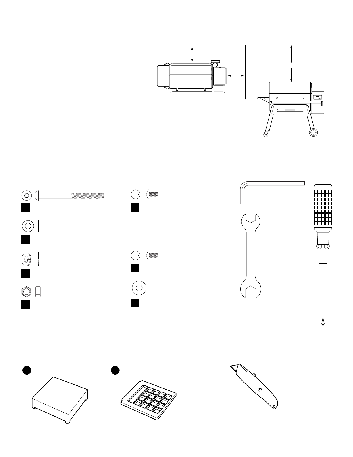
PLACING YOUR GRILL
WARNING!
• When operating this grill under
overhead combustibles, a MINIMUM
of 40 inches (1 m) is required.
• When operating this grill, maintain
a MINIMUM distance of 12 inches
(30.5 cm) from the Grill to
combustibles.
GRILL COMPONENTS
12.00"
(30.5 cm)
12.00"
(30.5 cm)
40.00"
(30.5 cm)
HARDWARE BAG CONTENTS
BAG A (LEGS) BAG B (LEG BRACES)
Bolt: 5/16"-18 socket head (8 pcs)
A
Washer: 5/16" (16 pcs)
B
Spring Washer: 5/16" (8 pcs)
C
Hex Nut: 5/16"-18 (8 pcs)
D
Bolt: 1/4"-20x3/5" (8 pcs)
E
(Actual bolt is black, not silver)
BAG C (SHELVES)
Bolt: 1/4"-20x3/5" (12 pcs)
F
Washer: 1/4" (12 pcs)
G
TOOLS INCLUDED
Hex Key (1 pc)
Wrench (2 pcs)
Screwdriver (1 pc)
GREASE TRAP BAG CONTENTS
(Grease Trap bag located inside hardware bag)
Black Cap for Grease Trap Grease Chute Screen
11 12
2
RECOMMENDED TOOLS
(not included)
Box Cutter or
Scissors
Page 3
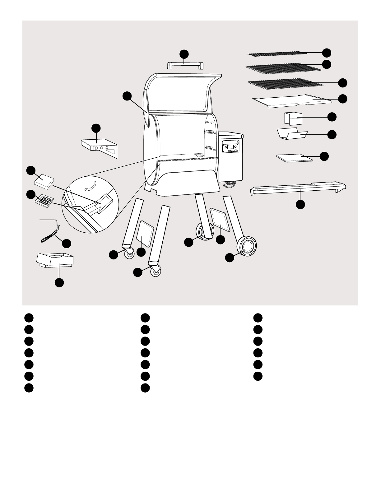
GRILL PARTS DIAGRAM*
11
12
2
1
8
9
9
18
17
16
15
14
13
20
19
10
1
Grill Body & Door
2
Grill Door Handle
3
Front All-Terrain Wheel Leg
4
Rear All-Terrain Wheel Leg
5
Front Locking-Caster Leg
6
Rear Locking-Caster Leg
7
Leg Braces
4
6
7
5
8
Side Shelf
9
Front Shelf
10
Grease Pan
11
Black Cap for Grease Trap
12
Grease Chute Screen
13
Lower Heat Shield
14
Upper Heat Shield
7
3
*Model TFB85WLB shown
15
Grease Drip Tray
16
Bottom Cooking Grate
17
Middle Cooking Grate
18
Top Cooking Grate
19
Meat Probe
20
Cutting Board
GRAB THE 6-PACK, GET THE TOOLS, CUE THE RADIO —
IT’S ALMOST TRAEGER’ING TIME.
traegergrills.com | 3
Page 4

READ ALL INSTRUCTIONS BEFORE INSTALLING AND USING THE GRILL
Traeger’ing is more fun with friends! (No, really, you will need two people to lift the grill.)
REMOVE GRILL PARTS AND
1
PACKAGING
1
NOTE: You should assemble grill on a solid, flat
surface, as you will need to lay it on its back
during assembly.
2
3
5 6
4
4
Page 5

ASSEMBLE EXTERNAL COMPONENTS
2
This will require TWO people.
NOTE: We recommend you use the foam packing to
prop up the grill to make attaching the legs easier.
1
In this step: 1
2
2
NOTE: Do not overtighten legs (leave room for the leg braces).
3
In this step: 3
A
x 2 B x 4 C x 2 D x 2 In this step:
4
4
A
x 2 B x 4 C x 2 D x 2
5
In this step: 5
6
A
x 2 B x 4 C x 2 D x 2 In this step:
6
A
x 2 B x 4 C x 2 D x 2
traegergrills.com | 5
Page 6

NOTE: After leg braces are in place, be sure to
tightly fasten all leg screws.
7
In this step: 7
E
This will require TWO people.
9
8
x 4 In this step:
10
In this step: 8
7
E
x 4
F
x 6 G x 6
6
In this step: 9
F
x 6 G x 6
1211
In this step: 10
Page 7

ASSEMBLE INTERNAL COMPONENTS
3
1
In this step: 11 12 In this step:
2
13
NOTE: Ensure that the drip tray sits between the
two lips of the rear exhaust ports.
3
In this step:
14
4
In this step:
15
5 6
In this step: 16
17 18
In this step:
NOTE: Remember to remove protective plastic film
from control panel before use.
19
20
traegergrills.com | 7
Page 8

Traeger Pellet Grills LLC
1215 E. Wilmington Ave
Salt Lake City, UT 84106
traegergrills.com
09/2016
 Loading...