

Page 1
Söllnerstr. 9 92637 Weiden info@traeger.de +49 (0)961 48 23 0 0
S7-USB user manual
Art.Nr. 9352-S7-USB
documentation of version XXX
1 Description
The MPI-USB cable connects the computer via USB with a MPI interface (9 pin interface of the PLC).
2 System requirements
2.1 Operating system (s)
Windows 98 + SE Windows ME/NT/2000 Windows XP Windows Vista Windows 7
2.2 Software
PLC - programming software (eg PG2000, Step © 7, S7 for Windows, Microwin) Direct driver for SimaticManager for USB PLC - VCOM Software A video description of the installation of direct-driver and how to
configure it can be found on the page support!
2.3 Hardware
USB 1.1 - Type A
2.4 Provided PLCs
S7-200 S7-300 (provides baudrates up to 12M (when the PLC is able to support this) S7-400 (provides
baudrates up to 12M) FM-devices Sinamix (Step7-direct-driver up V1.20 or PLCVCom up V2.71)
MicroMaster and other electrical drives and inverter-feds (Step7-direct-driver up V1.20 or PLCVCom up
S7-USB user manual 1 / 85 2019/10/05 05:07
Page 2
Söllnerstr. 9 92637 Weiden info@traeger.de +49 (0)961 48 23 0 0
V2.71) Sinumerik (only PLC-side) SEW-EURODRIVE power inverter and at last routing of S7-PLCs
3 Connecting options
S7-USB directly connected to the PC.
S7-USB is connected to the PC via a USB hub.
S7-USB Connection options with control terminal
4 Installation
4.1 Hardware
The S7/MPI-USB is plugged directly into the PLC. Via the USB cable of the module can be connected to the
PLC as follows:
Normal installation (for programming)
The MPI cable will be connected to the S7 PLC via the 9 pin connector (short side of the cable). The USB
connector on the long side of the cable will be connected with the computer.
S7/MPI-USB as HMI (Human Machine Interface) – adapter
The HMI – function provides the possibility to connect a operator panel (which has instead of a MPI
interface a USB device and understands the HMI protocol) with a S7 PLC (300/400). Connect the cable
between the terminal and the PLC. The HMI – protocol must be part of the operator panel.
There must be a serial communication with the operator panel if this op is new/used at the first time.
Therefore connect your operator panel with the serial COM interface of your computer. After the
communication has been running successfully the panel is ready to be connected to the PLC.
4.2 Software
To communicate with the PLC, please install following products for MPI-USB, S7-USB, MPI-II[only USB], MPILAN and S7-LAN:
Product Driver
TIA-Portal
Simatic-Manager TIC ⇒ “TIC ETH/USB” for MPI, PPI or PROFIBUS
Starter-Software TIC ⇒ “TIC ETH/USB” for MPI or PROFIBUS
MicroWin TIC ⇒ “TIC ETH/USB” for PPI and S7-22x-PLC
MicroWin PLCVCom for S7-21x-PLC (no MultiMaster-protocol)
PG-2000 PLCVCom or for S7-LAN/MPI-LAN direct in interface-settings
S7 for Windows TIC ⇒ “TIC ETH/USB” for MPI or PROFIBUS over PD/PC-interface
S7 for Windows PLCVCom
To communicate with the PLC, please install following products for MPI/PPI and MPI-II[only serial]:
TIC ⇒ “TIC ETH/USB” for MPI, PPI or PROFIBUS
configuration of driver with control-panel ⇒ setting PD/PC-interface
Product Driver
TIA-Portal no support because Siemens has taken out the serial support in the driver “PC-Adapter”
S7-USB user manual 2 / 85 2019/10/05 05:07
Page 3
Söllnerstr. 9 92637 Weiden info@traeger.de +49 (0)961 48 23 0 0
Product Driver
Simatic-Manager included driver “PC-Adapter” for MPI and PROFIBUS
Starter-Software included driver “PC-Adapter” for MPI and PROFIBUS
MicroWin included driver “PC/PPI-cable”
PG-2000 Standard-function, configuration in the interface-settings
S7 for Windows Standard-function, configuration in the interface-settings
4.3 USB-driver-installation for 32-bit-systems
The S7-Interface S7-USB, MPI-USB or MPI-II-Cabel over USB as well as the devices of TeleService-family will
be connected to USB 1.1-compatible port of the PC.
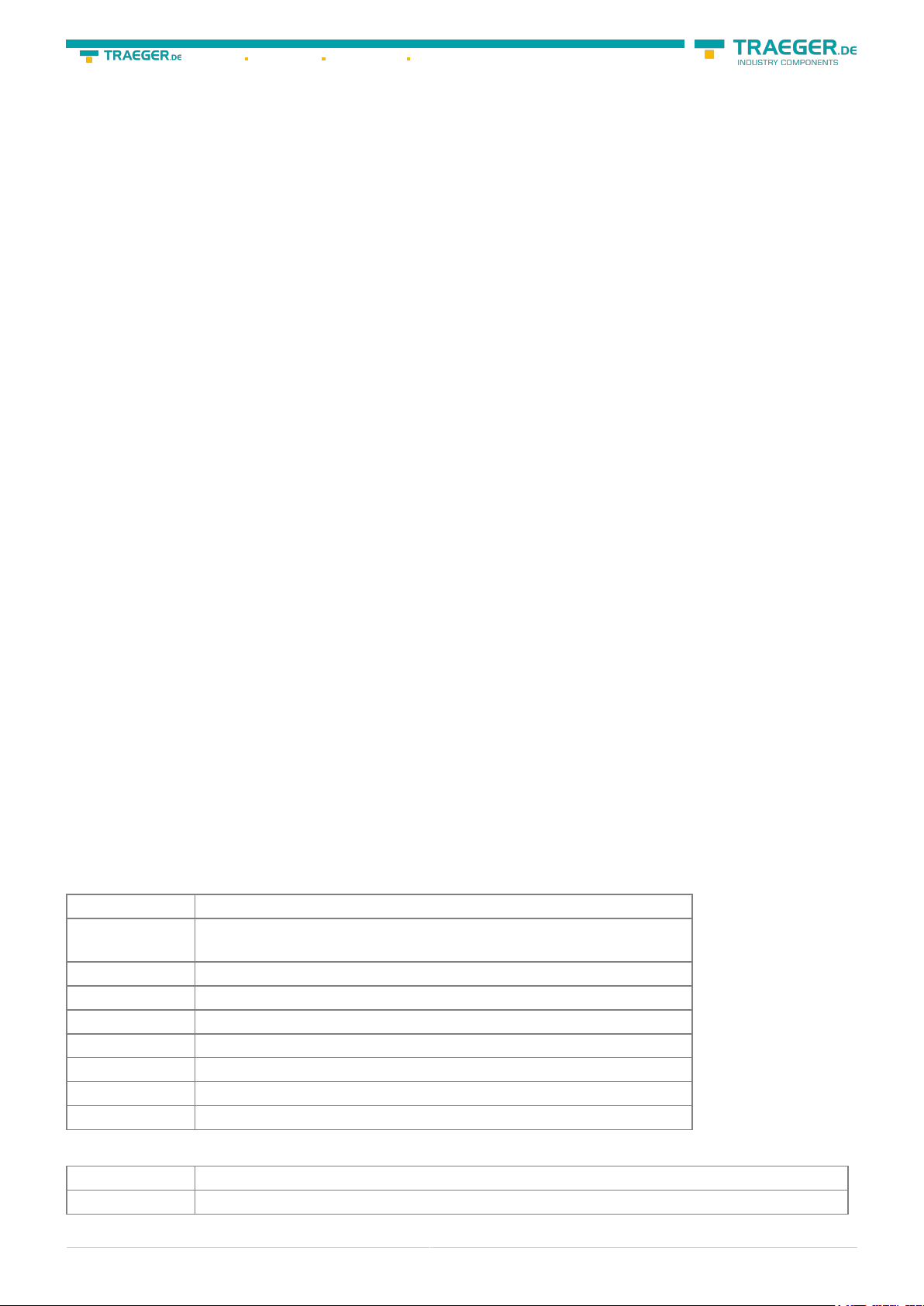
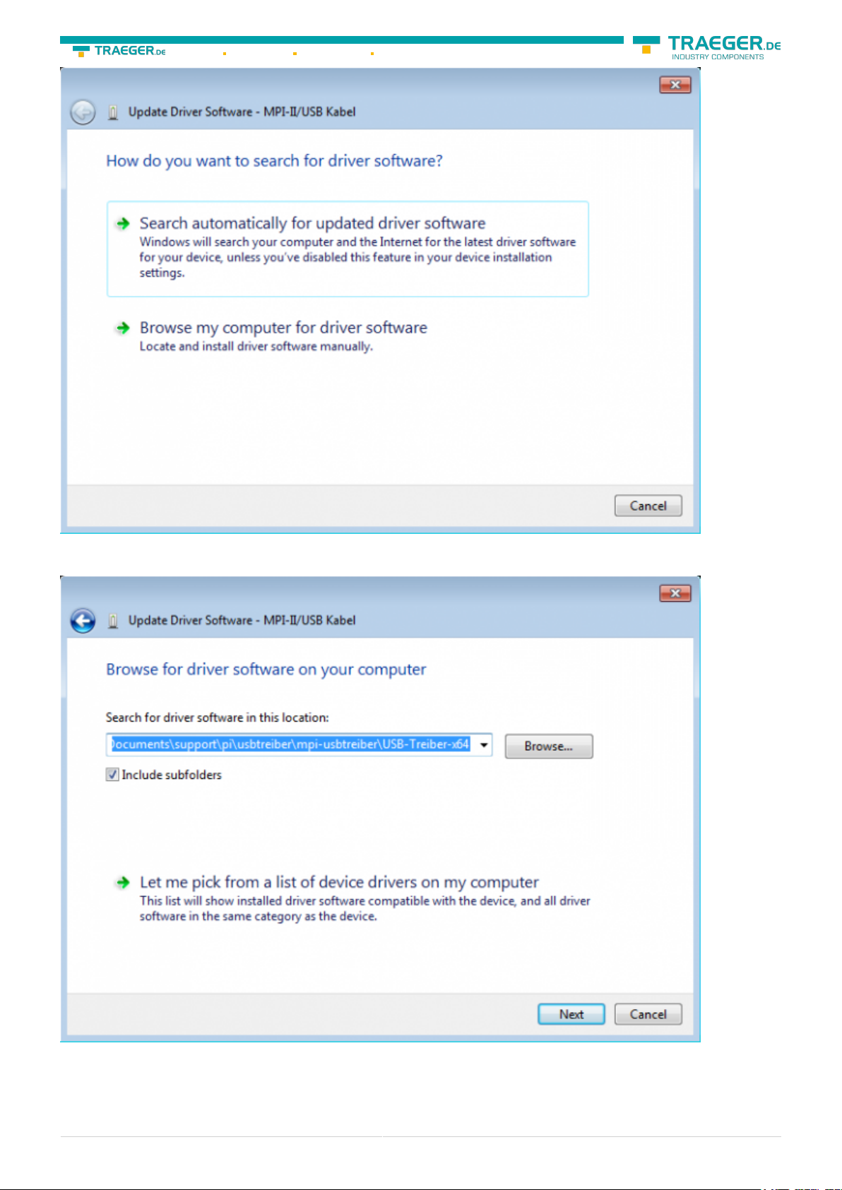
This opens the Hardware-Installation-Wizard:
We don´t need a connection to Windows update.
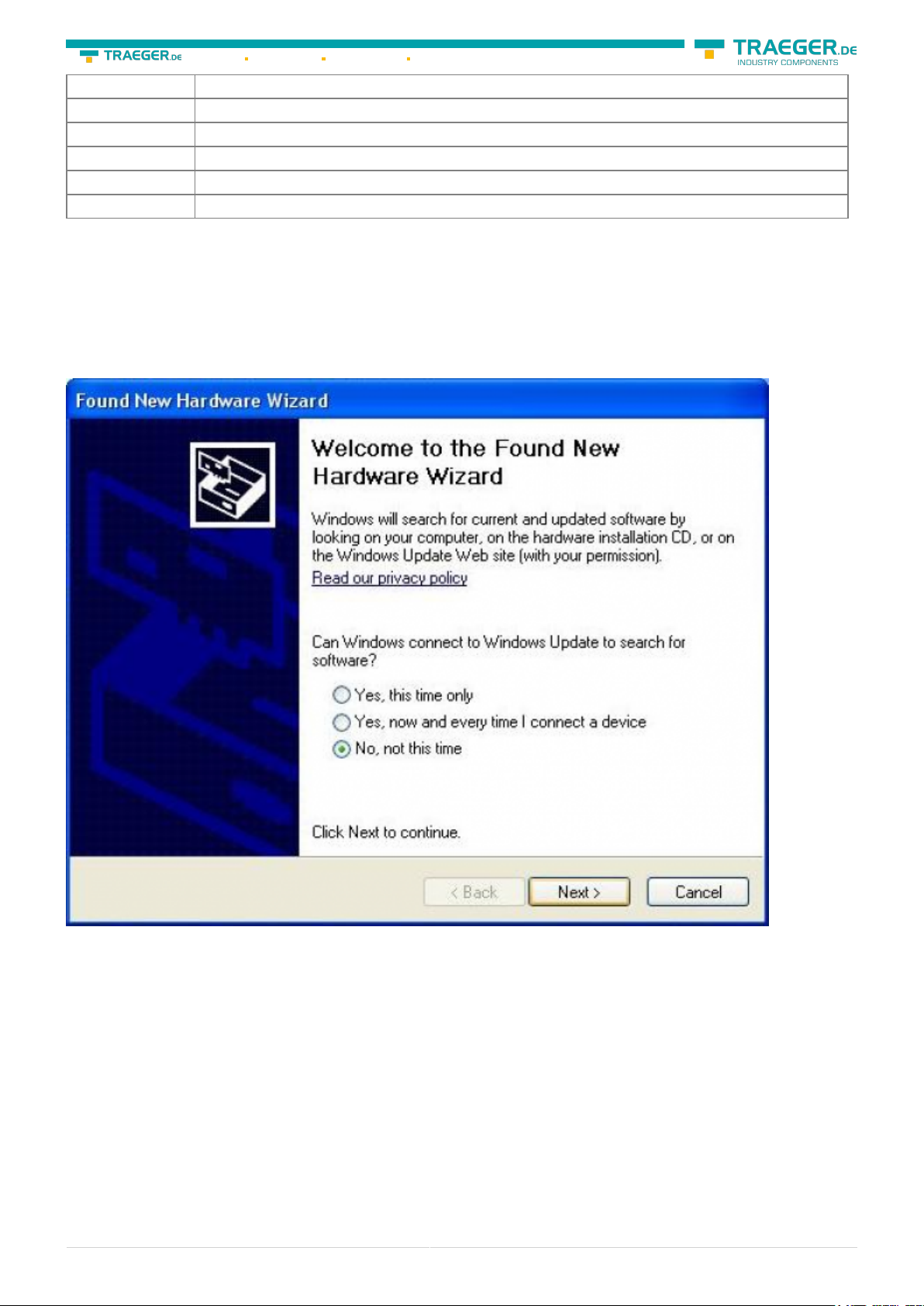
Select now “Install from a list or specific location”:
S7-USB user manual 3 / 85 2019/10/05 05:07
Page 4
Söllnerstr. 9 92637 Weiden info@traeger.de +49 (0)961 48 23 0 0
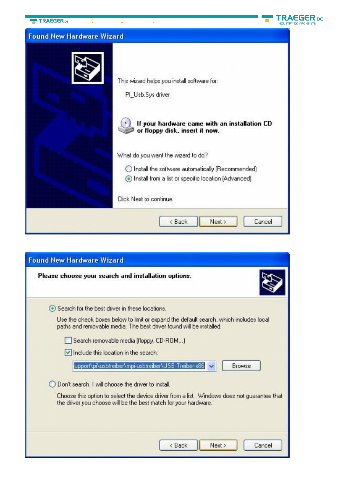
Enter as source the folder “..\USB-Treiber-x86”. Either in the folder where the downloaded drivers were
extracted or the directory on the product CD:
S7-USB user manual 4 / 85 2019/10/05 05:07
Page 5
Söllnerstr. 9 92637 Weiden info@traeger.de +49 (0)961 48 23 0 0
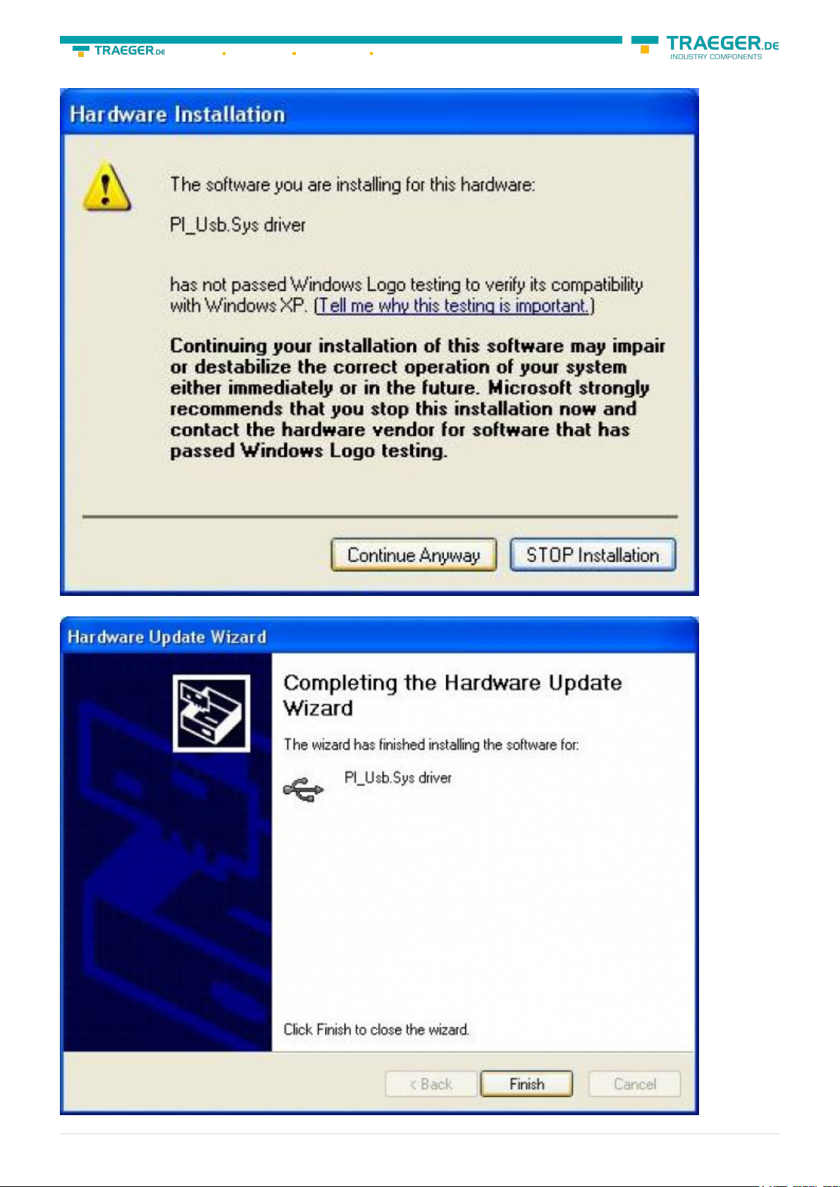
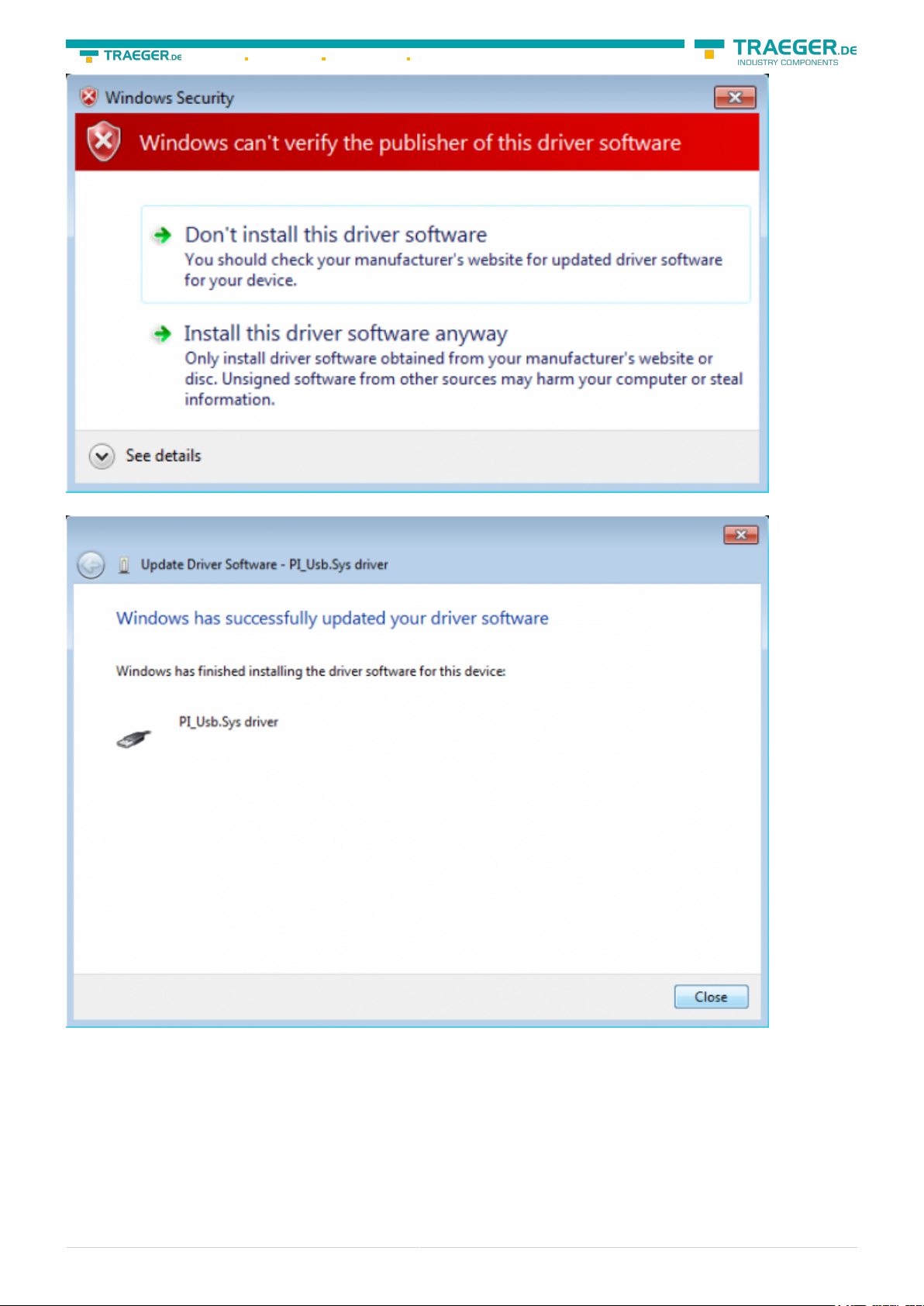
The message of windows logo test skip with “Continue Anyway”:
After copying the data appears a little moment later the success message:
S7-USB user manual 5 / 85 2019/10/05 05:07
Page 6
Söllnerstr. 9 92637 Weiden info@traeger.de +49 (0)961 48 23 0 0
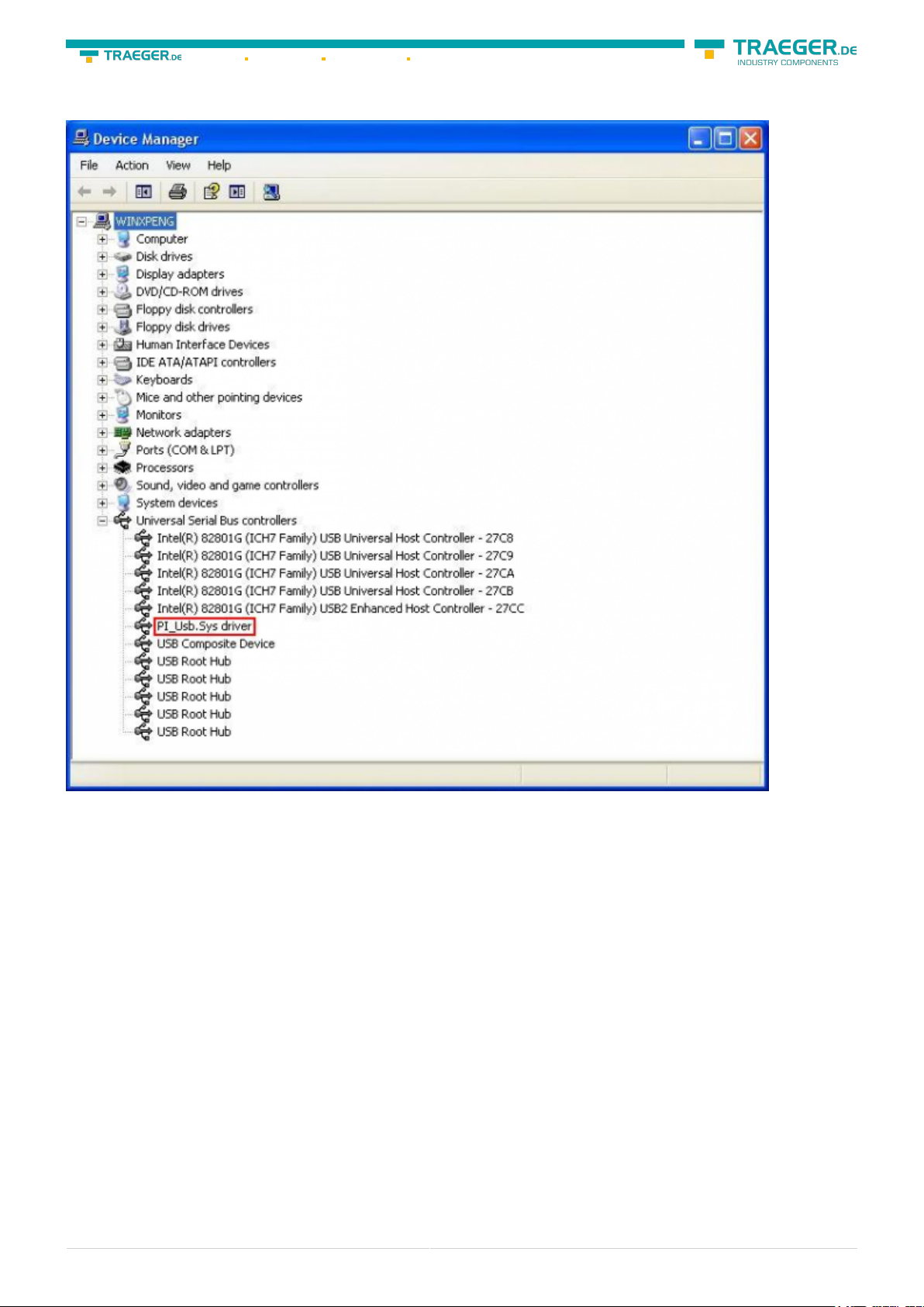
Upon a successful installation the “PI_Usb.Sys driver” will be displayed without any warnings in the device
manager:
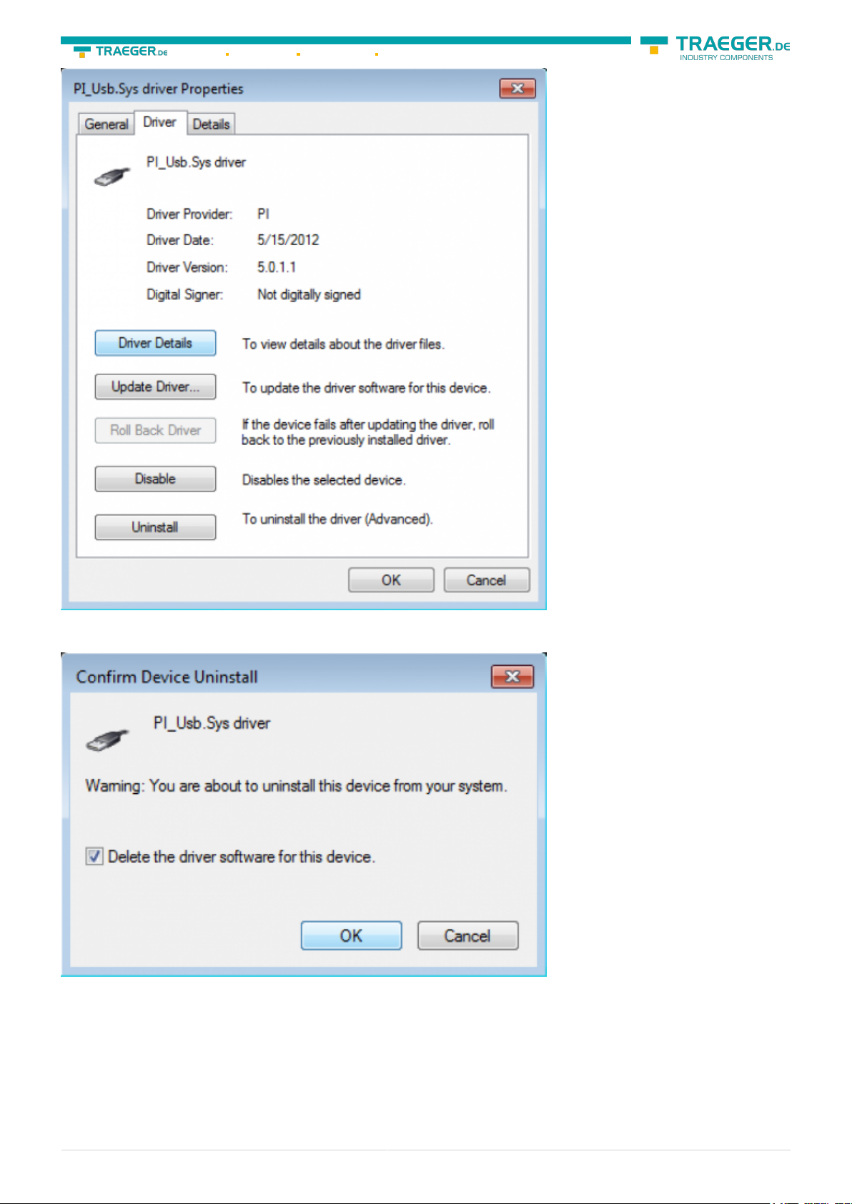
Will this entry in the device manager shown with a “yellow exclamation mark”, then please install the
driver again or look in the driver properties about the reason.
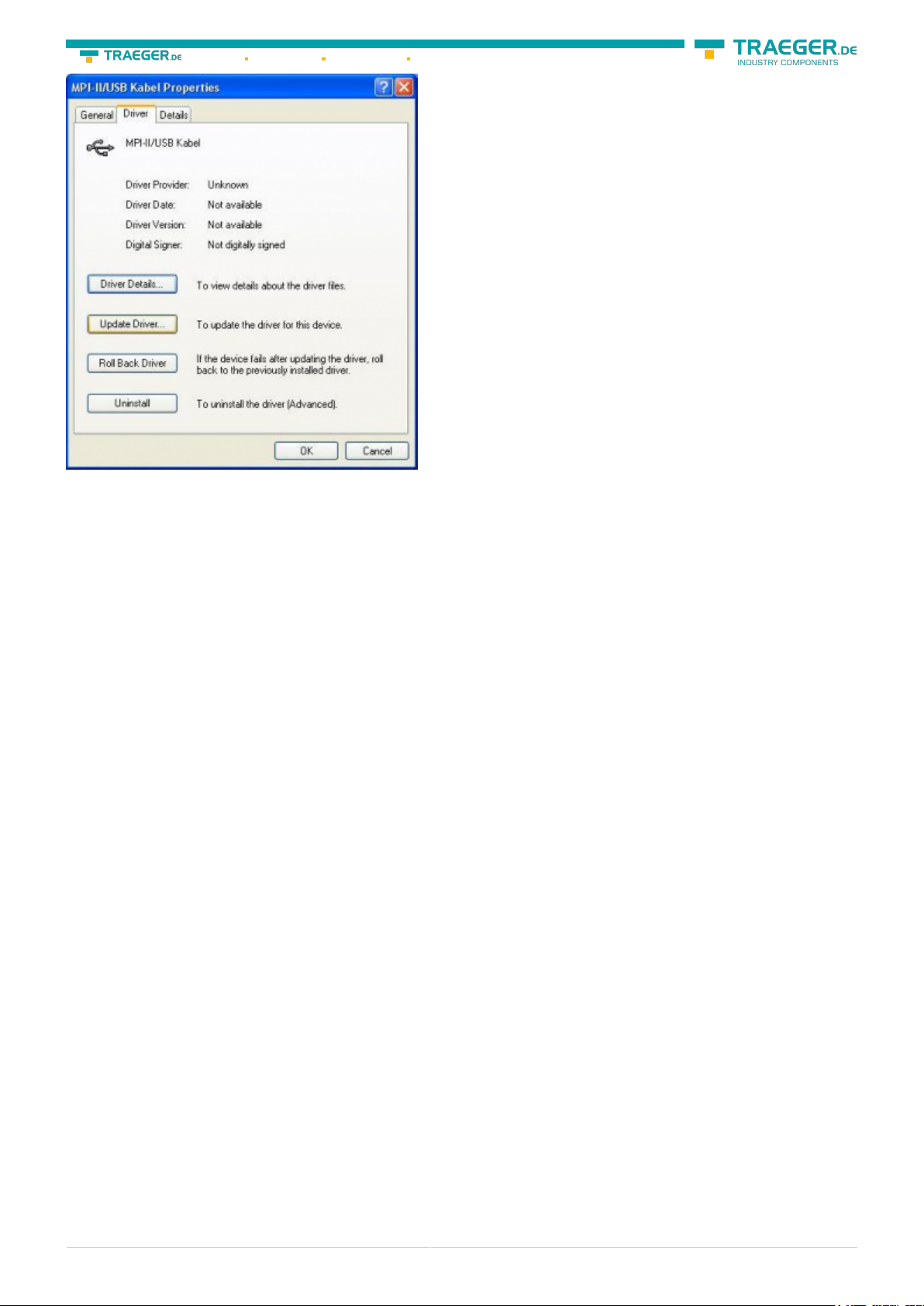
If the driver has to be updated, please use the function “Update …” in the driver properties:
S7-USB user manual 6 / 85 2019/10/05 05:07
Page 7
Söllnerstr. 9 92637 Weiden info@traeger.de +49 (0)961 48 23 0 0
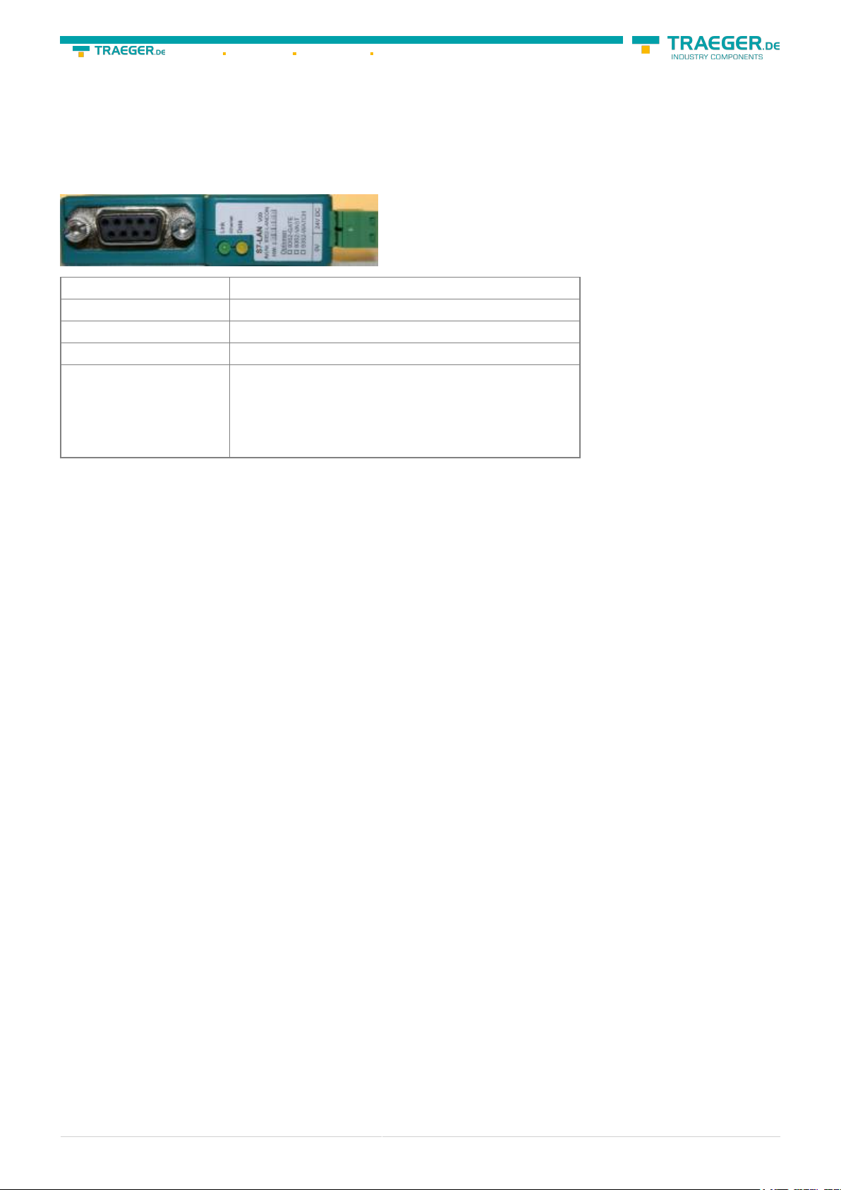
If the driver has to be deleted, please use the function “Uninstall” in the driver properties:
If you install older versions of PLCVCom, Step7-direct-driver or S7IFC, the actual usb-driver will be possible
overwritten by previous versions because it was included until 01/11/2012 in their install-shields!
4.4 USB-driver-installation for Win7 64-bit
The S7-Interface S7-USB, MPI-USB or MPI-II-Cabel over USB as well as the devices of TeleService-family will
be connected to USB 1.1-compatible port of the PC.
After the first plug of the device Win7 displays the message „Installing device driver software“ and after
some time „Device driver software was not installed“. This messages could be closed.
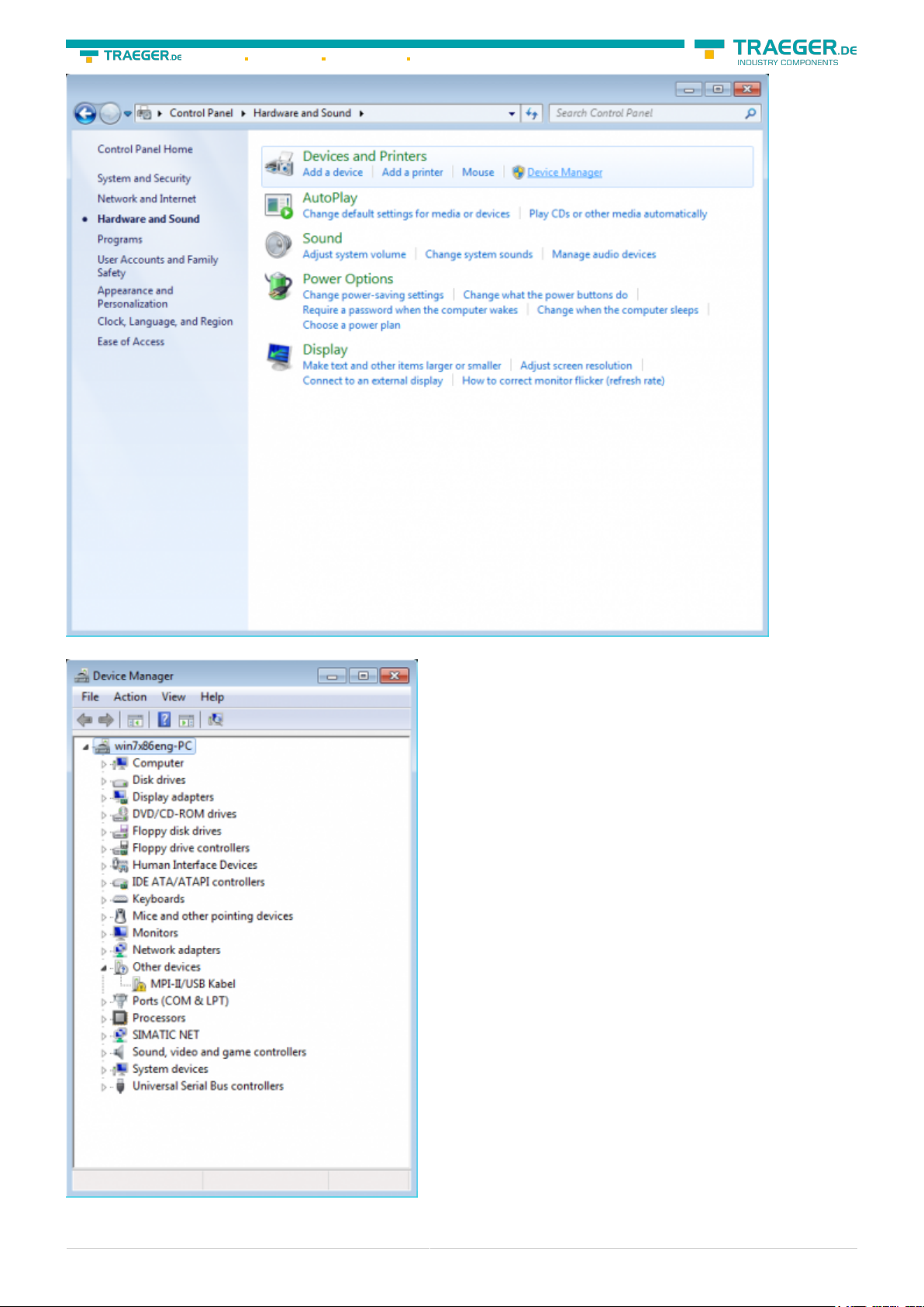
Please start the windows device manager in the control panel.
S7-USB user manual 7 / 85 2019/10/05 05:07
Page 8
Söllnerstr. 9 92637 Weiden info@traeger.de +49 (0)961 48 23 0 0
In the device manager would be the new device shown with a exclamation mark:
With a right mouse-button-click you will open the properties of the new device:
S7-USB user manual 8 / 85 2019/10/05 05:07
Page 9

Söllnerstr. 9 92637 Weiden info@traeger.de +49 (0)961 48 23 0 0
Now select “Update Driver…”:
S7-USB user manual 9 / 85 2019/10/05 05:07
Page 10
Söllnerstr. 9 92637 Weiden info@traeger.de +49 (0)961 48 23 0 0
Please select “Browse my computer for driver software” and define as source the folder “..\USB-Treiberx64”. Either in the folder where the downloaded drivers were extracted or the directory on the product CD:
After pressing “Next” the message appears of windows UAC
S7-USB user manual 10 / 85 2019/10/05 05:07
Page 11
Söllnerstr. 9 92637 Weiden info@traeger.de +49 (0)961 48 23 0 0
Please press install and a little moment later appears the success message
To verify the successful installation, you can look again in the device manager:
S7-USB user manual 11 / 85 2019/10/05 05:07
Page 12

Söllnerstr. 9 92637 Weiden info@traeger.de +49 (0)961 48 23 0 0
Here may appear no exclamation mark!
If the driver has to be updated, please use the function “Update driver …” in the driver properties:
S7-USB user manual 12 / 85 2019/10/05 05:07
Page 13
Söllnerstr. 9 92637 Weiden info@traeger.de +49 (0)961 48 23 0 0
If the driver has to be deleted, please use the function “Uninstall” and set the check-box in “Delete the
driver software for this device”:
If you install older versions of PLCVCom, Step7-direct-driver or S7IFC, the actual usb-driver will be possible
overwritten by previous versions because it was included until 01/11/2012 in their install-shields!
S7-USB user manual 13 / 85 2019/10/05 05:07
Page 14
Söllnerstr. 9 92637 Weiden info@traeger.de +49 (0)961 48 23 0 0
5 Control elements
5.1 Lateral LEDs
Green LED OFF Power OFF (S7-USB is not supplied with voltage)
Green LED is blinking BUS Communication
Green LED is on Power ON (S7-USB is supplied with voltage)
Yellow LED is OFF no error in the communication
1x Module does not come into bus
2x Participants provided with the same MPI address
Yellow LED is blinking
3x Wrong MPI baud rate is used
4x Detected parity error on the bus
5x Buffer overflow condition in module
6 Implementing
Connect your module as described in the chapter “ Hardware installation ” to the PLC and to the
programming device or to your computer.
If you want to respond to a PLC via the module you have to comply the requirements as described in the
chapter “system requirements” . In addition,please make sure that the module is properly connected
6.1 Using the PLC-VCOM
(The PLC-VCOM is only needed if your module is not connected via the 9 pin COM port to the computer. For
products with USB, Ethernet connection, etc., the PLC-VCOM is required)
1. Start the PLC - VCOM application (If it has not already started yet).
2. Click in the main window of the PLC-VCOM, in the status area “configure”. The configuration wizard will
start.
3. It lists all the found modules / cables and the additional information’s such as IP address and MAC
address of the module.
4. Choose the desired MPI cable and click „OK“ to go on.
5. If the connection is established the chosen cable is shown in the section state and on the left side you
can see the status connected.
6. It also displays, the PLC-VCOM the IP address for the module and the IP address of the computer which
is connected to the module.
If you have any problems with the use of PLC-VCOM software, go to the chapter PLC – VCOM and look there
for operating instructions.
S7-USB user manual 14 / 85 2019/10/05 05:07
Page 15
Söllnerstr. 9 92637 Weiden info@traeger.de +49 (0)961 48 23 0 0
6.2 Programming software to use with direct access
After you have adjusted and connected the PLC-VCOM or the programming adapter to the COM-port on
your computer, you will be able to connect with your programming software
to the PLC and work with it.
How you have to adjust your programming software is described in the following points:
6.2.1 PG2000 für S7 (V5.10)
1. Start the PG 2000 software by using the desktop link or by using the application entry in the start menu.
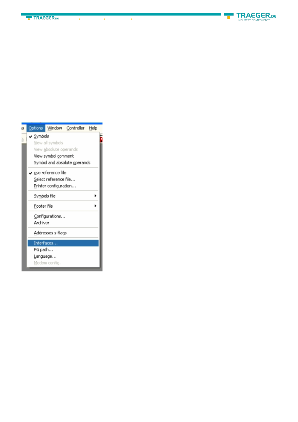
2. Choose from “View” ⇒ “S7-300/400” In the menu “Options“ click “Interfaces“..
S7-USB user manual 15 / 85 2019/10/05 05:07
Page 16
Söllnerstr. 9 92637 Weiden info@traeger.de +49 (0)961 48 23 0 0
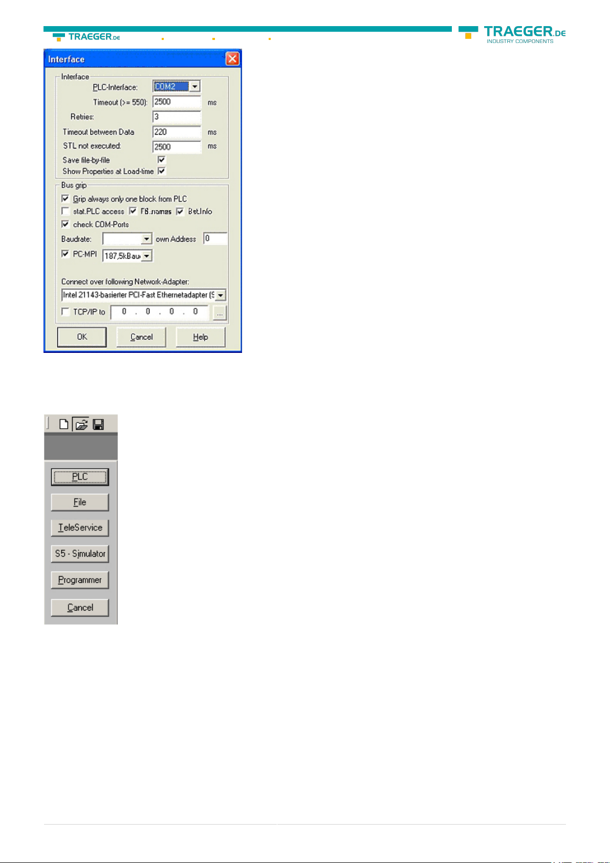
3. A dialog appears, in which you are able to set the “AG-Interface” (COM-port) in the section “Interfaces”.
4. Configure the baud rate in the section “Bus access“ to “19,2k“. Below change the value for PC - MPI to
“187,5kBaud“.
5. Save your configuration by pressing “OK“.
6. Now the software is ready to establish a connection to the PLC Click the symbol “Open“ and afterwards
press “PLC”. Alternative you can click:
„File“ ⇒ „Open“ ⇒ „PLC“
S7-USB user manual 16 / 85 2019/10/05 05:07
Page 17
Söllnerstr. 9 92637 Weiden info@traeger.de +49 (0)961 48 23 0 0
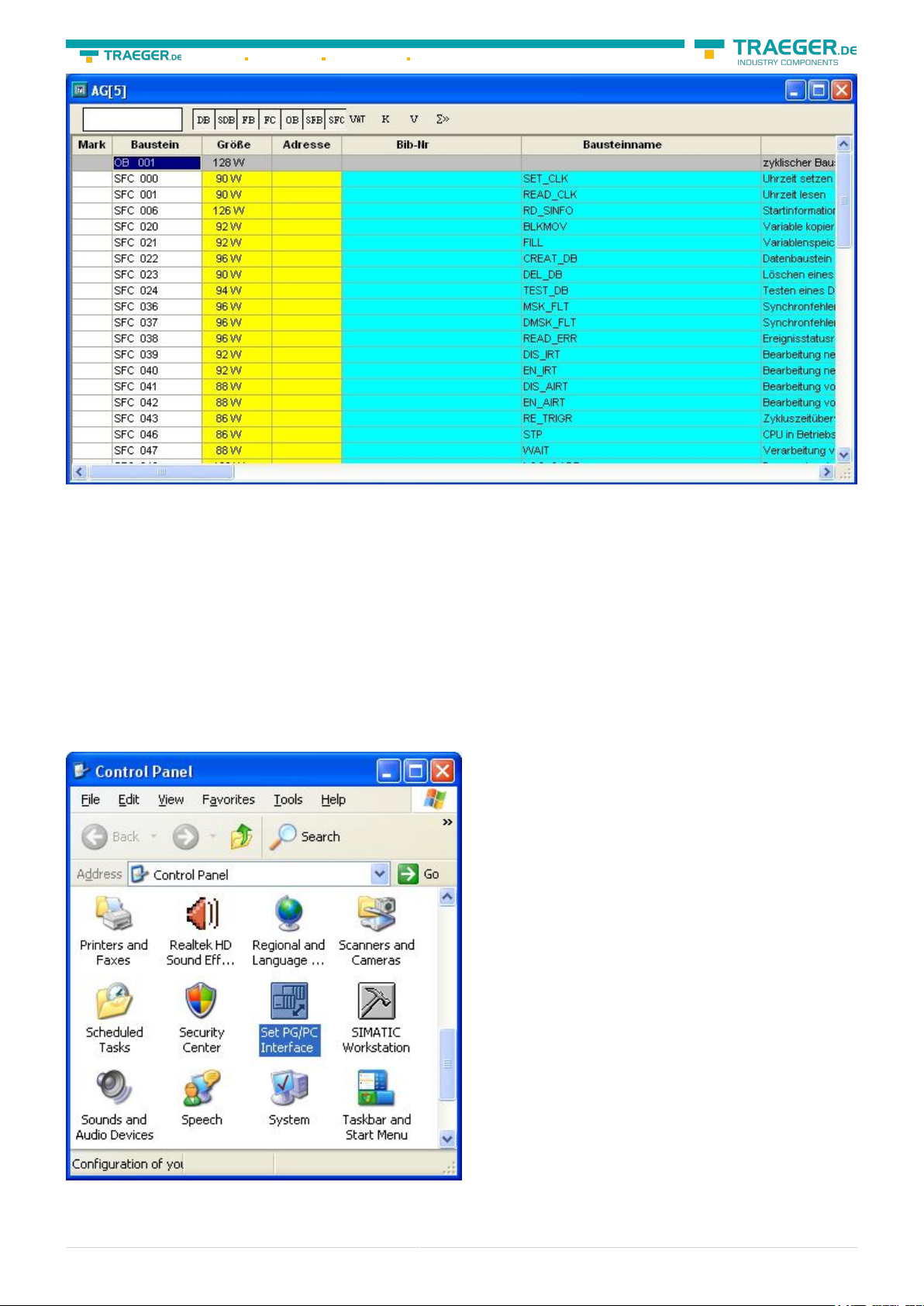
The connection between PG 2000 and the PLC is now established. A new window appears. Now you can
edit the blocks in the PLC.
6.2.2 PSet PG/PC interface
This step is required for the following software:
⇒ SIMATIC Step© 7 Manager (v5.2 + SP1)
⇒ Windows Control Center (WinCC) (v6.0)
⇒ Windows Control Center flexible 2004 (WinCC flexible) (v5.2.0.0)
⇒ ProTool/Pro (v6.0 + SP2)
⇒ Microwin 3.2
1. Open the system configuration by using the start menu. 2. Click on „Set PG/PC interface“.
S7-USB user manual 17 / 85 2019/10/05 05:07
Page 18
Söllnerstr. 9 92637 Weiden info@traeger.de +49 (0)961 48 23 0 0
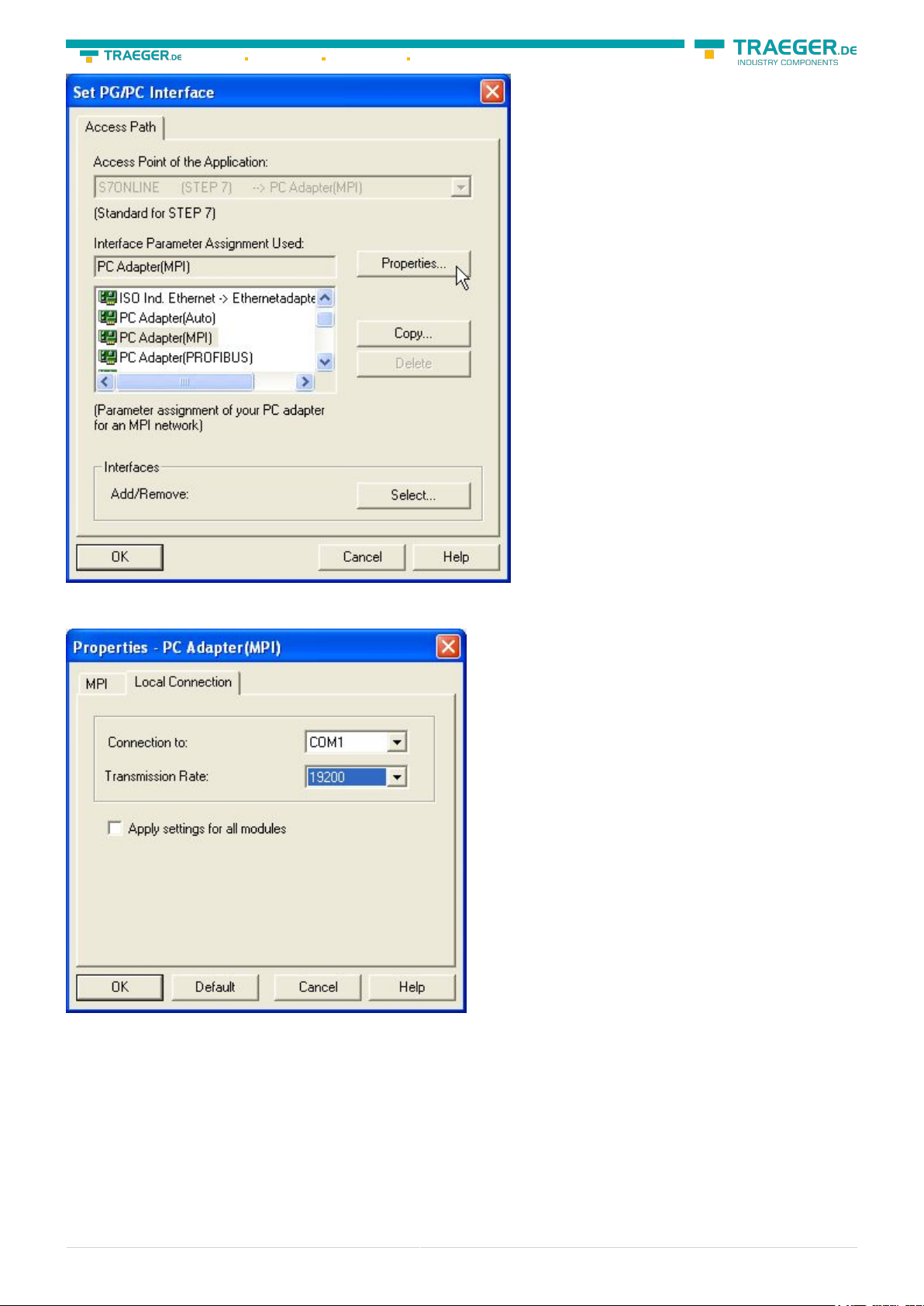
3. A Dialog with a list box named “Interface Parameter Assignment Used:” appears. This box should offer
some “PC - Adapter” entries If this is the case, please continue with the step MPI settings or Profibus
settings. If you can't find these entries go ahead with step PC-Adapter orTCP/IP installation.
6.2.2.1 PC-Adapter(Auto, MPI, PROFIBUS)
4. Click on „Choose“ to add these entries to the PG/PC interface configuration
\
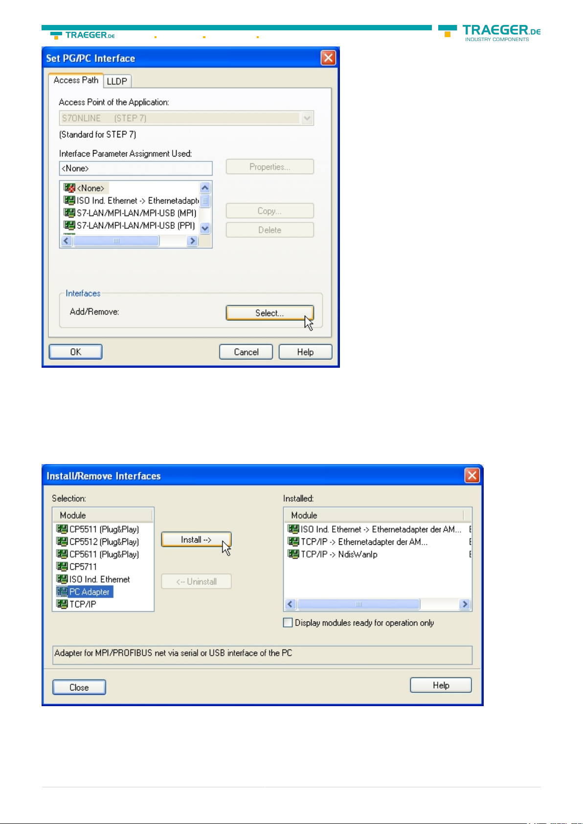
5. In this dialog you can deinstall every installed construction set Furthermore you can add various
modules (see “Selection”) Choose „PC - Adapter“ from the „Selection“ box on the left side and click on
„Install“.
6. The chosen construction set will be installed and a question appears which asks you to use the “MPI“
S7-USB user manual 18 / 85 2019/10/05 05:07
Page 19

Söllnerstr. 9 92637 Weiden info@traeger.de +49 (0)961 48 23 0 0
access for the PLC used. Click “Yes“ if you want to use the „MPI“communication type. Otherwise click
“No“(e.g. if you want to use the “PROFIBUS“ communication type).
6.2.2.2 TCP/IP RFC1006 Communication
7. Press “Select” to add the RFC1006 required elements to the PG / PC - interface configuration.
8. In the dialog “Select”, choose“ TCP / IP” and click on “Install”.
9. After successful installation, click “Close”.
10. Back to the “Set PG/PC interface“ dialog you will now find the desired entries called “PC Adapter(Auto)“ (not supported), “PC - Adapter(MPI)“ and “PC - Adapter(PROFIBUS)“. Now you are able to
configure the bus. If you want to use the “MPI“communication type go ahead with step MPI setting . The
settings for “PROFIBUS” is explained in Profibus setting .
6.2.2.3 MPI setting
S7-USB user manual 19 / 85 2019/10/05 05:07
Page 20
Söllnerstr. 9 92637 Weiden info@traeger.de +49 (0)961 48 23 0 0
11. Select “PC Adapter (MPI)” and click “Properties”.
12. Open the properties dialog Choose the register “Local Connection”
13. Set here the COM port.
14. You also change the “transfer rate” to “19200”.
S7-USB user manual 20 / 85 2019/10/05 05:07
Page 21
Söllnerstr. 9 92637 Weiden info@traeger.de +49 (0)961 48 23 0 0
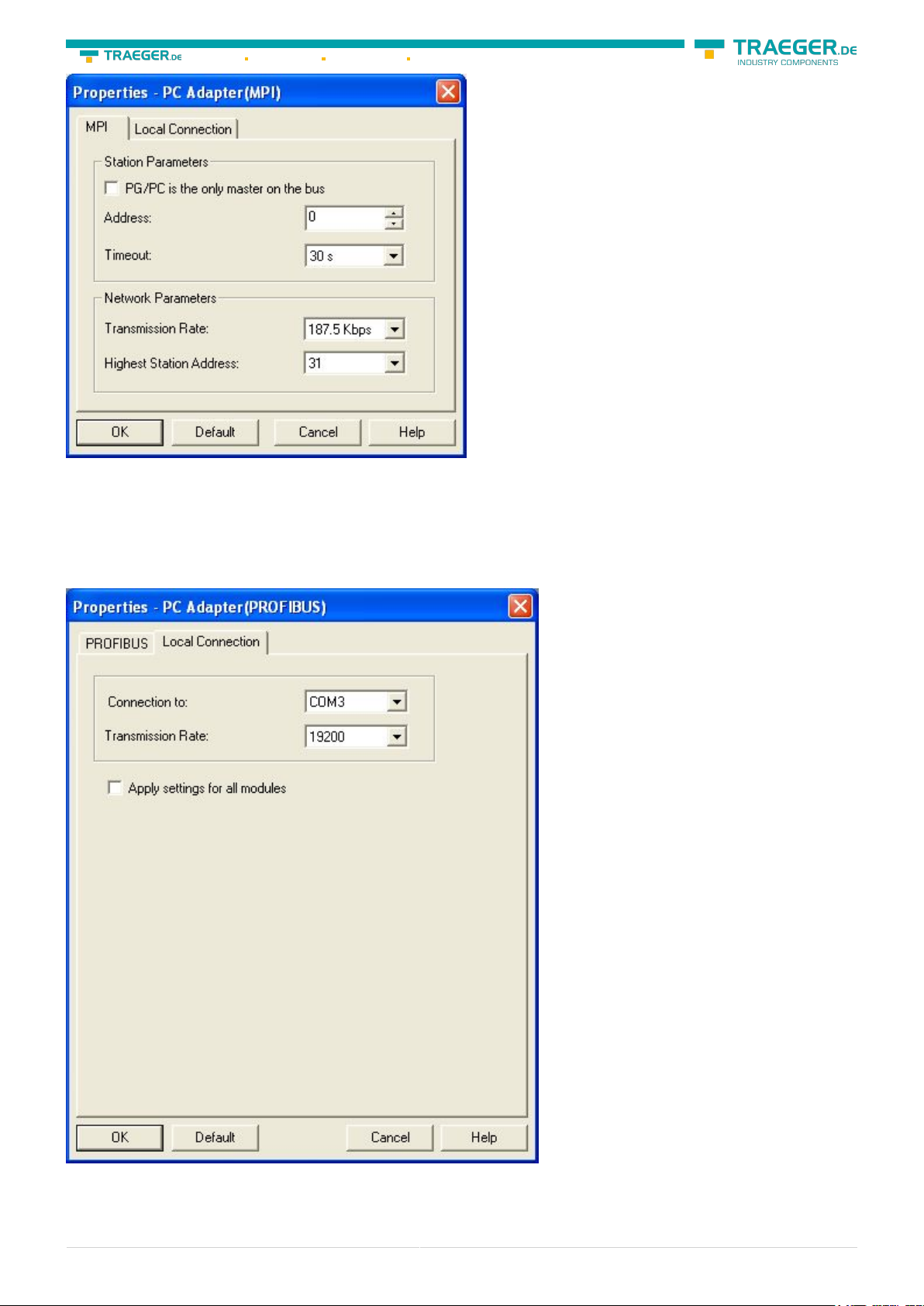
15. In the register card “MPI“choose the “Transmission Rate” to “187,5 kbit/s“. Change the “Highest
Station Address” (HSA) to “126”.
16. Accept your settings with “OK” and exit the “PG / PC interface setting” dialog with “OK”.
6.2.2.4 Profibus setting
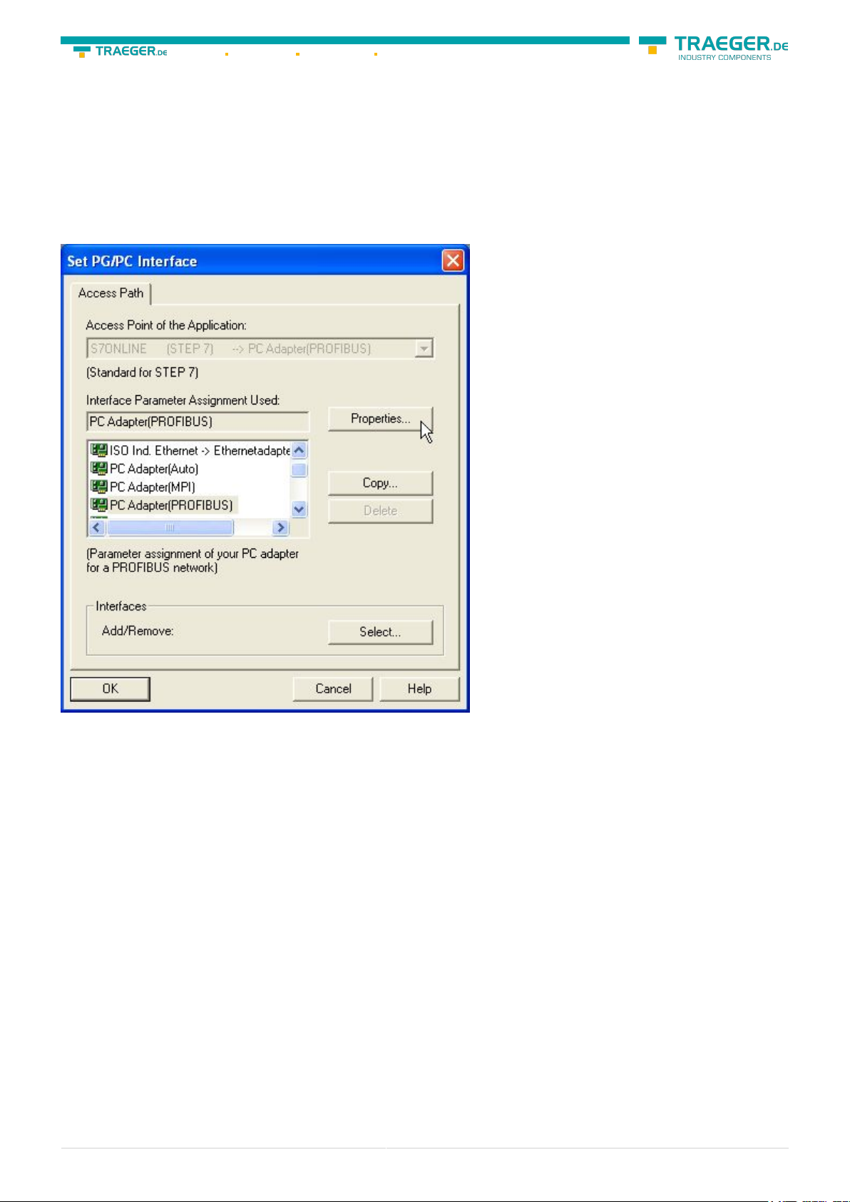
17. Mark the entry „PC - Adapter(PROFIBUS)“ and click on „Properties“.
S7-USB user manual 21 / 85 2019/10/05 05:07
Page 22
Söllnerstr. 9 92637 Weiden info@traeger.de +49 (0)961 48 23 0 0
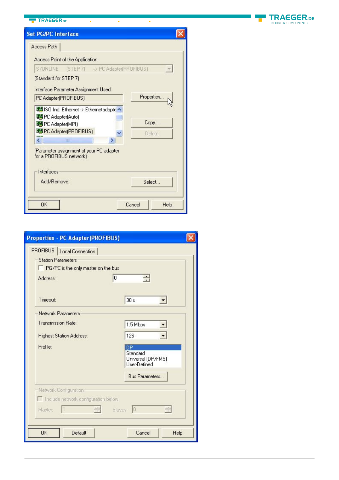
18. In the registry card “Locale connection” you have to set the COM Port. 19. Set the “Transmission Rate”
to “19200”
20. Choose the registry card “PROFIBUS” and set the “Transmission Rate” to “187,5kbit/s”.
S7-USB user manual 22 / 85 2019/10/05 05:07
Page 23
Söllnerstr. 9 92637 Weiden info@traeger.de +49 (0)961 48 23 0 0
21. Set the “Profile“ to “DP“ (“decentralized Peripherals “).
22. Save your settings by clicking the “OK“button and close the opened “Set PG/PC - interface“dialog
6.2.2.5 TCP/IP RFC1006 setting
23. For this kind of communication you only have to install the corresponding software.
6.2.2.6 ProTool/Pro RunTime (RT) Configuration
24. If you want to use ProTool/Pro RunTime you can set the “PG/PC Interface” by selecting the entry
“DPSONLINE”. Therefore you have to select “Access Point of Application” and configure it as described
above. The easiest way is to use the S7-LAN/MPI-LAN/MPI-USB- driver which supports USB and LAN
products.
The interface configuration for these programs is finished.
Continue with the software which you want to use:
⇒ SIMATIC Step© 7 Manager (v5.2 + SP1)
⇒ Windows Control Center (WinCC) (v6.0)
⇒ Windows Control Center flexible 2004 (WinCC flexible) (v5.2.0.0)
⇒ ProTool/Pro (v6.0 + SP2)
⇒ Microwin 3.2
6.2.3 SIMATIC Step© 7 Manager (v5.2 + SP1)
Configure the interface as described in Set PD/PC-Interface.
S7-USB user manual 23 / 85 2019/10/05 05:07
Page 24

To use one of the other options please go ahead and read in the manual of WinCC software.
5. Please wait until the project is created. The project content will be shown in the left part of the main
window.
1. Click in the drop - down menu “target system” on “Display Accessible Nodes”.
2. If you can see the list with possible Bus-devices, a communication over the cable has taken place.
“Direct” connected devices will be shown, also the conditions if it is an “active” or “passive” assembly.
3. In this window you can edit each assembly with his blocks.
Söllnerstr. 9 92637 Weiden info@traeger.de +49 (0)961 48 23 0 0
6.2.4 Windows Control Center (WinCC) (v6.0)
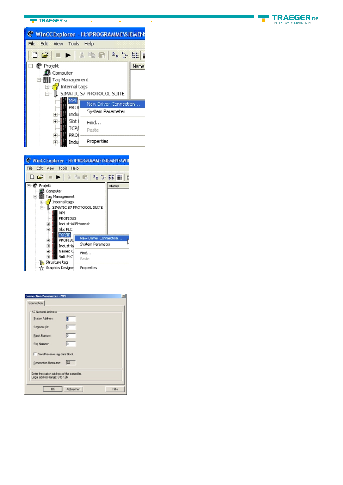
6. For a proper working communication with the PLC there must be defined how the software has to
Configure the interface as described in Set PD/PC-Interface.
communicate with the PLC Therefore you have to right-click on “Tag Management” it opens the context
1. Start WinCC by using the desktop link or the program entry in the start menu.
menu. Choose “New Driver Connection … “.
2. Choose „New” in the menu „File” or click on the white („letter”) symbol to start a new project.
7. In the „Add new driver“ dialog select the driver which fits to your PLC For a S7 PLC choose „SIMATIC S7
Protocol Suite.chn“. If you want to use an other PLC please inform yourself first, which driver fits with your
PLC.
It is very important that the selected driver fits with the PLC otherwise the connection cannot be
3. The next dialog offers you several project types “Single-User Project”, “Multi-User Project” and “Client
established..
Project”. The next steps are the describing for the “Single- User Project”.
8. You should see now in the Explorer under the branch “Tag Management” the branch “SIMATIC S7
PROTOCOL SUITE”. Expand the branch and many protocols for various compounds will appear. The General
way of proceeding a new connection is to: Right-click on the desired connection (MPI - > Picture: “MPI“,
TCP/IP - > Picture: “TCP/IP“). A context menu opens. Click on „New Driver Connection…”. This manual
describes the connection configurations for MPI and TCP/IP
MPI
4. “OK” leads you to a new dialog. Type in the “Project Name” and the “Subfolder” of the project path. The
chosen configuration is confirmed with “Create”.
S7-USB user manual 24 / 85 2019/10/05 05:07
Page 25
TCP/IP
Söllnerstr. 9 92637 Weiden info@traeger.de +49 (0)961 48 23 0 0
6.2.4.1 MPI Configuration
9. Now you are able to type in the name of the connection. With a click on “Configuration“ a new dialog
will appear. Now you are able to set the properties of the connection. Set up the station address of the PLC
(in this example “2“). Confirm with “OK” until you are back to the main window. Read further
”Communication and fault diagnosis “ .
S7-USB user manual 25 / 85 2019/10/05 05:07
Page 26
Söllnerstr. 9 92637 Weiden info@traeger.de +49 (0)961 48 23 0 0
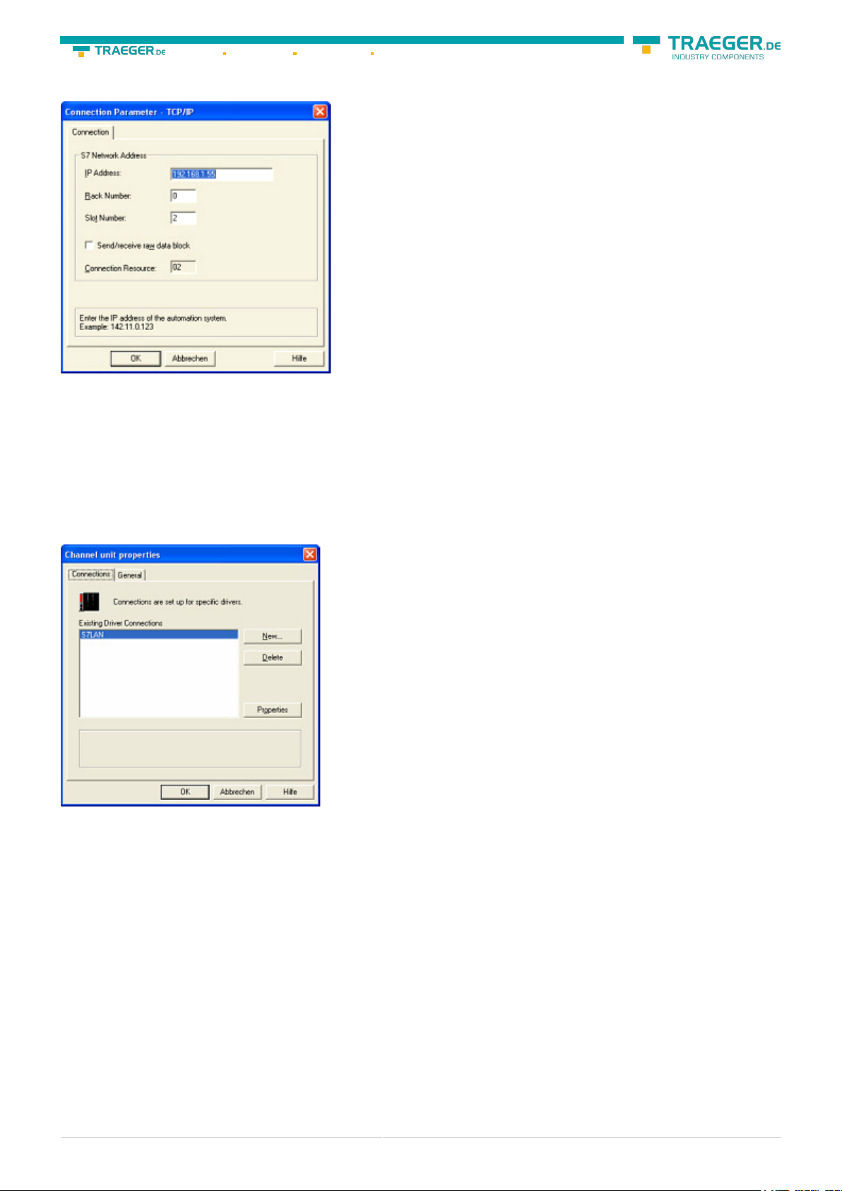
6.2.4.2 TCP/IP Configuration
10. A dialog appears where you can configure the connection parameters. Set up the IP - Address of the
module and configure the rack number as well as the slot number. Confirm this configuration by clicking
“OK”. Example configuration:
IP - address 192.168.1.55
Rack - Number: 0
Slot - Nr.: 2
11. With a right-click on the new connection you can start the properties dialog. In this dialog please click
on properties.
12. In this “Channel unit properties” you are able to see all “available connections”. Choose the latest
created connection and click again on „Properties”. Now you can see all the variables which has been
created for this connection. In fact this connection is a new connection so there should not be any variable
in the list. To add a new variable click on „New”.
13. Now you are able to set up the name of the variable and different more properties. In our example, we
assign the following values: Name: „S7LAN_MW0“
Data type : „unsigned 16 - Bit value“
Length: „2“
Address: „MW0“
Format adaptation: „WordToUnsignedWord“ Click on „Choose” beside the Address to define the address
from the variable.
Example configuration: The data area from the variable is set to „Mark“ and the address is set to „Word”.
The edit box „MW“ is set to „0”.
14. Confirm all open dialogs with „OK“ until you reach the main window.
15. The connection needs to know which network interface card it should be used to send data via the
S7-USB user manual 26 / 85 2019/10/05 05:07
Page 27

Söllnerstr. 9 92637 Weiden info@traeger.de +49 (0)961 48 23 0 0
Ethernet. Open the “System parameters“dialog from the context menu (right-click on TCP/IP).
16. Choose from the registry card „Unit“ and set the “logical device name“ to your network interface card
(usually the name of the NIC begins with a „TCP/IP - > „).
17. Confirm with „OK“.
18. Now you are able to start the communication. Stop it by clicking on .
6.2.4.3 Communication and fault diagnosis
To clean up errors faster the WinCC Software offers a tool named “Channel Diagnosis”. This tool analyses
all connections from your WinCC software. For demonstration purposes please stop the last started
connection from your WinCC explorer.
19. Start the software “Channel Diagnosis“ by using your link in the start menu.
20. The tool could not detect a running connection so it marked the connection/s with a red ‘X’ (registry
card “Channels/Connections“). Click on the last created, not active connection (with the red ‘X’) and some
informations from the connection will appear in the right part of the dialog. One of these counters is called
“Last Error Code“.
S7-USB user manual 27 / 85 2019/10/05 05:07
Page 28

Söllnerstr. 9 92637 Weiden info@traeger.de +49 (0)961 48 23 0 0
21. If you take a right-click on the error value a window opens with “Help”. Click on the “Help” window and
a yellow window appears (tooltip) with detailed error descriptions.
22. Lets see what happens if the connection runs properly. Start the connection from your WinCC Explorer.
The “Channel Diagnosis“dialog marks the connection with a green hook if everything worked out.
6.2.5 Windows Control Center flexible 2004 (WinCC
flexible) (v5.2.0.0)
Please make sure that the interface configuration is correct as described in PD/PC-Set interface
1. Start the WinCC flexible 2004 software by using the desktop link or the program entry in the start menu.
2. First you need to select “Create an empty project” on your first page.
S7-USB user manual 28 / 85 2019/10/05 05:07
Page 29

Söllnerstr. 9 92637 Weiden info@traeger.de +49 (0)961 48 23 0 0
3. In the “Device selection“mark the used operator panel (example: “TP 170A“) confirm with “OK“.
4. After the project has been created right-click in the project window on “Connections“of the sub menu
“Communication“. In the context menu click on “Add Connection“.
5. A new configuration window “Connections” opens in the right part of the main window. This offers you
different setting options. Important for the connection is:
⇒ the communication driver (set up which PLC you are using (example: “SIMATIC S7 300/400“))
⇒ the Baud rate (Set this on “187 500”)
⇒ the address of the terminal (HMI) (in this example “1“)
⇒ the Profile (“MPI“ for example)
⇒ the Highest Station Address (HSA) (e.g. “126“)
⇒ the address of the PLC (e.g. “2“)
S7-USB user manual 29 / 85 2019/10/05 05:07
Page 30

Söllnerstr. 9 92637 Weiden info@traeger.de +49 (0)961 48 23 0 0
6. Now you can start with your work. If you have finished work you can transfer this project to the panel by
reading the next steps.
7. Choose „Transfer Settings“ from the sub menu „Transfer”.
8. In the new dialog change the „Mode“ to „MPI/DP“ and set the „Station address“ of the operator panel
(e.g. „1“). If desired you can switch the „Delta transfer“ to „On” (in this example we set it „Off”).
9. Press the button „Transfer“ to start communication with the terminal. Your project is about to be
transferred. The WinCC flexible software is now able to communicate with your operator panel.
6.2.6 ProTool/Pro v6.0 SP2
Please be sure that the interface configuration is correct as described in PD/PC-set interface
1. Start ProTool/Pro by using the desktop link or program entry in the start menu.
2. Choose from the menu „File“ the sub menu „New“ or click on the right symbol.
3. The next dialog let you select which operator panel you are using. Mark the used panel (e.g. „TP 170A“)
S7-USB user manual 30 / 85 2019/10/05 05:07
Page 31

Söllnerstr. 9 92637 Weiden info@traeger.de +49 (0)961 48 23 0 0
4. „Next“ leads you to a new dialog. Type in the specific fields the name of the PLC device and choose the
used PLC in the driver selection (e.g. „SIMATIC S7 – 300/400 V6.0“).
5. Via „Parameter…“ you are calling an configuration dialog from the chosen PLC driver Set up the station
address of the panel (example „1“) and of the PLC (example „2“). Leave the point “Interface” in the
standard configuration. In the sector „Net parameter“ choose the interface which uses your module on the
PLC (e.g. „MPI“). Configure the baud rate to „187.5“.
6. The button „More …“ leads you to a small dialog where the „Highest Station Address“ should be
configured to „126“. Set up the „Number of masters“ (e.g. „1“)
7. confirm with „OK“ until you got back to the „Control Selection“.Go on with „Next“. 8. In the main window
start the Transfer Settings dialog by clicking on „File“ „Transfer“ „Settings…“. Choose „MPI / PROFIBUS DP“
from the listbox and type in the station address of the operator panel (e.g. „1“). Confirm with „OK“. and
start with your work If you have finished working on this project you can go on with the next steps.
S7-USB user manual 31 / 85 2019/10/05 05:07
Page 32

Söllnerstr. 9 92637 Weiden info@traeger.de +49 (0)961 48 23 0 0
9. If you want to transfer you project to the panel you have to generate the project first. This can be done
with a click on „File“ -„Compile“.
10. To transfer the project just click on „File“ „Download“ „Start Project Download“ or click on the right
symbol .
Please wait while the project is transferred. The communication between the operator panel is now
established.
6.2.7 Microwin v3.2 (only for S7 200)
Please be sure that the interface configuration is correct as described in PD/PC-set interface
1. Start Microwin using the desktop link or program entry in the Start menu.
2. Click on „Type“ in the menu „PLC
S7-USB user manual 32 / 85 2019/10/05 05:07
Page 33

Söllnerstr. 9 92637 Weiden info@traeger.de +49 (0)961 48 23 0 0
Configure the „PLC Type“ (e.g. „CPU 224“) as well as the „CPU Version“ (e.g. „01.22”) to the dialog.
3. Click on „Communications…” to start the next dialog. In the sector „Address” set up the „Remote”
listbox with the station address of the PLC (e.g. „2”).
If you skipped the point b („ PD/PC-set interface“) you can configure the PG/PC interface with a click on
„Set PG/PC interface“.
4. In the right part of the dialog double click on the blue arrow symbol to test the communication with
S7-USB user manual 33 / 85 2019/10/05 05:07
Page 34

Söllnerstr. 9 92637 Weiden info@traeger.de +49 (0)961 48 23 0 0
the PLC.
5. The sector „Address“ should be updated and displays the „PLC Type”. Also the CPU of the PLC is
displayed in the right part of the dialog.
6. Confirm with „OK“ until you get back to the main window. The communication with the PLC ist now
established.
6.2.8 Microwin v4.0 in PPI-Multimaster-Mode
1. The PPI-Multimaster-Mode was developed that more devices can communicate parallel with one PLC.
The following steps describe how to configure this mode in hardware and software.
2. The module or cable has to switched in the PPIMulti-Mode. This mode can be switched in the menu-tree
under „Generally“ and „Bootconfiguration“
3. There you have to select „PPIMMaster“ and confirmed with „Saving“.
For LAN-devices you can do this in the integrated WebServer, also.
4. Now, you have to configure the PG/PC - Interface. This could you also do within the Microwin-Software.
5. Start your Microwin-Software.
6. Click on the button „Set PG/PC-Interface“ under „View“ in the left down part of the window.
7. Select the entry „PC/PPI cable(PPI)“ and click on the button „Properties“.
S7-USB user manual 34 / 85 2019/10/05 05:07
Page 35

Söllnerstr. 9 92637 Weiden info@traeger.de +49 (0)961 48 23 0 0
8. In the menu „PPI“ you are able to configure diverse settings like for e.g. “HSA“.
S7-USB user manual 35 / 85 2019/10/05 05:07
Page 36

Söllnerstr. 9 92637 Weiden info@traeger.de +49 (0)961 48 23 0 0
9. In the menu “Local Connection“ you select the com-port “Interface to“ to the port which is served from
the tool PLCVCom. 10. Click on the button “OK“ and click in the left down area in your windows on
„Communikations“.
11. Click double on “Double-Click to refresh“. The PLCs would be searched.
S7-USB user manual 36 / 85 2019/10/05 05:07
Page 37

Söllnerstr. 9 92637 Weiden info@traeger.de +49 (0)961 48 23 0 0
12. When the PLC was found, the picture changes it like this:
13. Prove the dialog with „OK“ until you would be in the main window. The communication to the PLC is
now ready.
6.2.9 S7 for Windows v5.02
1. Start the „S7 for Windows” software by using the link on your desktop or use the link in your start menu
(standard is „Programs\S7 for Windows\S7 for Windows“)
S7-USB user manual 37 / 85 2019/10/05 05:07
Page 38

Söllnerstr. 9 92637 Weiden info@traeger.de +49 (0)961 48 23 0 0
2. Choose File - >Preferences… to configure the communication configuration between the computer and
the PLC. A new dialog appears which provides to set up a lot of configuration data about the
communication with your PLC.
3. Choose the first registry card „Interface“ (standard) and set up the configuration data as described
below:
⇒ Area: „Preferences from:“ ⇒PC
⇒ Area: „PLC Type:“ ⇒ S7
⇒ Area: „Protocol:“ ⇒ MPI - Umsetzer
⇒ Area: „Serial Port:“
⇒ Choose the virtual COM port which has been created by PLC - VCom (e.g. „COM 4”).
⇒ Area: „Baud Rate“ ⇒ Choose the speed you want to use at the bus (e.g. „115200“)
⇒ Area: „MPI Converter:“ - Activate the checkbox „Only Master at the Bus“ if you have only one PLC in the
bus.
- Leave the fields „ S7W MPI Address“ and „MPI Address PLC“ as it is.
S7-USB user manual 38 / 85 2019/10/05 05:07
Page 39

Söllnerstr. 9 92637 Weiden info@traeger.de +49 (0)961 48 23 0 0
- The number in the listbox „Max MPI Address“ must be higher than the PLC with the highest station
address in your MPI bus. Otherwise every PLC which is higher than this number will not been seen (e.g. if
there is only one PLC in your bus „15“ is more than enough).
4. After the software is configured , please click „Select PLC” in the area „MPI Converter“. A new dialog
appears where you can select the desired PLC
5. The dialog displays all the PLCs that can be found in your MPI bus. Select the desired one and confirm
with „OK”.
6. Close the preferences dialog by pressing the „OK“ button.
7. Back in the main window press the „PC Block List“ button for testing the new established
communication configuration.
8. Please wait a moment for the software to read the desired blocks from the PLC. The blocks will be
displayed in the listbox below the menu bar (see picture to the right).
S7-USB user manual 39 / 85 2019/10/05 05:07
Page 40

Söllnerstr. 9 92637 Weiden info@traeger.de +49 (0)961 48 23 0 0
The communication between the software and your PLC is established.
6.2.10 Direct setting of a slave address to a passive
Profibus-Slave
With the S7-LAN-module or MPI-LAN-cable and Step7-direct-driver V1.21 (or later) and the MPI-II-cable
(only with USB) or S7-USB and Step7-direct-driver V1.22 (or later) is it possible to give a directly connected
Profibus-Slave a bus-address.
Important here is that the subscriber is connected directly to the S7-interface and the external supply of
24V DC is also connected. In the Step7-direct-driver must then in the properties set that “PD/PC is only
master”. There is no another note in this case, you will use this function as if you are connected with your
PD to the module.
7 S7-Interface Configurator Help
Language selection
User interface
Bus configuration
Network settings
Parameterize TELEService
Index "Network"
Index "Modem"
Index "Serial Parameter"
Index "Access Protection"
Index "GSM/ISDN/SMS"
Index "Internet/Mail"
S7-USB user manual 40 / 85 2019/10/05 05:07
Page 41

Söllnerstr. 9 92637 Weiden info@traeger.de +49 (0)961 48 23 0 0
Tuning
Factory defaults
PPI Boot off
Emergency-Loader
7.1 Language selection:
Select the menu Configuration to change the language permanently:
7.2 User interface:
Select near Search which interfaces are searched permanently for devices.
You could choose:
• Serial All existing COM-Ports are scanned for devices
• USB Search devices which are connected by USB
• LAN Search devices on all network-cards
The button Search starts a parallel search on all selected interfaces.
After selecting a updateable device the button Update gets available.
Below the buttons is a list of the found devices. In each line an image, the type of the device, name (if
existing), interface, serial number (if possible) and the OS-version of the device is displayed. On the
rightmost position the actual OS-version on the harddisk is displayed.
The background of the lines could use the following colours:
• White The OS of the device is up-to-date
S7-USB user manual 41 / 85 2019/10/05 05:07
Page 42

Söllnerstr. 9 92637 Weiden info@traeger.de +49 (0)961 48 23 0 0
• Light blue The OS of the device is not up-to-date, the device could be updated
• Red An error occured by accessing the device
• Yellow Update is in progress for this device
• Dark blue Selected device
Double click onto a device which could be updated shows the version-documentation of the device (only
available in German):
The button Update with FD updates the OS of the device and sets the factory default.
The button Bootstrap sets the firmware/configuration to factory default.
The button Factory defaults sets the configuration to factory default.
The button Parametrize activates a dialog regarding to the device:
Overview:
Device Dialog
TELEService
MPI / PPI - Profibusmodem
Parametrize TELEService
MPI/PPI Parametrize TELEService
MPI-II
MPI-USB
Choices:
Bus configuration
Parametrize TELEService
S7-USB Bus configuration
S7-LAN
MPI-LAN
Choices:
Bus configuration
Network settings
The button PPI Boot off disables the PPI boot option of a serial connected device.
The button Emergency-Loader tries to repair LAN products which are in emergency-loader mode.
The button Tuning activates a dialog for special parameters.
The button Exit leaves the application.
S7-USB user manual 42 / 85 2019/10/05 05:07
Page 43

Söllnerstr. 9 92637 Weiden info@traeger.de +49 (0)961 48 23 0 0
7.3 Bus configuration
To Parametrize the connection to the device, select a device and click “Parametrize”.
Regarding to the device you maybe have to click on the button Bus configuration (see Parametrize
table).
Here you can Parametrize the following:
Use bus config for PC Tooks the bus configuration from the PC
Baud rate chooses the Baudrate for the cable to bus communication
The highest station-address in the bus
Highest station address
PD/PC is the only master on
the bus
Profile Bustype of the connection
Local client address
Protocol type Protocol type of the connection
Boot settings Boot setting of the connection
(the less you use, the more performance on the MPI-bus,
must be corresponding with the configuration in the CPU’s)
The TS-Adapter is the one and only master in the MPI-bus
(adapter hast to speak to all passive clients)
Which local station-address is used for the TS-Adapter.
Please consider that a programming device has normally the number 0,
operator panel have 1, CPU’s use 2, FM/CP’s 3 etc.
Please: Never use the same station-number for 2 different stations!
7.4 Network settings
Here you can set the network configuration of the selected device:
S7-USB user manual 43 / 85 2019/10/05 05:07
Page 44

Söllnerstr. 9 92637 Weiden info@traeger.de +49 (0)961 48 23 0 0
• Factory default This button sets all over the network reachable devices to factory default.
• DHCP-client active When set the device acts as DHCP-client.
• IP address
• Subnetmask Here you could enter the Subnetmask of your network.
• Gateway address Here you could enter the IP address of your Gateway. Usual a router address.
• Device name Here you could change the device name.
Factory default:
• DHCP-client active not set
• IP Address 192.168.1.56
• Subnetmask 255.255.255.0
• Gateway address 0.0.0.0
• Device name empty
Here you could enter the IP Address over which the device is accessed in the
network.
7.5 Parametrize TELEService
To Parametrize the device, first click on the device, after that on “Parametrize”.
S7-USB user manual 44 / 85 2019/10/05 05:07
Page 45

Söllnerstr. 9 92637 Weiden info@traeger.de +49 (0)961 48 23 0 0
Regarding to the device, you maybe have to click on the TELEService button.
After clicking on “TELEService” a message will show up:
Depending on the version of your TELEService software choose Yes or No.
The regular parameters can be changed manually in the following categories:
7.5.1 Index "Network":
Here you can configure following:
S7-USB user manual 45 / 85 2019/10/05 05:07
Page 46

Station related:
Söllnerstr. 9 92637 Weiden info@traeger.de +49 (0)961 48 23 0 0
PD/PC is the only master on
the bus
Address
Network related:
Network type The network type MPI or PROFIBUS
Transmission rate The transmission speed on the MPI bus
Current transfer rate Shows the current transfer rate of the device
The highest station address in the bus
Highest station address
(the less you use, the more performance on the MPI bus, must be
corresponding with the configuration in the PLC’s)
The TS-Adapter is the only master on the MPI-bus
(adapter must speak to all passive clients)
Which local station-address is used for the TS-Adapter.
Please consider that a programming device has normally the number 0,
operator panel have 1, CPU’s use 2, FM/CP’s 3 etc.
Remind: Never use the same station-number for 2 different stations!
7.5.2 Index "Modem":
In this dialog you could configure the modem related setup.
Modem Settings:
The initialization string consists of several commands to the modem:
AT ⇒ start command
&F ⇒ use factory settings
E0 ⇒ echo off
Initialization
Hang up
Location:
S7-USB user manual 46 / 85 2019/10/05 05:07
L1 ⇒ volume of speaker is low
M1 ⇒ speaker is on at connection
Q0 ⇒ output of the return values
V1 ⇒ return values plain text
&C1 ⇒ DCD shows status of the carrier sound
S0=1 ⇒ automatic connection after 1 ring
The deselection text is made up of 2 parts:
+++ ⇒ Switch to command mode
AT ⇒ start command
H ⇒ Hang up connection
Page 47

Söllnerstr. 9 92637 Weiden info@traeger.de +49 (0)961 48 23 0 0
Dialing method
Official number
To access an outside
line, first dial
Call Preferences:
There are two possible call techniques:
MFV tone, the telephone number is transferred by several frequencies
IWV pulse, the telephone number is transferred with the amount of several
pulses on the line
If you need a prefix before your number to establish a call outside, you must
enter the prefix here e.g. 0.
Wait for dial tone before
dialing
Number of redial
attempts
Redial after
In case the modem should wait for a free line, you should set the
corresponding checkbox.
At number of retries you could configure the number of retries for a
connection before the call is stopped.
Using a retry you could enter the seconds the application should wait
between calls.
7.5.3 Index "Serial parameter":
In this dialog the transfer rate between modem and TS-Adapter is selected.
Connection Preferences:
Transfer rate
Parity
The transfer-rate could be selected between the following values:
2400, 4800, 9600, 19.2k, 38.4k, 57.6k and 115.2kBaud
The parity could be selected, but this is modem depended because some modems could
not handle the parity bit:
None: (There is no parity testing)
Odd: (The amount of bits set to 1 is odd)
Even: (The amount of bits set to 1 is even)
7.5.4 Index "Access Protection":
The access over a telephone line could be configured in this dialog.
Access Protection:
The administrator can change the configuration over a telephone line. The two user accounts can not
change the configuration.
S7-USB user manual 47 / 85 2019/10/05 05:07
Page 48

Söllnerstr. 9 92637 Weiden info@traeger.de +49 (0)961 48 23 0 0
The username is maximal 8 characters long. Every user and the administrator should use a password
which is used to login in the TELEService over a telephone-line.
After three failed retries the connection is hanged up, so you must call again (not like the original TSadapter).
After changing the password for a user/administrator you must re-type it again correctly.
You can enter a callback number which is used for a callback from the TS-adapter. After you dialed the
number of the TS-adapter, you are asked for username and password. In case the username and password
is valid, the connection is hang up and the TS-adapter calls back the configured callback number.
7.5.5 Index "GSM/ISDN/SMS":
Information about the three different devices:
Analog Modem:
Type You could choose the location of the modem.
ISDN Modem:
Type Choose the type of the ISDN network:
AT&T 5ESS Nothern Telecom DMS-100 EuroISDN NET3 (Standard) INS64 US NI-1 VN4 Protocol Choose the
transfer protocol type:
Modem like V.120 X.75 (Standard) ML-PPP SoftBonding HDLC CLEAR MSN Multiple Subscriber Number is
used for all ISDN channels. If empty no MSN is used.
GSM Modem:
S7-USB user manual 48 / 85 2019/10/05 05:07
Page 49

Söllnerstr. 9 92637 Weiden info@traeger.de +49 (0)961 48 23 0 0
PIN PIN number of the SIM card, up to eight numeric characters (only for TELE-SERVICE GSM).
With the button „Provider“ the provider could be chosen. Read the list of providers could be
elapse more than a minute. In the end the possible provider are listed for selection.
With „Automatic“ the GSM-Modem tries to connect automatically to a provider. On the right side
of the button, the actual used selection is displayed.
Display Description:
Provider
Automatic: The provider is automatically searched and selected from the GSM-modem.
Manual: The Provider is selected manually from the GSM-Modem
no network registered: No connection to the GSM-network, the receive-quality is too bad set
format: The format of the provider is set
Manual/automatic: The modem tries to select manually the provider, if this fails an automatic
search is done
unknown: Unknown response from GSM-Modem
The button „Refresh“ reads the signal strength from the modem, the quality is displayed.
Display Description:
Unknown: Unknown state of the GSM-network
no registration: The modem is not registered in the GSM network, no provider found
registration denied: Registration in the GSM-network is denied
Search network: In Search for a GSM-Provider
GSM: Attached to GSM
GSM(ROAMING): Attached to GSM, but with a Roaming-Partner. This could lead to high costs!
Refresh
The radio quality is displayed, together with the bit-error-rate.
Value Description:
99 No network, no receive
00 Very, very bad receive-quality
01 Very bad receive-quality
02 to 09 Bad receive-quality
10 to 17 Medium receive-quality
18 to 25 Normal receive-quality
26 to 30 Good receive-quality
31 Best receive-quality
Information about the rest of the Index GSM/ISDN/SMS:
S7-USB user manual 49 / 85 2019/10/05 05:07
Page 50

Söllnerstr. 9 92637 Weiden info@traeger.de +49 (0)961 48 23 0 0
SMS:
Switches:
NO SEND SMS RECEIVE SMS SEND+RECEIVE SMS DMTF CONFIRMATION SEND
SMS+DTMF CONFIRMATION RECEIVE SMS+DTMF CONFIRMATION
SEND+RECEIVE+DTMF CONFIRMATION SEND MAIL SEND MAIL+SEND SMS SEND
MAIL+RECEIVE SMS SEND MAIL+SEND+RECEIVE SMS SEND MAIL+DTMF
SMS
CONFIRMATION SEND MAIL+SEND SMS+DTMF CONFIRMATION SEND
MAIL+RECEIVE SMS+DTMF QUITTUNG SEND MAIL+SEND+RECEIVE+DTMF
CONFIRMATION
Attention: before setting ON check configuration, after activating the device
will go on the MPI bus and tries to connect to the defined PLC.
Receive of SMS only with TELEService-GSM Receive of DTMF only with
TELEService GSM
Bus address TS local station address (should not be used twice in the MPI/Profibus!)
Bus address CPU
Communication flag
word
Communication data
block
from this station address the flag word and data block is accessed for
communication
communication-flagword (the first byte is the command, the second is the
state). Use even operand-addresses.
Address of the CPU in the Bus
Configure the SMS-Provider to use, including type, phone-number and charcode.
Provider 0/1/2/3
First Input: Choose a type of the transmission.
Second Input: Telephone number or email address.
Third Input: Choose a character encoding.
NTP-Server Input for an Network Time Protocol - Server
Error analysis:
The possible error conditions for the modem, mpi bus problems or other problems are displayed in this
text-field.
First the modem-related information is shown:
Message
S7-USB user manual 50 / 85 2019/10/05 05:07
Page 51

Söllnerstr. 9 92637 Weiden info@traeger.de +49 (0)961 48 23 0 0
Modem ready
Modem error
No answer from modem
Modem detects ring
End of connection
connected via modem line
No dialtone detected
Phone-line or telephone busy
Phone-number is blacklisted in modem
Phone-number delayed
Access denied for 1 minute
Fax-call detected
Data-call detected
unknown error
The selected direct-access-number not configured
The configured PIN-Number is wrong for the inserted SIM-Card
The SIM-Card is not or wrong inserted or the SIM-Card is a 5V Type
Possible MPI-Bus error-messages
MPI/Profibus-Configuration erroneous
Timeout at MPI/Profibus detach from device
The local station-address is used twice in the MPI/Profibus
A20/M20/TC35 Modem operation
The MPI/Profibus is not correctly configured
The HSA is not configured optimal
The MPI/Profibus-Baudrate is not detectable
Overflow in the internal MPI-Readbuffer
Overflow in the internal LAN-Readbuffer
Overflow in the serial Buffer
The selected MPI/Profibus-Baudrate is wrong
Overflow in internal LAN-Writebuffer
LAN-Receive-Error
LAN-Send-Error
The PD-Number is wrong
The transferred SAP is wrong/unknown
ErrCode 01: The Destination address (XXX) of a State protocol > 127 detected. In the MPI/ProfibusBus there are no stations possible which station number is greater than 127. (FC=YYh)
ErrCode 02: At state-protocol the Source-Address is detected as 127. This is the Broadcast-address
which is not possible.
ErrCode 03: The received State protocols destination address (XXX respectively YYY) does not exist
in the MPI-Bus. (FC=ZZh)
ErrCode 04: The function-code (YYh) of the received State protocol from XXX is incorrect. The 7th Bit
is High, but according to the specification the Bit has to be low.
ErrCode 05: A State protocol has been received. But the function-code (YYh) means that the
participant is not ready to enter the bus.
ErrCode 06: The function-code in the State-protocol received from XXX is unknown (FC=YYh)
ErrCode 11: The sender (XXX) of the received data-protocol is unknown. To send data the participant
must get the Token. (SSAP=YYh, FC=ZZh, length=UUU)
ErrCode 12: Data-protocol with Source-address 255 (Broadcast) is useless. (CPU=XXX, SSAP=YYh,
S7-USB user manual 51 / 85 2019/10/05 05:07
Page 52

Söllnerstr. 9 92637 Weiden info@traeger.de +49 (0)961 48 23 0 0
FC=ZZh, length=UUU)
ErrCode 13: The sender (XXX) of the received data-protocol is unknown. To send data the participant
must get the Token. (SSAP=YYh, FC=ZZh, length=UUU)
ErrCode 14: The 7th Bit of the function-code is High, but according to the specification the Bit has to
be low. (CPU=XXX, SSAP=YYh, FC=ZZh, length=UUU)
ErrCode 15: The upper 4 Bit of the Function-code are wrong/unknown) (CPU=XXX, SSAP=YYh,
FC=ZZh, length=UUU)
ErrCode 16: Unknown function-code has been transmitted to the cable. (CPU=XXX, SSAP=YYh,
FC=ZZh, length=UUU)
ErrCode 17: Destination-SAP are defined till 3Fh in data-protocols. (CPU=XXX, SSAP=YYh, FC=ZZh,
length=UUU)
ErrCode 18: Source-SAP are defined till 3Fh in data-protocols. (CPU=XXX, SSAP=YYh, FC=ZZh,
length=UUU)
ErrCode 19: Received a data-protocol with destination-SAP=0, Connection request from another busparticipant with our cable. (CPU=XXX,SSAP=YYh,FC=ZZh,DSAP=UUh)
ErrCode 1A: Participants are sending data to our cable with source-SAP = 0, which means that the
participant has not made a connection establishment or has lost the negotiated SAP.
(CPU=XXX,SSAP=YYh,FC=ZZh,DSAP=UUh)
ErrCode 1B: Data-protocol with unknown data-function-code received.
(CPU=XXX,SSAP=YYh,FC=ZZh,DFC=UUh)
ErrCode 1C: Data-protocol with unknown data-function-code received.
(CPU=XXX,SSAP=YYh,FC=ZZh,DFC=UUh)
ErrCode 1D: Received a state-protocol with error-code. (CPU=XXX,FPGA=YYh,RAM=ZZh)
ErrCode 1E: FPGA has caused an interrupt although no data present.
(SD1=XXh,SD1=YYh,CPU=ZZZ,FC=UUh)
ErrCode 20: Unknown protocol at PPIMultimaster-Mode. (FC=XXh,Length=YYY)
ErrCode 21: Unknown baud-rate at PPIMultimaster-Mode. (Baudrate=XXh)
After that additional hints are displayed.
7.5.6 Index "Internet/Mail":
The internet connection is configured by PPP, often a username and password is needed. Define them in
“Internet access over PPP”.
Attention: This is NOT the username and password of your E-Mail-account!
In the next section “Mail” the E-Mail-account is defined:
Internet access over PPP:
Username Username for the Internet access
Password Userpassword for the Internet access
S7-USB user manual 52 / 85 2019/10/05 05:07
Page 53

Söllnerstr. 9 92637 Weiden info@traeger.de +49 (0)961 48 23 0 0
Mail:
Server
Mail from
Username
Password Password for the E-Mail-Account
Source-E-Mail-Address
(should be from the same Free-mailer, instead a delivery is often not possible)
Name of the User-account
(often the E-Mail-address or Customer-number)
7.6 Tuning
This menu is only used in some special cases.
Select the device and click the button “Tuning” and after that the following dialog is displayed:
The following configuration is possible, it will be transferred to the Cable by pressing the button „OK“.
The configuration is saved permanently in the Flash-ROM:
At ProTool RT the communication could break down, because the MPI-Cable is
Delay before send
S7-USB user manual 53 / 85 2019/10/05 05:07
transferring the answer-protocol to fast. In this case you could insert a time in
0.1ms ticks. Insert at first 300, to great values are preventing the
communication.
Page 54

Söllnerstr. 9 92637 Weiden info@traeger.de +49 (0)961 48 23 0 0
Some Touch-panels has the problem, that when they get a wrong version-
HMI-Cable version
A20-Terminal
Show ErrCode
messages in display
Boot settings:
Normally the MPI-Cable automatically selects the correct bus type, no changes are needed. In specialcases the MPI-Bus could be selected as PPI.
For example: This application and the PLC are powered on at the same time. The application is
communicating immediately with the cable, the PLC is booting, in this case the MPI-Bus is not running. The
MPI-Bus is erroneous, so no communication is starting. If this occurs you could choose, that the cable is
working as MPI-Adapter only.
Language:
You could select the language which is used on the cable (German or English).
S5 on MPI mode off:
Deactivates temporary the “S5 on MPI” function, the cable doesn't poll the bus anymore.
information they never retry to connect (and then the correct version is
transferred). In this case the HMI-version-information could be transferred
immediately.
Shows error messages on the display of the connected device
send reset to cable:
Send reset to cable.
Console:
Shows some information about the status of the connection.
7.7 Factory defaults
This button sets the configuration of the selected device to factory defaults.
7.8 PPI Boot off
In PPI boot mode S7IFC cannot communicate with the cable. To disable the PPI boot mode, click on the
button PPI Boot off. In the following dialog you must select the serial port where the cable is connected:
S7-USB user manual 54 / 85 2019/10/05 05:07
Page 55

Söllnerstr. 9 92637 Weiden info@traeger.de +49 (0)961 48 23 0 0
7.9 Emergency-Loader
LAN products running in emergency-loader are automatically found by S7IFC:
After a click on Emergency-
Loader the following dialog appears:
S7-USB user manual 55 / 85 2019/10/05 05:07
Page 56

Söllnerstr. 9 92637 Weiden info@traeger.de +49 (0)961 48 23 0 0
On a click on Yes the emergencyloader tries to run the main program of the firmware.
On a click on No the emergency-loader tries to rewrite the complete firmware.
8 MPI cable manager
8.1 Description
The MPI cable manager allows you to install an update in your cables and modules and configure them.
The MPI cable manager can be used for the following products:
• MPI-LAN cable– Art. ID. 9352-LAN
• S7-LAN module– Art. ID. 9352-LANCon
• MPI-USB cable– Art. ID. 9352-USB
• S7-USB module– Art. ID. 9352-S7-USB
• MPI-II cable (USB – operation) – Art. ID. 9352 + 9352.1
• MPI/PPI cable– Art. ID. 9350
• Tele-Service – Art. ID. 9377-(ANALOG/ISDN/GSM)-OP
• MPI/PPI-profibusmodem – Art. ID. 9379-(G)-OP
8.2 Installation
1. Download the MPI-Kabelmanager from the product-page of your MPI-product and start the installation.
S7-USB user manual 56 / 85 2019/10/05 05:07
Page 57

Söllnerstr. 9 92637 Weiden info@traeger.de +49 (0)961 48 23 0 0
2.Following the Language selection the installation starts and a welcome-screen is displayed. Next click
onto the button „Next“. To change the installation path, click on “Browse”. Then click “Continue”.
3. Select in this dialog the program folder for the MPI cable manager startup items. Then click “Continue”.
S7-USB user manual 57 / 85 2019/10/05 05:07
Page 58

Söllnerstr. 9 92637 Weiden info@traeger.de +49 (0)961 48 23 0 0
4. Wait for the installation of the files. 5. End the installation after a successful copy of data with “Finish”.
8.3 Overview
8.3.1 Language
After
starting the application the tab Language is displayed at first:
S7-USB user manual 58 / 85 2019/10/05 05:07
Page 59

Söllnerstr. 9 92637 Weiden info@traeger.de +49 (0)961 48 23 0 0
In this Dialog you could choose the used language in the application.
You could choose between German and English and confirm by clicking on the desired language.
8.3.2 Interface
In „set interface“ you can choose the COM-port you device is connected at. Only the COM-port which was
aktive at starting the MPI-Kabel-Manager are shown.
„Search“ update the COM-port listed in „set interface“ and put the Kabelmanager to the respective COMport.
For access query choose „Direct“ if your product connects via USB-cable or Nullmodem-cable. „Modem“ if
your product connects via telephone line or „TELE-Network“ if your product connects with a TELE-Network
device via telephone line. The bars below shows at which COM-port something was found or not.
8.3.3 Update
S7-USB user manual 59 / 85 2019/10/05 05:07
Page 60

Söllnerstr. 9 92637 Weiden info@traeger.de +49 (0)961 48 23 0 0
The diskette show the current operating system installed on your PC for corresponding product.
The cabel-symbol on the right show the operating system which is installed on your product at the
moment.
With the button „default settings“ you can set your products on default settings. Should the device be out
of order after configurated. This button is selectable after the version check.
With „Update“ you can install the current operating system. This button also is selectable after version
check.
With „version check“ your cable which is connected to the COM-Port reviewed.
The symbol next to version check shows the running update.
While update do not plug out the cable from the PLC or turn off the power supply (The cable
will lost all data)!
If the update is breaking before finished, it could be that the MPI-Cable displays in the first line of the LCD
„Load 1.50“ and in the second line „CheckUpd“. Close the MPI-Cable-Manger and restart it. After “check
version” (which could time about 30 seconds) and following „Update“ the broken update is restarted and
finished.
8.3.4 Teleservice
In this dialog the spezific configuration of the Tele-Service is taken. There are 3 Tabs, where the last one is
activated:
S7-USB user manual 60 / 85 2019/10/05 05:07
Page 61

Söllnerstr. 9 92637 Weiden info@traeger.de +49 (0)961 48 23 0 0
8.3.4.1 Telephone book
At the moment not implemented!
In this dialog you could define new elements or edit/erase existing elements in your telephone-book.
You could edit the following data:
⇒ Name for the connection (these are displayed at connection)
⇒ street
⇒ ZIP-code and country
⇒ Telephone number you can reach the TS-adapter
8.3.4.2 Connect
At the moment not implemented!
In this dialog the connection to another modem with a MPI-cable connected is started. Choose on the right
side the named connection, then press „connect“ to establish it.
With „Hang-Up“ you could stop an existing connection.
With the button „State“ the state of the connection is displayed at the lower side of the dialog.
8.3.4.3 Extra
S7-USB user manual 61 / 85 2019/10/05 05:07
Page 62

Söllnerstr. 9 92637 Weiden info@traeger.de +49 (0)961 48 23 0 0
In this dialog, all configuration to the TS-adapter is done.
The actual state of the MPI-cable is displayed right of the button “TS-function”, where the follwing 4
possible Messages could apear:
„TS-Adapterfunction is NOT activ. To activate press TS-function“
The MPI-cable acts like an PC-Adapter. There will no answer for TS-spezific protocols, the attached modem
will not initialized and the baud-rate to the PG/Modem is not fixed. The baud-rate is detected
automatically.
„TS-Adapterfunktion is ACTIVE. To disable press TS-function“
The MPI-cable acts like an TS-Adapter. There will an answer to TS-spezific protocols, the adapter could now
configured. An attached Modem will be initiliazed and the baud-rate to the modem is fixed.
„SNDERR“ or „RCVERR“
There is a communication error at sending or recieving data from the mpi-cable. Disconnect the MPI-cable
from the power supply (PLC). Change to the tab Connect and after that back to Extra. If the problem
remains, check the connection to the MPI-cable, especially the COM-port in the dialog interface.
With the buttons you could define which modem is used, activate or disable the TS-function or configure
the TS-adapter:
8.3.4.3.1 „Setup“
In the follwing dialog you could choose the used modem.
S7-USB user manual 62 / 85 2019/10/05 05:07
Page 63

Söllnerstr. 9 92637 Weiden info@traeger.de +49 (0)961 48 23 0 0
8.3.4.3.2 „TS-function“
With this button you select the function of the MPI-cable as TS- or PC-adapter. Right of this button the
actual state of the MPI-cable is displayed.
8.3.4.3.3 „configure adapter“
In the following dialog you could, after activating the MPI-cable as TS-adapter, configure the TS-spezific
setup.
Network
S7-USB user manual 63 / 85 2019/10/05 05:07
Page 64

Söllnerstr. 9 92637 Weiden info@traeger.de +49 (0)961 48 23 0 0
station related:
Here you can configure following:
The TS-Adapter is the one and only master in the MPI-bus
Which local station-address is used for the TS-Adapter. Please consider that a programming device has
normally the number 0, operator panel have 1, PLC’s use 2, FM/CP’s 3 etc.
Please: Never use the same station-number for 2 different stations!
network related:
Here you can configure following:
The Nettype MPI or PROFIBUS
The transfer-speed on the MPI-bus
The highest station-address in the bus (the less you use, the more performance on the MPI-bus, must be
corresponding with the configuration in the PLC’s)
Modem
S7-USB user manual 64 / 85 2019/10/05 05:07
Page 65

Söllnerstr. 9 92637 Weiden info@traeger.de +49 (0)961 48 23 0 0
In this dialog you could configure the modem-related setup.
The Init-String is composed out of several commands to the modem:
AT ⇒ start command
&F ⇒ use factory settings
E0 ⇒ Echo off
L1 ⇒ loudness of speaker is low
M1 ⇒ speaker is on at connection
Q0 ⇒ output of the return values
V1 ⇒ return values plain text
&C1 ⇒ DCD shows status of the carriersound
S0=1 ⇒ automatic connection after 1 ring
The Hang-Up-String is composed of 2 elements:
+++ ⇒ Change to command-mode
AT ⇒ start command
H ⇒ Hand-Up connection
There are 2 possible calling technics:
MFV tone, the telphone-number is transfer by several frequencies
IWV pulse, the telephone-number is transferred with the count of several pulses on the line
When you must a pre-call to establish a call outside your company, you could define it at Official number.
When the modem should wait for a free line, so you should set the corresponding checkbox.
At number of retries you could configure the number of retries for a connection before the call is stopped.
When using a retry you could choose the seconds which the application should wait between calls.
Serial parameter
S7-USB user manual 65 / 85 2019/10/05 05:07
Page 66

Söllnerstr. 9 92637 Weiden info@traeger.de +49 (0)961 48 23 0 0
In this dialog the transfer-rate between modem and TS-Adapter is selected.
The transfer-rate could choosen between the follwing values:
2400, 4800, 9600, 19.2k, 38.4k, 57.6k and 115.2kBaud
The Parity could be chosen, but this is modem-dependant because some modems could not transfer the
parity-bit:
None: (There is no parity testing)
Odd: (The number of one-bits are odd)
Even: (The number of one-bits are even)
Password
S7-USB user manual 66 / 85 2019/10/05 05:07
Page 67

Söllnerstr. 9 92637 Weiden info@traeger.de +49 (0)961 48 23 0 0
The Access over a telephone-line on the PLC could be configured in this dialog.
The Administrator could change the configuration over a telephone line, where an 2 User could not change
the configuration.
The User-Name is maximal 8 Chars long.Every user and the administrator could use a password which is
used to log into the PLC over a telephone-line. These have to enter for each new call.
After 3 wrong retries the connection is hanged up, so you must call again (Not so with an original TSadapter).
After changing the password for one user/administrator you must re-type it again correctly before it is
used.
In call-back-number you could define a telephone-number which is used for call-back from the TS-adapter.
After you connect with the TS-adapter, you are asked for your user-name and password. When the correct
password and user-name is transfered, the connection is hanged-up and the TS-adapter is calling back this
configured call-back-number.
GSM/ISDN/SMS
Analog modem:
You could choose the Location of the Modem.
ISDN modem:
S7-USB user manual 67 / 85 2019/10/05 05:07
Page 68

Söllnerstr. 9 92637 Weiden info@traeger.de +49 (0)961 48 23 0 0
Type: Choose the type of the ISDN-network switch:
AT&T 5ESS
Nothern Telecom DMS-100
EuroISDN NET3 (Standard)
INS64
US NI-1
VN4
Protocol: Choose the transfer-protocol-type:
Modem like
V.120
X.75 (Standard)
ML-PPP
SoftBonding
HDLC
CLEAR
DN/MSN: Directory Number resp. Multiple Subscriber Number Is used for both ISDN-channels. When using
the number 255 no DN/MSN is used.
GSM modem:
S7-USB user manual 68 / 85 2019/10/05 05:07
Page 69

Söllnerstr. 9 92637 Weiden info@traeger.de +49 (0)961 48 23 0 0
PIN: PIN-Number of the SIM-Card, up to 8 numeric chars, (only for TELE-SERVICE GSM).
Provider: With the button „Provider“ the provider could be choosen. Reading of the list of providers could
be elapse more than a minute. At end the possible provider are listed for selection. With „Automatic“ the
GSM-Modem tries to connect automatically to a provider. On the right side of the button, the actual used
selection is displayed.
Display Description:
Automatic: The provider is automatically searched and selected from the GSM-modem.
Manual: The Provider is selected manually from the GSM-Modem
no network registered: No connection to the GSM-network, the receive-quality is too bad
set format: The format of the provider is set
Manual/automatic: The modem tries to select manually the provider, if this fails an automatic search is
done
unknown: Unknown response from GSM-Modem
Refresh:
The button „Refresh“ reads from the Modem the receive quality, the quality is displayed.
Display Description:
Unknown: Unknown state of the GSM-network
no registration: The modem is not registered in the GSM network, no provider found
registration denied: Registration in the GSM-network is denied
Search network: In Search for a GSM-Provider
GSM: Attached to GSM
GSM(ROAMING): Attached to GSM, but with a Roaming-Partner. This could lead to high costs!
The Receive Quality is displayed, also as value together with the bit-error-rate.
Value Description:
99 No network, no receive
S7-USB user manual 69 / 85 2019/10/05 05:07
Page 70

Söllnerstr. 9 92637 Weiden info@traeger.de +49 (0)961 48 23 0 0
00 Very, very bad receive-quality
01 Very bad receive-quality
02 to 09 Bad receive-quality
10 to 17 Medium receive-quality
18 to 25 Normal receive-quality
26 to 30 Good receive-quality
31 Best receive-quality
Messages:
The possible error conditions for the modem, mpi-bus-problems or other problems are displayed in this
text-field. Firstly, the modem-related information is shown:
Message
Modem ready
Modem error
No answer from modem
Modem detects ring
End of connection
connected via modem line
No dialtone detected
Phone-line or telephone busy
Phone-number is blacklisted in modem
Phone-number delayed. Access denied for 1 minute.
Fax-call detected
Data-call detected
unknown error
The selected direct-access-number not configured
The configured PIN-Number is wrong for the inserted SIM-Card
The SIM-Card is not or wrong inserted or the SIM-Card is a 5V Type
Following the possible MPI-Bus error-messages
Message
MPI/Profibus-Configuration erroneous
Timeout at MPI/Profibus detach from device.
The local station-address is used twice in the MPI/Profibus.
A20/M20/TC35 Modem operation
The MPI/Profibus is not correctly configured
The HSA is not configured optimal
The MPI/Profibus-Baudrate is not detectable
Overflow in the internal MPI-Readbuffer
Overflow in the internal LAN-Readbuffer
Overflow in the serial Buffer
The selected MPI/Profibus-Baudrate is wrong
Overflow in internal LAN-Writebuffer
LAN-Receive-Error
LAN-Send-Error
The PD-Number is wrong
The transferred SAP is wrong/unknown
ErrCode 01: The Destination address (XXX) of a State protocol > 127 detected. In the MPI/Profibus-
S7-USB user manual 70 / 85 2019/10/05 05:07
Page 71

Söllnerstr. 9 92637 Weiden info@traeger.de +49 (0)961 48 23 0 0
Bus there are no stations possible which station number is greater than 127. (FC=YYh)
ErrCode 02: At state-protocol the Source-Address is detected as 127. This is the Broadcast-address
which is not possible.
ErrCode 03: The received State protocols destination address (XXX respectively YYY) does not exist
in the MPI-Bus. (FC=ZZh)
ErrCode 04: The function-code (YYh) of the received State protocol from XXX is incorrect. The 7th Bit
is High, but according to the specification the Bit has to be low.
ErrCode 05: A State protocol has been received. But the function-code (YYh) means that the
participant is not ready to enter the bus.
ErrCode 06: The function-code in the State-protocol received from XXX is unknown (FC=YYh)
ErrCode 11: The sender (XXX) of the received data-protocol is unknown. To send data the participant
must get the Token. (SSAP=YYh, FC=ZZh, length=UUU)
ErrCode 12: Data-protocol with Source-address 255 (Broadcast) is useless. (CPU=XXX, SSAP=YYh,
FC=ZZh, length=UUU)
ErrCode 13: The sender (XXX) of the received data-protocol is unknown. To send data the participant
must get the Token. (SSAP=YYh, FC=ZZh, length=UUU)
ErrCode 14: The 7th Bit of the function-code is High, but according to the specification the Bit has to
be low. (CPU=XXX, SSAP=YYh, FC=ZZh, length=UUU)
ErrCode 15: The upper 4 Bit of the Function-code are wrong/unknown)
(CPU=XXX, SSAP=YYh, FC=ZZh, length=UUU)
ErrCode 16: Unknown function-code has been transmitted to the cable. (CPU=XXX, SSAP=YYh,
FC=ZZh, length=UUU)
ErrCode 17: Destination-SAP are defined till 3Fh in data-protocols. (CPU=XXX, SSAP=YYh, FC=ZZh,
length=UUU)
ErrCode 18: Source-SAP are defined till 3Fh in data-protocols. (CPU=XXX, SSAP=YYh, FC=ZZh,
length=UUU)
ErrCode 19: Received a data-protocol with destination-SAP=0, Connection request from another busparticipant with our cable. (CPU=XXX,SSAP=YYh,FC=ZZh,DSAP=UUh)
ErrCode 1A: Participants are sending data to our cable with source-SAP = 0, which means that the
participant has not made a connection establishment or has lost the negotiated SAP.
(CPU=XXX,SSAP=YYh,FC=ZZh,DSAP=UUh)
ErrCode 1B: Data-protocol with unknown data-function-code received.
(CPU=XXX,SSAP=YYh,FC=ZZh,DFC=UUh)
ErrCode 1C Data-protocol with unknown data-function-code received.
(CPU=XXX,SSAP=YYh,FC=ZZh,DFC=UUh)
ErrCode 1D: Received a state-protocol with error-code.
(CPU=XXX,FPGA=YYh,RAM=ZZh)
ErrCode 1E: FPGA has caused an interrupt although no data present.
(SD1=XXh,SD1=YYh,CPU=ZZZ,FC=UUh)
ErrCode 20: Unknown protocol at PPIMultimaster-Mode. (FC=XXh,Länge=YYY)
ErrCode 21: Unknown baud-rate at PPIMultimaster-Mode. (Baudrate=XXh) After that additional hints
are displayed.
SMS:
SMS: Switches Processing OFF / Only Receive / Only Send / Receive and Send.
Attention: before setting ON check configuration, after activating the device will go into the MPI-BUS and
tries to connect to the defined PLC. Receive of SMS only with TELESERVICE-GSM Receive of DTMF only with
with TELESERVICE GSM
TS: local station-address (should not be used twice in the MPI/Profibus!)
S7-USB user manual 71 / 85 2019/10/05 05:07
Page 72

Söllnerstr. 9 92637 Weiden info@traeger.de +49 (0)961 48 23 0 0
PLC: from this station-address the Flagword and Data-block is accessed for communication
MW: communication-flagword (the first byte is the command, the second is the state). Use even operandaddresses.
DB: communication-data-block.
Provider 1/2/3/4: Configure the SMS-Provider to use, including type, phone-number and char-code.
Internet/Mail
8.3.4.3.4 „Import parameter“
With this button you could import the parameter from an ASCII-file. This file is compatible to the original
file-format.
8.3.4.3.5 „Export parameter“
With this button you could export the parameter to an ASCII-file which has the same file-format as the
original.
8.3.5 Tuning
S7-USB user manual 72 / 85 2019/10/05 05:07
Page 73

Söllnerstr. 9 92637 Weiden info@traeger.de +49 (0)961 48 23 0 0
This tab is only used in some special cases. If you press the button „Check Adapter“ the cable is connected
und after that the following dialog is displayed:
There are the following configuration possible, they will be transferred to the MPI-Cable by pressing the
button „Transfer“. The configuration is saved permanently in the Flash-ROM:
S7-USB user manual 73 / 85 2019/10/05 05:07
Page 74

Söllnerstr. 9 92637 Weiden info@traeger.de +49 (0)961 48 23 0 0
Time to send:
At ProTool RT the communication could break down, because the MPI-Cable is transferring the answerprotocol to fast. In this property you could insert a time in 0.1ms ticks. Insert at first 300, to great values
are preventing the communication.
HMI-Cable-Version:
Some Touch-panels have the problem, that when they get a wrong version-information they never retry to
connect (and then the correct version is transferred). In this case the HMI-version-information could be
transferred immediately.
A20-Terminal:
When using the A20 or M20-Terminal, the control-lines on the serial port are not used. In that case the
tele-service-function is not working. With this property the control-lines are no longer used and therefore
the A20/M20 can communicate over tele-service.
Bootconfiguration:
Normally the MPI-Cable automatically selects the correct bus-type, no changes are needed. In specialcases the MPI-Bus could be selected as PPI.
For example: This application and the PLC are powered on at the same time. The application is
communicating immediately with the cable, the PLC is booting, in this case the MPI-Bus is not driven. The
MPI-Bus is erroneous, so no communication is starting.
If this occurs you could choose, that the cable is working as MPI-Adapter only..
Language:
You could select the language which is used from the cable (German or English).
9 PLC-VCOM
9.1 Description
It creates a new, virtual com-port in your system, with which the programming software of your PC (such a.
PG 2000, Step© 5/7, S5/S7 for Windows, WinCC, Microwin) can communicate with the device
The PLC-VCom application is needed for use with the following devices:
• MPI-LAN Cable– Art. No.. 9352-LAN
• S7-LAN Modul – Art. No.. 9352-LANCon
• MPI-USB Cable– Art. No.. 9352-USB
• S7-USB Modul – Art. No.. 9352-S7-USB
• MPI-II Cable (USB – mode) – Art. No.. 9352 + 9352.1
• S5-LAN Modul – Art. No.. 9359-LAN
• Tele-Service (as programming adapter) – Art. No.. 9377-(ANALOG/ISDN/GSM)-OP
By installing the PLC-VCOM adiconalmente were installed the S5-LAN and the MPI-LAN. Both offer the
possibility to manage the network configuration of your products
S7-USB user manual 74 / 85 2019/10/05 05:07
Page 75

Söllnerstr. 9 92637 Weiden info@traeger.de +49 (0)961 48 23 0 0
9.2 Installation
1. Download the PLCVCom from the product-page of your MPI-product and start the installation.
2. After choosing language the welcome dialog appears in the chosen language. Click “Next“ to define the
installation path (see right picture). This can be done with a click “Browse…” If you are ready press “Next“
to go on.
3. In the next dialog you can choose the program folder for your start menu.
Go on with “Next”.
9.2.1 USB driver installation using Windows NT/2000/XP
This part of the description is for the operating systems Windows NT/2000/XP.If you are using Windows
98SE or ME please read the description „Final configuration of the PLC-VCOM“.
4. This driver is only required for USB devices such as MPI-USB/MPI-II/S7-USB.
Connect this your MPI-USB cable to your computer.
5. “Yes” to start the driver installation. “No” to skip the driver installation and go directly to the” Final
configuration of the PLC-VCOM”.
S7-USB user manual 75 / 85 2019/10/05 05:07
Page 76

Söllnerstr. 9 92637 Weiden info@traeger.de +49 (0)961 48 23 0 0
6. On Windows XP this dialog appears while installation (see left picture). It is the “Windows Driver
Qualifying Question”. Press “continue installation“ to go on.
7. After the driver has been installed, please disconnect your MPI-USB Cable and than connect it again.
This loads the new installed driver. “OK” to go on.
9.2.2 Final configuration of the PLC-VCOM
8. Choosing the COM – Port Already occupied COM port can be viewed in Windows Device Manager if you
are not sure which COM ports are still available.
If you are not sure which port is unused, press “OK“. Later you can start this dialog again by clicking in the
application folder of your start menu on “SelectCOM”.
9. The installation ends with a click on “OK”.
9.2.3 USB driver installation using Windows 98SE/ME)
After you have finished the installation of the PLC – VCom software (Step 9 and 10) you now have to install
an USB driver. Therefore the software PLC – VCom must be installed. Otherwise the needed driver file is
not available.
This driver is only required for USB devices such as MPI-USB/MPI-II/S7-USB.
S7-USB user manual 76 / 85 2019/10/05 05:07
Page 77

Söllnerstr. 9 92637 Weiden info@traeger.de +49 (0)961 48 23 0 0
10. Plug the cable into the USB port of your computer and wait until the automatical hardware recognition
starts . Alternative: „Control panel - Hardware“.
11. The “hardware assistent“ wants you to install the “USB < - > Serial“ driver. Click on “Next” to
configure the driver search. 12. Choose in the next dialog “Search for the best device driver
(recommended)“ and click on „Next“..
13. Activate the checkbox “Set the driver position:“ and deactivate all the others. Click on “Choose…“ and
choose the path where the PLC – VCom software is installed. Confirm your configuration with “OK“ and
click on ”Next“.
S7-USB user manual 77 / 85 2019/10/05 05:07
Page 78

Söllnerstr. 9 92637 Weiden info@traeger.de +49 (0)961 48 23 0 0
14. Now the “Hardware - Assistent“ should show a dialog which is equal to the picture below. Click on
“Next“ to start the installation.
15. After the installation finished successful click on “Ready“ to end this installation.
16. The installation is finished successfully after you have restarted you system.
The virtual COM-Port is only view-, select- and accessible when the PLCVCOM is in the „connected“ state,
that means a cable is present and usable.
9.3 Overview
Beside your watch, in your Windows – Taskbar, appears a new Symbol. This one is for the PLC – VCom
software.
It shows the actual connection status with your cable/module MPI-II, MPI-USB, MPI-LAN, S7-USB, S7-LAN or
S5-LAN.
9.3.1 Status description:
PLC – VCom is connected with your cable/module and operational.
PLC – VCom is not connected.
The red symbol indicates that sending/receiving data has been failed.
Send status: (left field):
Data is send to the cable/module if this one is green.
Receive status: (right field):
Data is received from the
cable/module if this one is green.
9.3.2 Main Window
S7-USB user manual 78 / 85 2019/10/05 05:07
Page 79

Söllnerstr. 9 92637 Weiden info@traeger.de +49 (0)961 48 23 0 0
1. Configuration: Select and open the configuration program for your products.
⇒ PLC-VCOM: Management, connection and communication with the cables
⇒ S5-LAN: configuration of your S5-LAN modules
⇒ MPI/S7-LAN: Configuration of your MPI-LAN or S7LAN
2. Info: information about the PLC-VCOM and your computer.
3. Status: Display the connection parameters of the cable connected.
⇒ Top left: shows the name of the currently connected product
⇒ semi-left: shows the connection status
⇒ half right: shows the IP address of the connecting cable
⇒ Top right: Click here to search or select a device
⇒ right middle: name of the connected cable
⇒ bottom right: displays information about current computer connections
4. Virtual Port: Display of selected virtual COM ports and
the program that the last has accessed on this COM port.
5. Program: Buttons to adjust the PLC-VCOM
⇒ Exit. This button closes the program and the COM – Port
⇒ Lenguage: Switch the Language to english/german.
⇒ Help: opens the Help menu of the PLC-VCOM, when they should have problems or questions
⇒ “Minimize” the dialog. This button does not close the program. It just minimizes the program. You will
find the PLC – VCom symbol in the Windows – taskbar beside the watch.
9.3.3 Configuration window
S7-USB user manual 79 / 85 2019/10/05 05:07
Page 80

Söllnerstr. 9 92637 Weiden info@traeger.de +49 (0)961 48 23 0 0
1. List of available cable / modules:
⇒ Linewise display of the products found with your properties
2. IP-Adress:
⇒ IP address and MAC address of the selected cable / module
3. Via network card:
⇒ Selection of the used network interface card
4. LAN-Type:
⇒ Selection of the be connected cable / Module Types
5. Several check boxes:
⇒ Manual entry: allows you to enter the parameters manually
⇒ no network: for products which are not in any network
⇒ Installing in the device Manager: Installs the PLC-VCOM COM port in Device Manager
(required only for S7 for Windows and S7 Doctor software)
⇒ RFC1006: activation of RFC1006 communication method
⇒ no network card selection: Passes the routing of packets to the operating system
⇒ serial interval times: slow down the serial transmission eg panel transfers
6. Search
⇒ With a click on Search you are sending an broadcast to every cable/module that is connected with your
network or your system. Every responding cable/module will be inserted to the list.
7. Help:
⇒ opens the Help menu of the configuration, if they have problems or questions
8. OK:
⇒ Ends the PLC-VCOM configuration and accepts the entered / selected settings
9. Cancel:
⇒ Ends the PLC-VCOM configuration and discards the entered / selected settings
S7-USB user manual 80 / 85 2019/10/05 05:07
Page 81

Söllnerstr. 9 92637 Weiden info@traeger.de +49 (0)961 48 23 0 0
9.4 Configuration
1. Start the PLC – VCom application, if this is not already running.
2. Open the PLC-VCOM by clicking on the icon PLC-VCOM in the system tray.
3. After the PLC-VCOM is open, click in the status area on the “Configure” and the wizard to configure is
launched.
9.4.1 S7-USB
9.4.1.1 Automatically
1. With a click on “Search” you send a broadcast to all cables and modules that are located on your
network or directly connected to the computer. Each reacting cable / module to this broadcast is entered
in the list of participants.
2. Select the desired cable / module so that it is highlighted in blue.
Here, all parameters are automatically included in the configuration wizard.
9.4.1.2 Manually
The manual entry relates to the network users that are behind routers in other networks because the
broadcast for the automatic detection is not passed from routers and these network devices thus can not
be found. This point is not to be observed for USB devices, because these are all connected directly to the
computer.
9.4.1.3 Final settings
3. Select the options that you may need, eg RFC1006,
no network card selection, installation in the device manager or serial breaks.
S7-USB user manual 81 / 85 2019/10/05 05:07
Page 82

Söllnerstr. 9 92637 Weiden info@traeger.de +49 (0)961 48 23 0 0
Information about the options which can be selected and deselected with the help of checkboxes, can be
found in section “Overview” of the PLC VCOMs.
4. Confirm your entry / selection with “OK”.
5. After a successful connection, in the main window of the PLC VCOMs appears the cable type with which
the computer connects and the connection status is “connected”.
6. Finally click “Minimize” to decrease the PLC-VCOM in the notification area, so that this can continue to
manage the virtual COM port.
10 Technical data
Supply voltage: 5V/DC
Power consumption: 2 watt
Display: 2 status-LEDs
Handling/Configuration: Kabelmanager-Software Interfaces: to the PLC: PPI/MPI/Profibus
9,6 KBd - 12 MBd
interface:
Operating temperature: 5 - 55°C
Case: ABS-plastic case
Dimensions: 65 x 43 x 17 mm
to the PD/PC: PD/diagnosis jack
Mini-USB-B-Buchse
Galvanic separation: 1000V PPI/MPI/Profibus to the PC
10.1 Pinning Mini-USB-jack
Pin No. Short name Notation Direction
1 Vcc Power supply (DC) Input
2 D – Dataline – Bi-directional
3 D + Dateline + Bi-directional
4 ID Not connected Not connected
5 GND Signalground Input
Attention:
Do not lengthen this side. This side leads also 5V/DC power supply and this will decrease the quality of the
signals (maximum allowed cable length is 5 m).
A longer cable would decrease the signal quality of the bus and cause several errors in the transmission!
10.2 Pin assignment
Pin No. Notation Designation Direction (of cable)
1 NC Not Connected
2 M24V Ground of the 24V In
S7-USB user manual 82 / 85 2019/10/05 05:07
Page 83

Söllnerstr. 9 92637 Weiden info@traeger.de +49 (0)961 48 23 0 0
Pin No. Notation Designation Direction (of cable)
3 Ltg_B Data line B BiDir
4 RTS-AS Request to Send from the PLC In
5 M5V Ground of the 5V In
6 P5V 5V output Out
7 P24V 24V Supply input In
8 Ltg_A Data line A BiDi
9 RTS-PG Request to Send to the PLC Out
Note
The shield is attached with the MPI/PPI connector via the shield of the adapter casing. To find directly
attended PLC´s , RTS-AS and M5V must be connected in the cable. P5V means a output of the cable and
works only as an output for a bus-termination with resistors. This 5V output doesn’t drive any load and
have a 100R resistor inside his direction.
observe:
Don’t lengthen the connection by a 1:1 cable to the PLC, because there are 24V and 5V inside of the cable.
The quality of the bus-signal will be risen down!
To lengthen the connection, please use a MPI-NETZ-Adapter and connect only the signals Ltg_A and Ltg_B
1:1 and the shield at both sides of the metal-casing at the SUB-D connector
For an extension of the cable please supply the cable with external power and only prolong the signals
Ltg_A and Ltg_B 1:1. Connect the shield on the SUB-D connector, possibly include a termination resistors
(on the bus-END).
S7-USB user manual 83 / 85 2019/10/05 05:07
Page 84

Söllnerstr. 9 92637 Weiden info@traeger.de +49 (0)961 48 23 0 0
S7-USB user manual 84 / 85 2019/10/05 05:07
Page 85

Söllnerstr. 9 92637 Weiden info@traeger.de +49 (0)961 48 23 0 0
Table of Contents
2.1 Operating system (s) 1 .....................................................................................................................
2.2 Software 1 ..........................................................................................................................................
2.3 Hardware 1 .........................................................................................................................................
2.4 Provided PLCs 1 .................................................................................................................................
4.1 Hardware 2 .........................................................................................................................................
4.2 Software 2 ..........................................................................................................................................
4.3 USB-driver-installation for 32-bit-systems 3 ................................................................................
4.4 USB-driver-installation for Win7 64-bit 7 ......................................................................................
5.1 Lateral LEDs 14 ..................................................................................................................................
6.1 Using the PLC-VCOM 14 ....................................................................................................................
6.2 Programming software to use with direct access 15 ..................................................................
6.2.1 PG2000 für S7 (V5.10) 15 ............................................................................................................
6.2.2 PSet PG/PC interface 17 ..............................................................................................................
6.2.2.1 PC-Adapter(Auto, MPI, PROFIBUS) 18 .....................................................................................................
6.2.2.2 TCP/IP RFC1006 Communication 19 .......................................................................................................
6.2.2.3 MPI setting 19 ........................................................................................................................................
6.2.2.4 Profibus setting 21 .................................................................................................................................
6.2.2.5 TCP/IP RFC1006 setting 23 .....................................................................................................................
6.2.2.6 ProTool/Pro RunTime (RT) Configuration 23 ...........................................................................................
6.2.3 SIMATIC Step© 7 Manager (v5.2 + SP1) 23 ................................................................................
6.2.4 Windows Control Center (WinCC) (v6.0) 24 .................................................................................
6.2.4.1 MPI Configuration 25 ..............................................................................................................................
6.2.4.2 TCP/IP Configuration 26 ..........................................................................................................................
6.2.4.3 Communication and fault diagnosis 27 ..................................................................................................
6.2.5 Windows Control Center flexible 2004 (WinCC flexible) (v5.2.0.0) 28 .........................................
6.2.6 ProTool/Pro v6.0 SP2 30 ..............................................................................................................
6.2.7 Microwin v3.2 (only for S7 200) 32 ..............................................................................................
6.2.8 Microwin v4.0 in PPI-Multimaster-Mode 34 ..................................................................................
6.2.9 S7 for Windows v5.02 37 .............................................................................................................
6.2.10 Direct setting of a slave address to a passive Profibus-Slave 40 ..............................................
7.1 Language selection: 41 ....................................................................................................................
7.2 User interface: 41 ..............................................................................................................................
7.3 Bus configuration 43 .........................................................................................................................
7.4 Network settings 43 ..........................................................................................................................
7.5 Parametrize TELEService 44 ............................................................................................................
7.5.1 Index "Network": 45 ....................................................................................................................
7.5.2 Index "Modem": 46 ......................................................................................................................
7.5.3 Index "Serial parameter": 47 .......................................................................................................
7.5.4 Index "Access Protection": 47 .....................................................................................................
7.5.5 Index "GSM/ISDN/SMS": 48 ..........................................................................................................
7.5.6 Index "Internet/Mail": 52 .............................................................................................................
7.6 Tuning 53 ............................................................................................................................................
7.7 Factory defaults 54 ...........................................................................................................................
7.8 PPI Boot off 54 ...................................................................................................................................
7.9 Emergency-Loader 55 .......................................................................................................................
8.1 Description 56 ....................................................................................................................................
8.2 Installation 56 ....................................................................................................................................
8.3 Overview 58 ........................................................................................................................................
8.3.1 Language 58 ...............................................................................................................................
8.3.2 Interface 59 .................................................................................................................................
8.3.3 Update 59 ....................................................................................................................................
S7-USB user manual 85 / 85 2019/10/05 05:07
 Loading...