

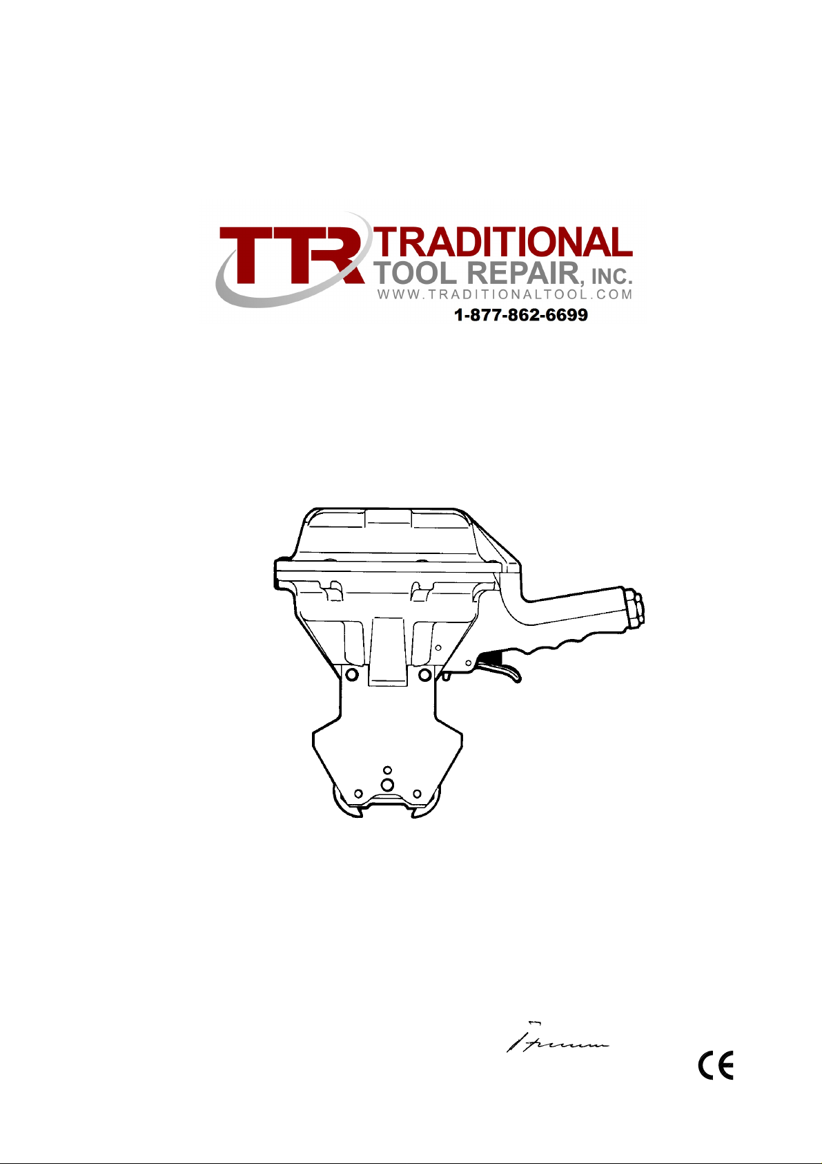
OPERATION MANUAL / SPARE PARTS LIST
PNEUMATIC SEALER
MODEL A461.0002
13.4510.01 - 13.4511.01
CE Declaration of conformity
We declare that the machine A461
is in conformity with the following standard or
13451001.en/MAS/© 02.04
13451101.en
standardised documents:
98/37/EEC
FROMM Holding AG
Hinterbergstrasse 26
CH - 6330 Cham
25.02 2004
R.Fromm
Director
Sales and Service 877-862-6699

INDEX PAGE
1 SAFETY INSTRUCTIONS 3
2 WARRANTY CONDITIONS AND LIABILITY 4
3APPROPRIATE USE 4
4 CHART OF TYPES A461.0002 4
5 TECNICAL DATA 5
5.1 Dimensions . . . . . . . . . . . . . . . . . . . . . . . . . . . . . . . . . . . . . . . . . . . . . . . . 5
5.2 Compressed air. . . . . . . . . . . . . . . . . . . . . . . . . . . . . . . . . . . . . . . . . . . . . 5
5.3 Steel strap. . . . . . . . . . . . . . . . . . . . . . . . . . . . . . . . . . . . . . . . . . . . . . . . . 5
5.4 Seals . . . . . . . . . . . . . . . . . . . . . . . . . . . . . . . . . . . . . . . . . . . . . . . . . . . . . 5
5.5 Joint. . . . . . . . . . . . . . . . . . . . . . . . . . . . . . . . . . . . . . . . . . . . . . . . . . . . . . 5
5.6 Sound information. . . . . . . . . . . . . . . . . . . . . . . . . . . . . . . . . . . . . . . . . . . 6
5.7 Vibration information . . . . . . . . . . . . . . . . . . . . . . . . . . . . . . . . . . . . . . . . . 6
6 INSTALLATION 6
6.1 Compressed air connection. . . . . . . . . . . . . . . . . . . . . . . . . . . . . . . . . . . . 6
6.2 Suspension of tool. . . . . . . . . . . . . . . . . . . . . . . . . . . . . . . . . . . . . . . . . . . 6
7 MAINTENANCE 6
7.1 Air-unit. . . . . . . . . . . . . . . . . . . . . . . . . . . . . . . . . . . . . . . . . . . . . . . . . . . . 6
7.2 Lubrication. . . . . . . . . . . . . . . . . . . . . . . . . . . . . . . . . . . . . . . . . . . . . . . . . 6
8USE 7
8.1 Feeding the strap . . . . . . . . . . . . . . . . . . . . . . . . . . . . . . . . . . . . . . . . . . . 7
8.2 Tensioning the strap . . . . . . . . . . . . . . . . . . . . . . . . . . . . . . . . . . . . . . . . . 7
8.3 Sealing the strap . . . . . . . . . . . . . . . . . . . . . . . . . . . . . . . . . . . . . . . . . . . . 7
9 SPARE PARTS LIST 13. 4510.01/13.4511.01 9
10 JOINT CONTROL 10
11 EXCHANGE OF WEARING PARTS 10
11.1 Exchange of cutting jaws and notching knives . . . . . . . . . . . . . . . . . . . . 10
12 ACCESSORIES 11
WWW.TRADITIONALTOOL.COM
2
Sales and Service 877-862-6699
1 SAFETY INSTRUCTIONS
Read these instructions carefully. Failure to follow these instructions can result in severe personal injury.
Eye injury hazard
Failure to wear safety glasses with side shields can result in
severe eye injury or blindness. Always wear sa fety glasses with
side shields which conform to ANSI Standard Z87.1.
Operation
Tool must not be used by persons not properly trained in their use.
Before tensioning strap, read and understand the tool oper ating
instructions. Failure to follow the operating instructions or improper
load positioning could result in strap breakage.
Become familiar with your tool and keep fingers away from areas
that can pinch or cut.
Joints
You are fully responsible to review the joints made by your tool.
Become familiar with the seal control and seal adjustment
described in this operation manual. Misformed joints may not
secure the load and could cause serious injury. Never handle or
ship any load with improperly formed joints.
Strap breakage hazard
Improper operation of the tool, excessive tensioning, using strap
not recommended for this tool or sharp corners on the load can
result in a sudden loss of strap tension or in strap breakage during
tensioning, which could result in the following:
• A sudden loss of balance causing you to fall.
• Both tool and strap flying violently towards your face.
Note as follows:
• If the load corners are sharp, use edge protectors.
• Place the strap correctly around a properly positioned
load.
• Positioning yourself in-line with the strap, during
tensioning and sealing, can result in severe personal
injury from flying strap or tool. When tensioning or sealing,
position yourself to one side of the strap and keep all
bystanders away.
• Use the correct strap quality, strap width, strap gauge and
strap tensile strength recommended in this manual for
your tool. Using strap not recommended for this tool can
result in strap breakage during tensioning.
•
Cutting tensioned strap
When cutting strapping, use the proper strapping cutter and keep
other personnel and yourself at a safe distance from the strap.
Always stand to side of the strap, away from the direction the
loosened strap end will fly. Use only cutters designed for strap and
never hammers, pliers, hacksaws, axes, etc.
Dispensing strap
Only dispense strap from a dispenser specifically designed for
strap.
Tuck strap end back into dispenser when not in use.
Protective gloves
When handling strap, always wear protective gloves.
Fall hazard
Keep your working area tidy. Untidiness of your working area may
cause a risk of injury. Maintaining improper footing and/or balance
when operating the tool can cause you to fall. Before tensioning
and especially in elevated areas, always establish good balance.
Both feet should be securely placed on a flat, solid surface,
especially when working in elevated areas. Do not use the tool
when you are in an awkward position.
Pay attention to the rules and regulations for preventions of
accident which are valid for the work place.
Tool hazards
A well maintained tool is a safe tool!
Check tool regularly for broken or worn parts. Do not operate a
tool with broken or worn parts.
Never modify any tool. Modification can result in severe bodily
injury.
Strap warnings
Never use strap as a means of pulling or lifting loads. Failure to
follow these warnings can result in severe personal injury.
WWW.TRADITIONALTOOL.COM
Sales and Service 877-862-6699
3
2 WARRANTY CONDITIONS AND LIABILITY
FROMM Holding AG warrants all its strapping tools and machine heads during a period of 90 days from the
date of
Damage claims as a result of production shutdowns and claims for damage to persons and to property resulting
from warranty deficiencies cannot be asserted by the customer.
The warranty excludes:
• wearing parts
• deficiencies resulting from improper installing, incorrect handling and maintaining the tool
• deficiencies resulting from using the tool without or with defective security- and safety devices
• disregard of directions in the operation manual
• arbitrary modifications of the tool
• deficient control of wearing parts
• deficient repair works of the tool
• Use of consumable products not recommended by FROMM Holding AG
We reserve the right to modify the product at any time in order to improve its quality.
sale. The warranty includes all deficiencies clearly resulting from poor manufacturing or faulty materials.
3 APPROPRIATE USE
The tool model A461 has been designed to strap packages with steel strapping exclusively.
The warranty / liability excludes:
• non appropriate use of the tool,
• disregard of directions in the operation manual,
• disregard of control- and mainten anc e ins truc tions.
4 CHART OF TYPES A461.0002
Item No. Model Strap width Strap thickness
Uniflex Ultraflex
13.4310 A461/19/0.63-0.70/N 19mm / 3/4" 0.63-0.70mm / .025"-.028" 0.63-0.70mm / .025"-.028"
13.4311 A461/19/0.63-0.70/P 19mm / 3/4" 0.63-0.70mm / .025"-.028" 0.63-0.70mm / .025"-.028"
13.4312 A461/19/0.8-1.00/N 19mm / 3/4" 0.80-1.00mm / .031"-.040" 0.80-1.0mm / .031"-.040"
13.4313 A461/19/0.80-1.00/P 19mm / 3/4" 0.80-1.00mm / .031"-.040" 0.80-1.0mm / .031"-.040"
13.4410 A461/25/0.80-1.00UNI/
0.80-0.90ULT/N
13.4411 A461/25/0.80-1.00UNI/
0.80-0.90ULT/P
13.4510 A461/32/0.80-0.90/N 32mm / 1 1/4" 0.80-0.90mm / .031"-.035" 0.80-0.90mm / .031"-.035"
13.4511 A461/32/0.80-0.90/P 32mm / 1 1/4" 0.80-0.90mm / .031"-.035" 0.80-0.90mm / .031"-.035"
13.4512 A461/32/1.00UNI/N 32mm / 1 1/4" 1.00m m / .040" --
13.4513 A461/32/1.00UNI/P 32mm / 1 1/4" 1.00mm / .040" --
UNI = Uniflex (Regular Duty max. 850 N/mm2 / 123‘000 psi)
ULT = Ultraflex (High Tensile max. 1100 N/mm
25mm / 1" 0.80-1.00mm / .031"-.040" 0.80-0.90mm / .031"-.035"
25mm / 1" 0.80-1.00mm / .031"-.040" 0.80-0.90mm / .031"-.035"
2
/ 160‘000 psi)
WWW.TRADITIONALTOOL.COM
4
Sales and Service 877-862-6699
A4610002en.teil1

5 TECNICAL DATA
5.1 Dimensions
Assembling "N"
Assembling "P"
Weight net: 4.2 kg / 9.3 lbs
5.2 Compressed air
Joining thread: G 1/4" or G 3/8"
Tube: Min. inside diam. = 8 mm / 5/16"
Max. air pressure: 6 bar / 87 psi
Air consumption: 7.25 Nl / 0.26 cu.ft./seal
5.3 Steel strap
Width: 19 - 32 mm / 3/4" - 1 1/4"
Thickness: 0.63 - 1.0 mm / .025" - .040" maximal
Tensile strength:
Finish: Waxed, smooth edges
600 - 1100 N/mm
2
/ 87 000 - 160 000 psi
5.4 Seals
Strap width: Seal dimensions:
19mm 19 x 45 x 0.9 mm / 3/4" x 1/ 3/4" x .035", with overlapping flanges
25mm 25 x 45 x 0.9 mm / 1" x 1/ 3/4" x .035", with overlapping flanges
32mm 32 x 45 x 0.9 mm / 1 1/4" x 1/ 3/4" x .035", with overlapping flanges
5.5 Joint
Joint strength: approx. 75% of the strap’s tensile strength
WWW.TRADITIONALTOOL.COM
A double notch (two pairs of cut notches) is made per cycle.
A4610002en.teil1
Sales and Service 877-862-6699
5

5.6 Sound information
The A-weighted equivalent continuous sound level at the work place of the machine operator is
typical 84 dB (A).
This value was determined according to DIN 45 635 T3 (11.85).
5.7 Vibration information
The weighted effective value of the acceleration typically amounts to less than 2,5m/s2.
This value was determined according to DIN EN 28 662 T1 (01.93).
6 INSTALLATION
6.1 Compressed air connection
The compressed air is connected to the reducing coupling N6.5133 using a coupling. An air-unit consisting of
a separator for water and dirt, a pressure regulator with a manometer and a lubricator should be installed
within a distance of 15 ft/5 meters. The compressed air must be free from dirt, rust and moisture.
6.2 Suspension of tool
It is possible to suspend the tool on a spring loaded balancer using various suspension brackets.
They have to be ordered separately (see paragraph "ACCESSORIES").
7 MAINTENANCE
Depending on the working conditions and the use of the tool the following maintenance has to be made
periodically:
7.1 Air-unit
• Checking the air-pressure daily (never exceed 87 psi / 6,0 bar).
• Checking oil-level dail y.
• Checking the water separator daily (unless automatic), draining when necessary.
• Cleaning the filter following the instructions of the manufacturer of the air-unit.
Oil for the air unit
HL or CL ISO-VG 10
7.2 Lubrication
When being exchanged, all valve parts and other movable parts have to be greased with grease of type
ESSO BEACON 2 or with some equivalent product.
WWW.TRADITIONALTOOL.COM
6
Sales and Service 877-862-6699
A4610002en.teil1

8USE
8.1 Feeding the strap
The strap is fed through the seal, around the package
to be strapped and pushed again through the seal.
Then the strap end is bent.
Afterwards the operator tensions the loose hoop
manually making sure that the bent strap end is
adjacent to the object to be strapped.
Always wear safety
glasses with side shields
which confor m to ANSI
Standard Z87.1.
When handling strap,
always wear protective
gloves.
8.2 Tensioning the strap
The strap is tensioned with a suitable tensioner
(e. g. Fromm model A451).
8.3 Sealing the strap
Place the sealer on top centre of the seal.
Notch the seal with the strap by pushing the valve
lever until it stops.
It is possible to release the valve lever immediately
after pushing because of the tools automatic sealing
cycle.
Remove the sealer after finishing sealing cycle.
WWW.TRADITIONALTOOL.COM
A4610002en.teil1
Sales and Service 877-862-6699
7
B
C
A46.2125
N6.6123
1 2 3 4A
A46.0108
A46.2128
N6.6204
N2.5180
A46.2150
A46.2151
N6.6208
A46.2146
N1.1815
N2.4902
N41.9128 N4.9159
N41.9129
N2.4902
N1.1815
N1.2114
A46.2152
N2.5198
N4.9136
D
E
F
N6.6213
A46.2130
N6.5133
A46.2127
N6.6235
A46.2129
A48.1237
N1.2108
A46.2154
A46.2126
N1.5305
A46.2143
N6.6204
N6.6232
N1.1808
A46.2147
A46.2149
N2.2164
A46.2116
A46.2148
A46.2121
A46.2118
A46.2145
A46.2109
A46.2145
A46.2113
A46.2132
N2.2118
A46.2134
A46.2153
A46.2118
N2.2124
A46.2145
A46.2116
A46.2117
A46.2154
A46.2143
N1.1118
N1.2108
Loctite 222
Loctite 603
Talcum
ESSO Beacon 2
8
A46.0105
WWW.TRADITIONALTOOL.COM
13451001.z
Sales and Service 877-862-6699

9 SPARE PARTS LIST 13.4510.01/13.4511.01
13.4510.01
13.4511.01 Item-No. Pcs. Description Dimension Field
[A46.0105] 1 JAW ASSEMBLY F2
[A46.0108] 1 CYLINDER BOTTOM C1
A46.2109
A46.2113 ->[A46.0105] 1 DISTANCE SUPPORT E3
A46.2116
A46.2117 ->[A46.0105] 2 JAW PIN F4
A46.2118 ->[A46.0105] 4 FRONT TOGGLE LINK D2+
A46.2121 ->[A46.0105] 1 ROD BAR BOLT D2
A46.2125 ->[A46.0108] 1 VALVE STEM C1
A46.2126 ->[A46.0108] 1 VAL VE SHELL D1
A46.2127 ->[A46.0108] 1 EXHAUST RING C1
A46.2128 ->[A46.0108] 1 SUSTAINING RING C1
A46.2129 ->[A46.0108] 1 SUPPORTING TUBE D1
A46.2130 ->[A46.0108] 1 CONNECTING SCREW D1
A46.2132 ->[A46.0108] 1 LEVER SHAFT D3
A46.2134 ->[A46.0105] 1 BUFFER E3
A46.2143 ->[A46.0105] 2 SIDE PLATE D4+
A46.2145 ->[A46.0105] 4 LEVER BOLT D2+
A46.2146 ->[A46.0108] 1 CYLINDER BOTTOM C2
A46.2147 ->[A46.0108] 1 VAL VE LEVER D2
A46.2148 ->[A46.0108] 1 PIVOTED LEVER D2
A46.2149 ->[A46.0108] 1 SLIDING ROLLER D2
A46.2150 1 CYLINDER COVER A2
A46.2151 1 DIAPHRAGM B2
A46.2152 1 PISTON PLATE B3
A46.2153 ->[A46.0105] 1 PISTON ROD D3
[A46.2154] 2 SAFETY GUARD D4+
A48.1237 ->[A46.0108] 1 SIEVE D1
N1.1118 2 SCREW M8 X 50 E4
N1.1808 ->[A46.0108] 1 SCREW M4 X 10 C2
N1.1815 7 SCREW M6 X 25 A2+
N1.2108 ->[A46.0105] 2 SOCKET COUNTERSUNK HEAD SCREW M6 X 16 D1+
N1.2114 1 SOCKET COUNTERSUNK HEAD SCREW M10 X 40 B3
N1.5305 2 RETAINING NUT M8 D1
N2.2118 ->[A46.0108] 1 PARALLEL PIN 4 M6 X 14 D3
N2.2124 ->[A46.0108] 1 PARALLEL PIN 4 M6 X 40 C3
N2.2164 ->[A46.0105] 1 PARALLEL PIN 6 M6 X 40 E2
N2.4902 4 HAMMER HEAD BOLT 1,85 X 4,76 A3+
N2.5180 ->[A46.0108] 1 PRESSURE SPRING 0.8X7.8X30/8.5 C2
N2.5198 1 PRESSURE SPRING 4,5X67,5X180/7,5 B3
N4.9136 1 LABEL <<A461>> C3
N4.9159 1 LABEL <<CE>> A2
N41.9128 1 ADHESIVE LABEL A3
N41.9129 1 ADHESIVE LABEL A3
N6.5133 ->[A46.0108] 1 REDUCING COUPLING D1
N6.6123 ->[A46.0108] 2 SEAL 12 X 19 X 2.3 C1
N6.6204 ->[A46.0108] 2 O-RING 18 X 2 C2+
N6.6208 1 O-RING 14 X 2 C2
N6.6213 ->[A46.0108] 1 O-RING 20 X 2 D1
N6.6232 ->[A46.0108] 1 O-RING 8 X 2 D2
WWW.TRADITIONALTOOL.COM
N6.6235 ->[A46.0108] 2 O-RING 12 X 2 D1
A461/32/0.80-0.90/N
A461/32/0.80-0.90/P
*
->[A46.0105] 4 NOTCHING KNIFE E3
*
->[A46.0105] 4 CUTTING JAW E2+
A461.0002.01 15/06/98
[ ] = Group * = Wearing Parts
Sales and Service 877-862-6699
913451001.een

10 JOINT CONTROL
A regular control of the joint is necessary. The joint can be checked visually and the person controlling can
easily judge the quality of the joint. Following illustration shows a proper joint:
Sharp edged or misformed joints which do not appear as shown have to be taken away from the load
immediately. The tensile strength of these joints is insufficient and they could cause serious injury.
Having faulty joints proceed as follows:
• Checking the sealing cycle for improper use.(see 8. USE)
• Havin g faulty joints in spit e of proper use inspect th e tool for worn or damaged parts. In case of
wearing out or damaging replace tool parts as needed.
1 1 EXCHANGE OF WEARING PARTS
1 1.1 Exchange of cutting jaws and notching knives
Procedure:
• Unscrew cylinder cover A46.2150 (7 recessed countersunk head screws).
• Remove diaphragm A46.2151.
• Unsc rew pisto n plate A46 .2152 (scr ew N1.2114), push piston plate a gainst the pr essure sp ring at
the same time.
• Remove pressure spring.
• Disas s emb le sc rews N1.1118 and remove jaw assembly.
• In order to be able to exchange notching knives and cutting jaws the side plates have to be
removed from the jaw assembly. For this remove screws N1.2108.
• Assembling in opposite order.
Important!
WWW.TRADITIONALTOOL.COM
10
Safe screw N1.2114 with Loctite 222.
A4610002en.teil2
Sales and Service 877-862-6699

12 ACCESSORIES
Following suspension brackets can be mounted on the tool and have to be ordered separately:
Suspensions for tool assembling „N“
Universal suspension
A46.2201
for normal, vertical and
horizontal working position
Suspensions for tool assembling „P“
Universal suspension
A46.2207
for normal, vertical and
horizontal working position
Suspension
A46.2210
left side
Suspension
A46.2213
left side
Suspension
A46.2216
right side
Suspension
A46.2218
right side
WWW.TRADITIONALTOOL.COM
A4610002en.teil2
Sales and Service 877-862-6699
11

WWW.TRADITIONALTOOL.COM
12
Sales and Service 877-862-6699
A4610002en.teil2
 Loading...