

Page 1
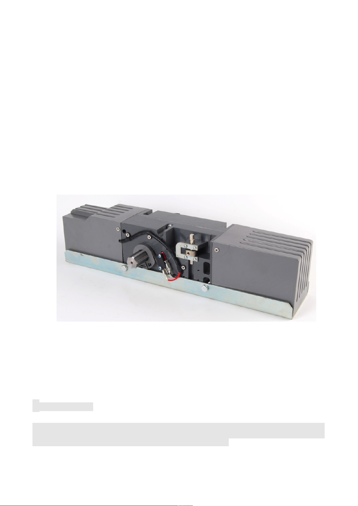
TILT
ORIGINAL OPERATING INSTRUCTIONS
DEAR CUSTOMER,
Thank you for purchasing this product. Please read all the instructions in this manual
carefully, before you assemble or use the product. Should you pass on this product to third
parties, please hand over the instruction manual along with it.
Page 2

1. IMPORTANT SAFETY INFORMATION
Make sure the power supply (AC110V or AC220V) of the gate operator is
suitable for the power supply of the electrical outlet you are using.
Do not allow children to play with fixed controls. Keep remote controls away from
children.
Remote control is single button control; it means that one button control ON,
STOP, OFF mold, when press button for each mold, the indicator lighted. In
addtion to the remote control operating mold, manually free the key can be used to
liberating the motor and door, the door can be runned manually, pull down the
relief handle 90 degrees into horizontal position for relief, relief the handle and
closed for locking. See the instructions 9.
When operating a biased-off switch, make sure that other persons are kept away.
Frequently examine the installation for imbalance and signs of wear or damage to
cables, springs and mounting. Do not use if repair or adjustment is necessary.
This equipment is not suit for persons with reduced physical or sensory, mental
capabilities, lack of experience or knowledge (including children). Unless they
have been given supervision by a professional person.
Repairs may only be carried out by professionals with the appropriate knowledge
about the device.
Page 3

Page 4
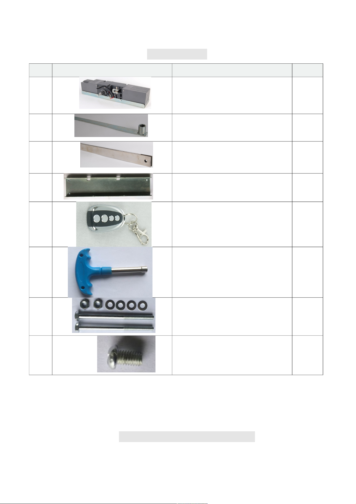
2. PART LIST
3. TECHNICAL INFORMATION
No. Image Description Qty.
1 Gate Operator 1x
2
3 Sliding rod 1x
4 Remote Control 2x
5 Key (for Manual Operation) 1x
Rod 1x
Mounting base plate 1x
6 Nut (M8) for Gate Operator 2x
7 Retainer bolt M6X10 1x
Page 5
Type TILT
Power supply 230V, 50Hz
Rated output power of motor 200W
Output torque 350N·m
Speed 1.75rpm
Door max. surface 9
㎡
Remote control operating distance 30m (Frequency:433.92mHz)
Remote control mode Single button
Limit switch Spring limit switch
Noise ≤58dB
Duty cycle S2, 15 minutes
Extra remote control 20
Environmental temperature -20°C ~ +70°C
4. INSTALLATION
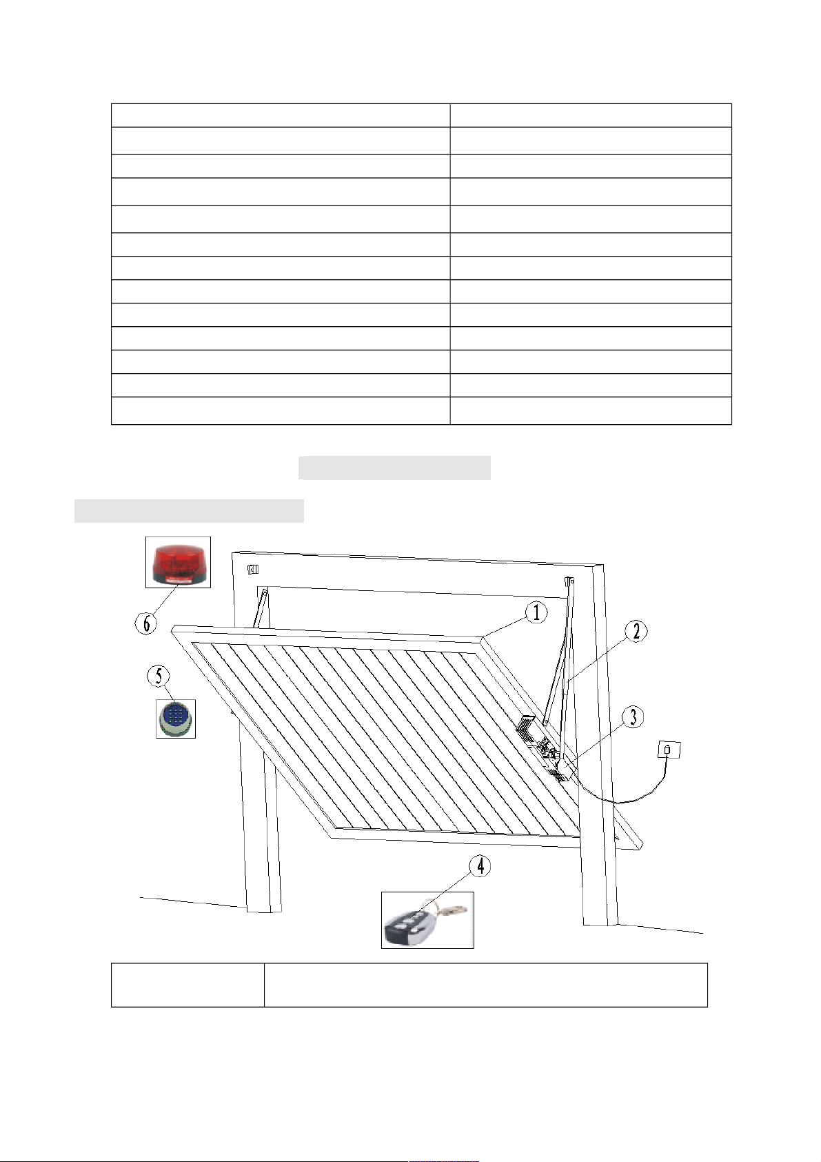
4.1 Installation diagram
1 Door
Page 6
2 Rod & sliding rod
3 TILT motor
4 Remote control
5 Wireless keypad (optional)
6 Alarm lamp (optional)
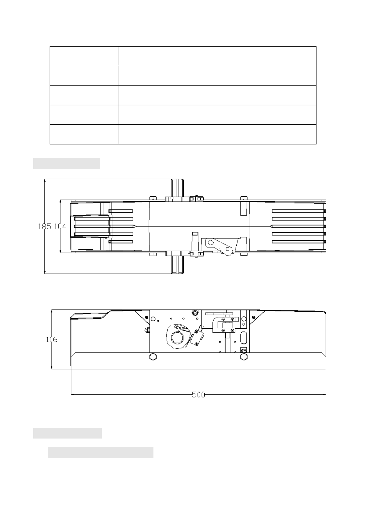
4.2 Dimension
4.3 Installation
A、Overall flip up type
Page 7
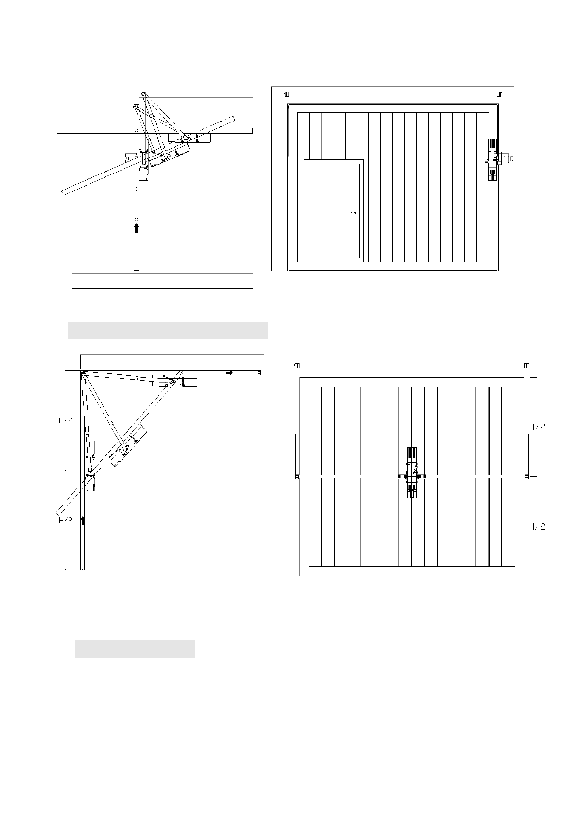
B、Overall slide down type
C、Folding type
Page 8
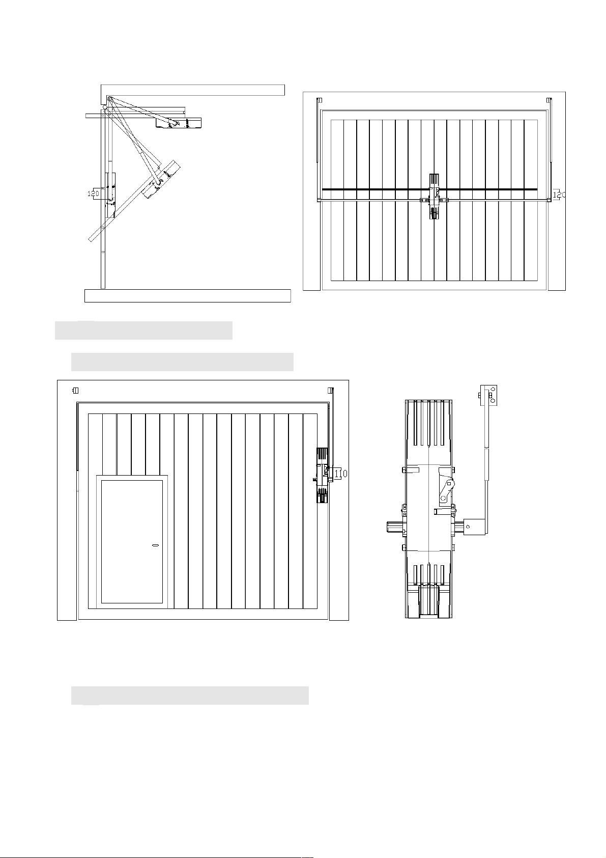
4.4、Installation of link
A、Unilateral single rod type
B、Unilateral double rods type
Page 9
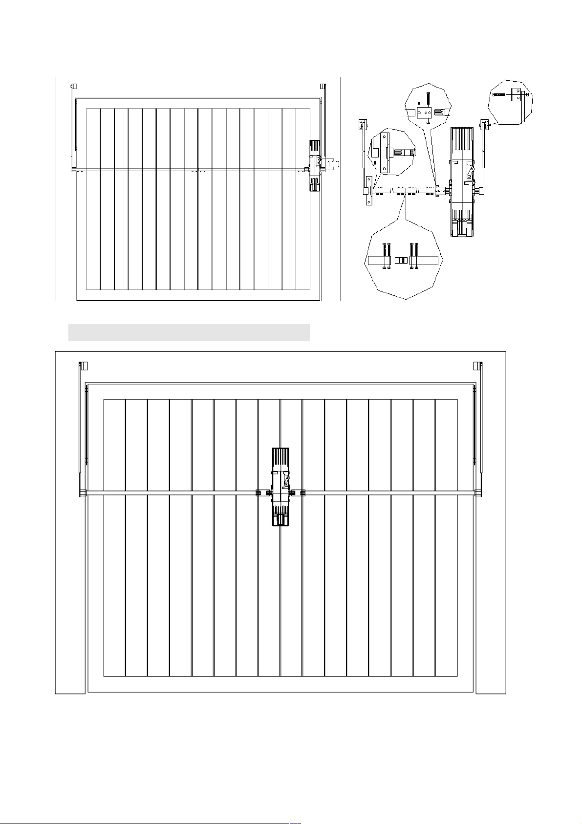
C、Intermediate double rod type
Page 10
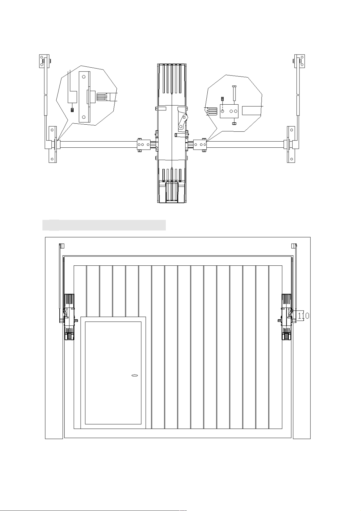
D、Installation of two motors
Page 11
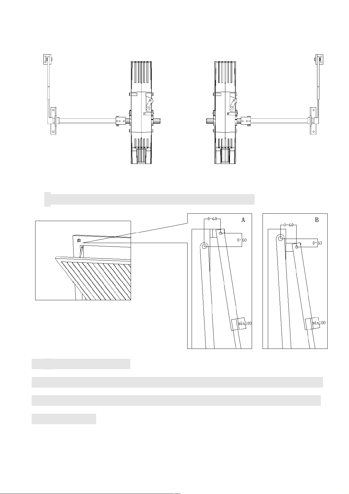
*
The relative mounting size of the rod and link
4.5
、
Manual operation
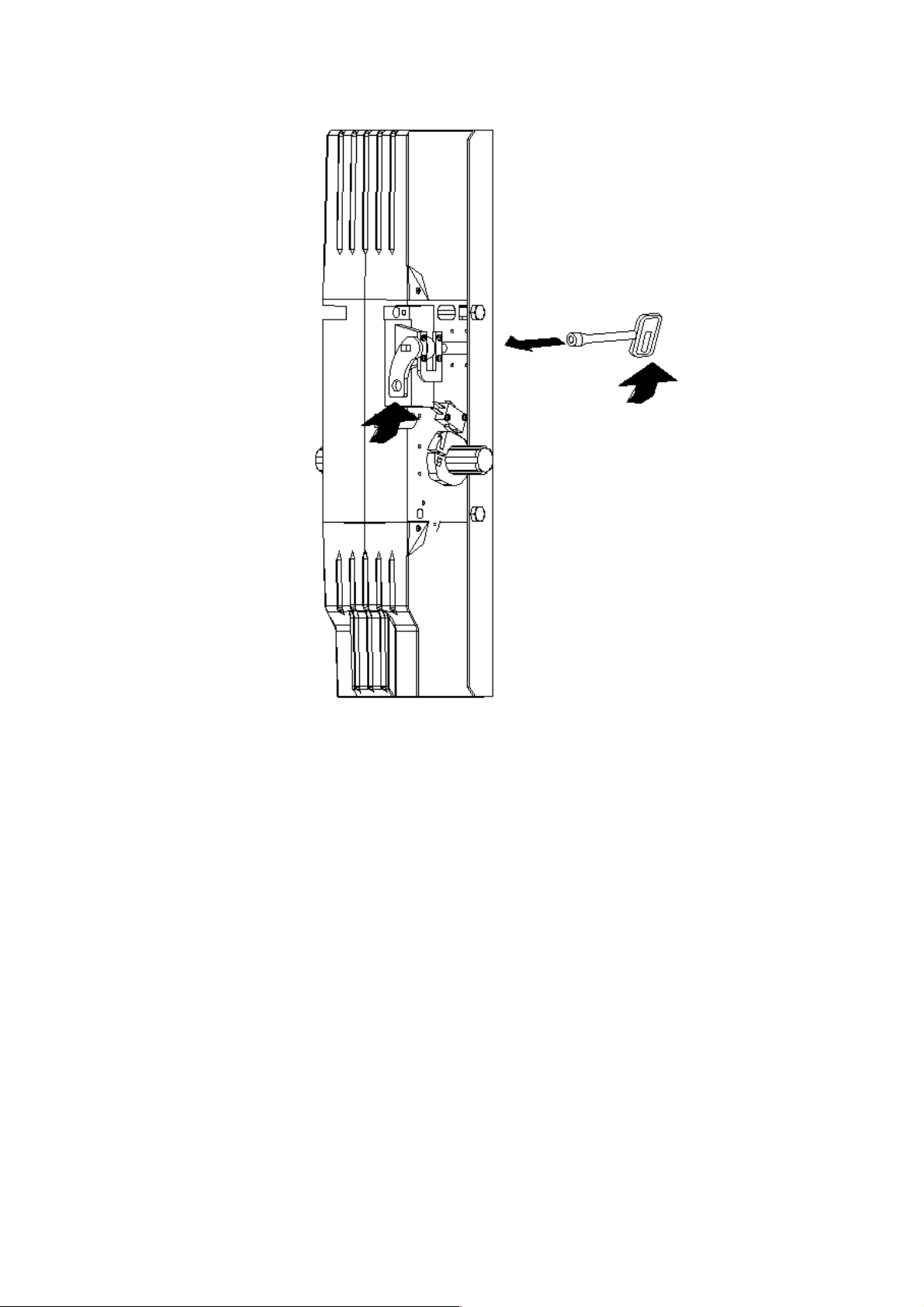
In case of power failure, fit the supplied key in the unlock rod (as
shown below), turn it clockwise 180°, then can open or close the
gate manually.
Page 12
Page 13
5. WIRE CONNECTION
Fig.1
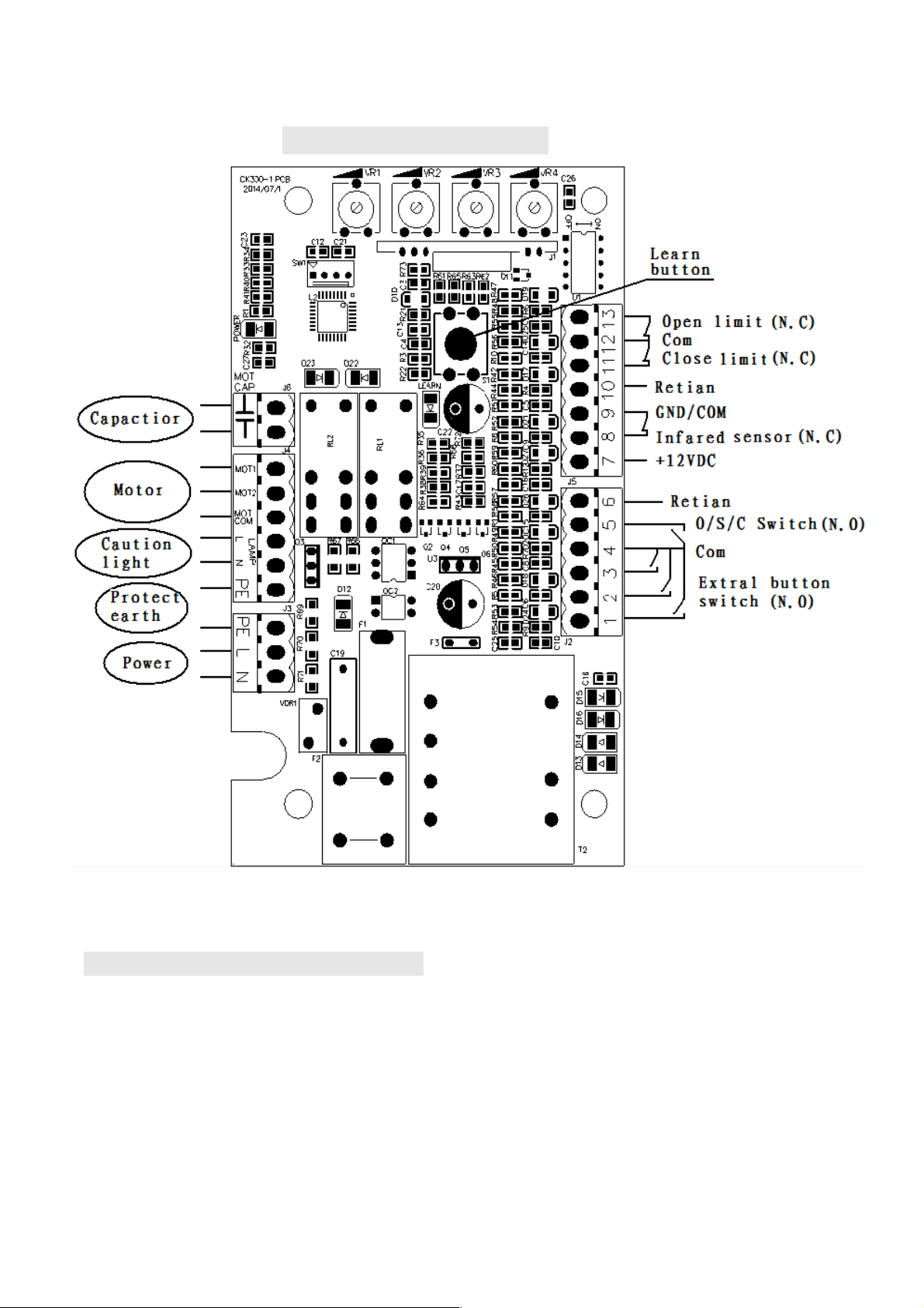
5.1 Wiring notes of control board
a.
Power Input (terminal J3): PE (Earth),L (Live),N (Neutral).
b. Caution light: connect caution light wire to L and N of LAMP(terminal J4)
c. Limit switch: Open limit(13 of J5) ,Com(12 of J5) ,Close limit(11 of J5)
Page 14
d.
Three-button mode external button switch:Open(2 of J2),Close(1 of J2),Stop
(3 of J2),Com(4 of J2)
e.
Single-button mode external button switch: Single-button(5 of J2),Com(4 of J2)
f.
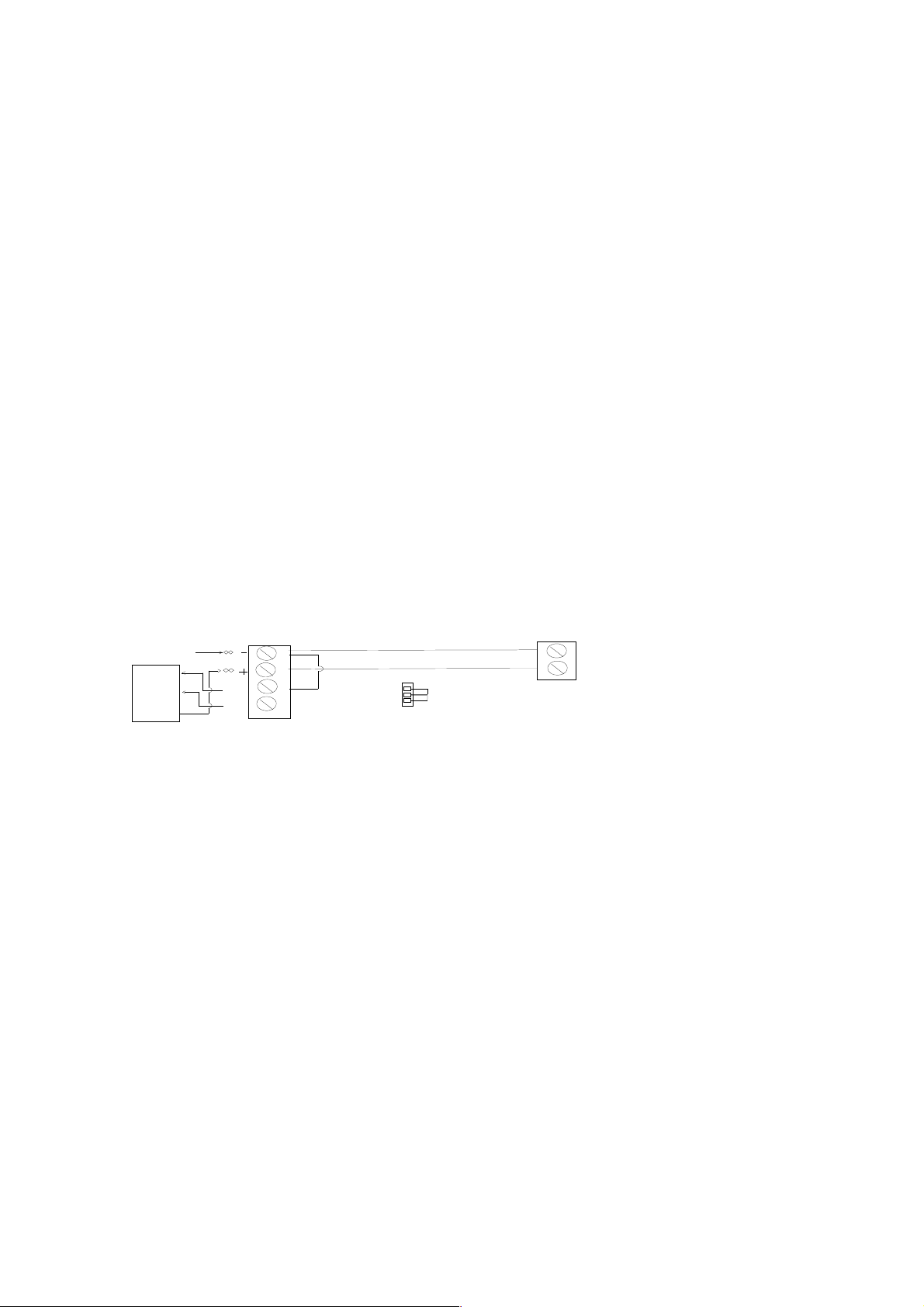
Output power supply: 12VDC(7 of J5), COM (9 of J5), I.R. (8 of J5 is N.C
Infrared)
If the infrared beam is interrupted during closing, the gate will reverse and open
immediately. The product is not factory equipped with an infrared device; the
infrared out put signal must be N.C.
From four-terminal
to the receiver
COM
OUT
RX Receiver connecting
JUMP
NC OR NO
NC
NO
Form two-terminal to the emitter
12--24V AC/ DC
TX Emitter connecting
power supply
7
9
8
Control board
Terminal J5
Fig.2 infrared Schematic diagram
g.
Three-button switch / single-button switch (keypad): The TILT is equipped with
interfaces for three-button switch and single-button switch (keypad).
To install the keypad attach one lead of your keypad to ‘5’ of terminal J2 and the
other to the ‘4(COM)’. The keypad will function in single channel mode.
h.
For three-button switch installation, use the terminals for multi-channel mode.
Connect open wire of external button switch to ‘1 (OPEN)’ of terminal J2,
Page 15
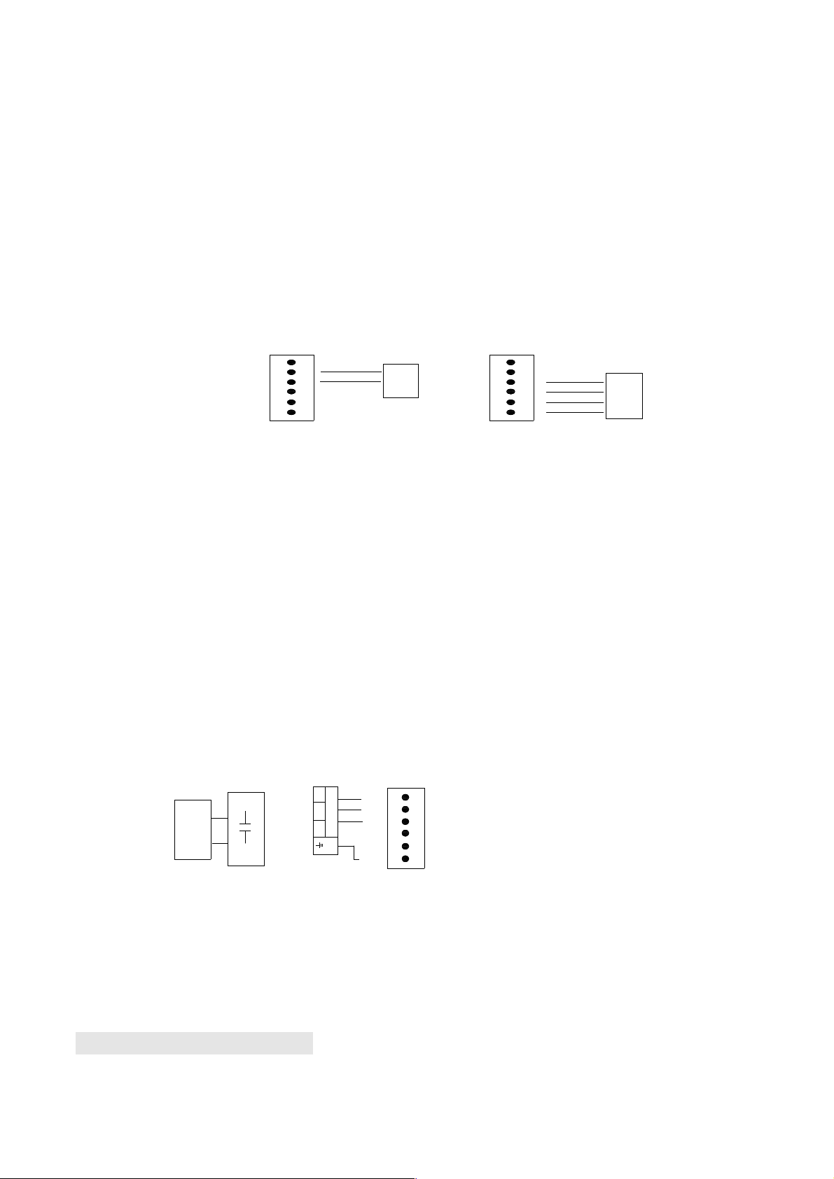
connect close wire of switch to ‘2 (CLOSE)’, connect stop wire of switch to
‘3(STOP)’, connect common wire of switch to ‘4(COM)’.
Com
Stop
Close
Open
Three-button
switch
terminal J2
Keypad
4
5
Control board
terminal block
Control board
terminal block
Single-button
switch
or keypad
6
1
2
3
terminal J2
4
5
6
1
2
3
Fig.3
i.
Motor and capacitor (Terminal J2, J4): MOT COM (com), MOT1 (Positive
direction), MOT2 (Opposite direction), PE (Protect Earth), C and C (capacitor)
Motor
Mot1
Mot2
Mot
COM
PE
W
U
V
Control
board
Terminal J6
Capacitor
Control board
terminal block
terminal J4
Fig.4
5.2. Tuning and operation
Page 16

a. Adjust the Adjustable resistance (see Fig.1)
VR1: For slow stop width adjustment after touch the open limit switch.
(Remark: DIP switch “3” at the position “ON”.)
Clockwise rotation to increase, counter-clockwise rotation to reduce.
The total time can be set to 0 seconds as minimum and 5 seconds as maximum.
VR2: For slow stop width adjustment after touch the close limit switch.
(Remark: DIP switch “4” at the position “ON”.)
Clockwise rotation to increase, counter-clockwise rotation to reduce.
The total time can be set to 0 seconds as minimum and 5 seconds as maximum.
VR3:For auto-close time adjustment.
(Remark: DIP switch “1” at the position “ON”.)
Clockwise rotation to increase, counter-clockwise rotation to reduce.
The total time can be set to 0 seconds as minimum and 70 seconds as
maximum.
VR4: For motor working total time adjustment.
Clockwise rotation to increase, counter-clockwise rotation to reduce.
The total time can be set to 10 seconds as minimum and 60 seconds as
maximum.
Warning: Motor force can not be set too large, just drive the door is ok.
Page 17

Remote control
The remote control works in a single channel mode. It has four buttons. See
Fig.12 Remote transmitter. The function of button 1, button 2、 button3 are the
same and button 4 is pedestrian mode. With each press of the remote control
button (1, 2 and 3) which has been programmed, the gate will close, stop, open
or stop cycle.
You can program/learn button 1, button 2, button 3 and button4 individually. If
you learn button1, the button 1 is enable, button 2, button 3 and button4 are
disable. if you learn button 2 too.
Button 1
Button 2
Button 3
Button 4
Fig.5Remote transmitter
Adding extra remote controls (Learn) : Remove the cover, press and hold the
learn button ‘S1’ (Fig.1) more than 1 seconds, then the ‘LED of LEARN’ (Fig.1)
will be on, then press the remote control button which you want to use, the
‘LED’ will turn on about 2 seconds and then turn off again. The learning
process is finished.
Up to 25 remote controls may be used.
Erase remote controls : To erase all existing remote controls, press and hold
Page 18
learn button ‘S1’, the LED of ‘LEARN’ will turns on, release the button until the
LED turns off. This indicates that all the remote controls have been erased
completely. If you change another manufactory code transmitter must erase
first.
Verify open direction: If the gate does not move in the desired direction, then
you will need to reverse the motor operating direction, open the black plastic
cover, you can do this by exchanging wires ‘MOT1’ and ‘MOT2’, ‘Open limit(13
of J5)’ and ‘Close limit(11 of J5)’
.
5.3. Programming Process
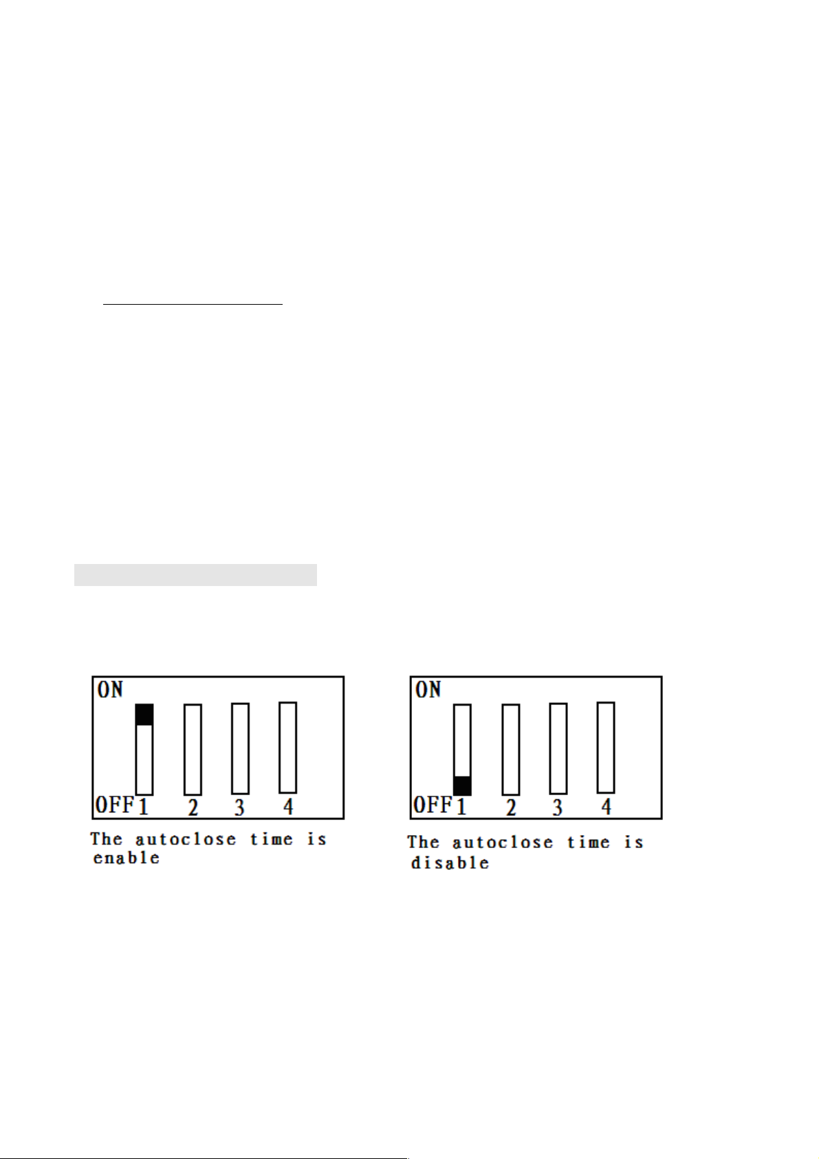
Adjust the DIP switch(see Fig6 and table 1
)
Fig6A
Page 19
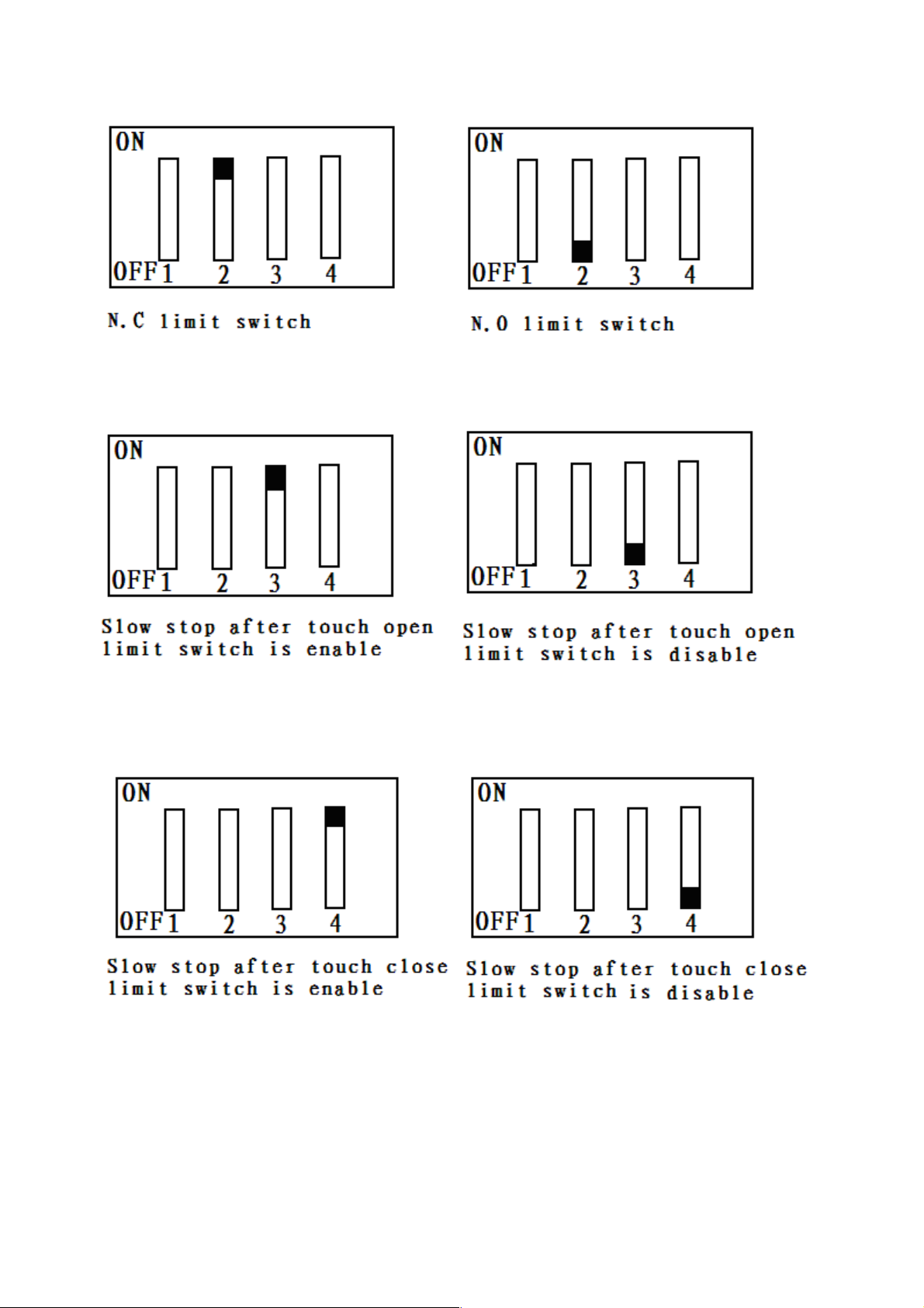
Fig6B
Fig6C
Fig6D
Table 1: DIP switch adjust
Page 20

DIP DIP-switch Function SET
1
ON
the Auto-close function is enable,
Rotate VR3 to adjust the width
OFF
the Auto-close function is disable
2
ON
N.C. limit switch(spring limit)
OFF
N.O. limit switch(spring limit)
3
ON
Slow stop after touch open limit switch is enable
Rotate VR1 to adjust the width
OFF
Slow stop after touch open limit switch is disable
4
ON
Slow stop after touch close limit switch is enable
Rotate VR2 to adjust the width
OFF
Slow stop after touch close limit switch is disable
NOTE:
(1)
You must follow the operating instruction as above, any wrong operation
is not allowed during setting. If your device responds to your requested
function correctly, you have set the function successfully, otherwise
repeat the above setup instruction until your device responds to your
expected function.
(2)
If the gate can not be moved, please check whether the gate is obstructed
or the gate is too weight.
Page 21

Activities Covered in this section
Remote transmitter: With each press of the button, the gate will close, stop,
open or stop cycle. (Single-button mode)
Three-button mode external button switch : press ‘OPEN’ button, the gate
opens. Press ‘STOP’ button, the gate stops. Press ‘CLOSE’ button, the gate
closes.
Single-button mode external button switch / keypad : With each press of
the button, the gate will close, stop, open or stop cycle.
Auto-close function: This feature can be selected to make the gate stay open
for some seconds before it automatically closes. The auto-close time can be
adjusted to between 0 and 70 seconds.
Safe guard (Infrared photocell): If infrared beam is interrupted during closing,
the gate will reverse and go open immediately. This feature will not function if
the gate is in fully opened and closed positions or during opening.
Open priority: The gate will return to open if press ‘OPEN’ button of external
button switch during closing.
Limit switch: The switch is used to accurately stop the gate in the opened and
closed positions.
If the gate stops at opened position when the limit switch is reached, the gate
will not move if you press ‘OPEN’ button.
Page 22

If the gate stops at closed position when the limit switch is reached, the gate
will not move if you press ‘CLOSE’ button.
The device is installed with a thermal protector, the thermal protector will switch
off the motor automatically in case of the temperature is higher than 120°C and
switch on the motor automatically when the temperature is lower than 85°C±5
°C.
6.Maintenance
Check the door once a month. The door should be carefully checked for
balance. The door must be in good working order.
We suggest for safety reasons, photocells be used on all gates.
Disconnect from mains supply before replacing bulb.
Be sure to read the entire manual before attempting to perform any installation
or service to the door operator.
Our company reserves the right to change the design and specification without
prior notification.
Page 23

7.Troubleshooting
Trouble Possible causes Solutions
The door fails to
open and close.
LED display
does not light.
1. Power is OFF
2. Fuse burn
1. Make sure that power is
ON.
2. Replace fuse.
The door can
open fails to
close.
1. Infrared beam is
obstructed.
2. Infrared sensor
function is enabling,
but the sensor has not
been installed.
1. Remove obstructions.
2. Make sure the infrared
sensor function is disabling.
Remote
transmitter does
not work.
1. Battery level may be
low
2. Transmitter code is
lost
1. Replace the battery inside
the transmitter.
2. Reprogram the transmitter.
The transmitter Battery level may be Replace battery.
Page 24

operating
distance is too
short.
low.
 Loading...