

Tradewinds RNC5-TPD, RNC5-TPF Installation Instructions Manual

Package 1 of 1 contains:
1 - Assembled ventilator
1 - Bag assembly containing:
1 - Drain spout assembly (HRV units only)
4 - Hanging straps
1 - Installation manual
Installation Tools
• tin snips • large zip ties
• assorted screw drivers • fabric flexible duct
• electric drill - class II rated
• hammer • mastic tape
• wire strippers • alum. foil duct tape
• knife • zip ties
• caulking gun •
1/2” I.D. drain hose
• smoke pencil
Balancing Tools
•
Pitot Tube Balancing Kit
[Case, 8 ft. vinyl tubing, Pitot tube,
magnehelic gauge (0 - 0.25”), and
mounting plate]
•
Pitot Tube with instructions
and Digital Manometer
(with resolution of
0 - 0.25” - must read to 1/100ths of an inch)
Optional Accessories
•
20 Minute Fan Timer
• Wall Mounted Dehumidistat
•
Weather hood Kit
• Round Diffuser
4” (100mm)
5” (127mm)
6” (150mm)
8” (200mm)
• Kitchen Grille
- may be required by code for kitchen applications
- contains removable grease filter
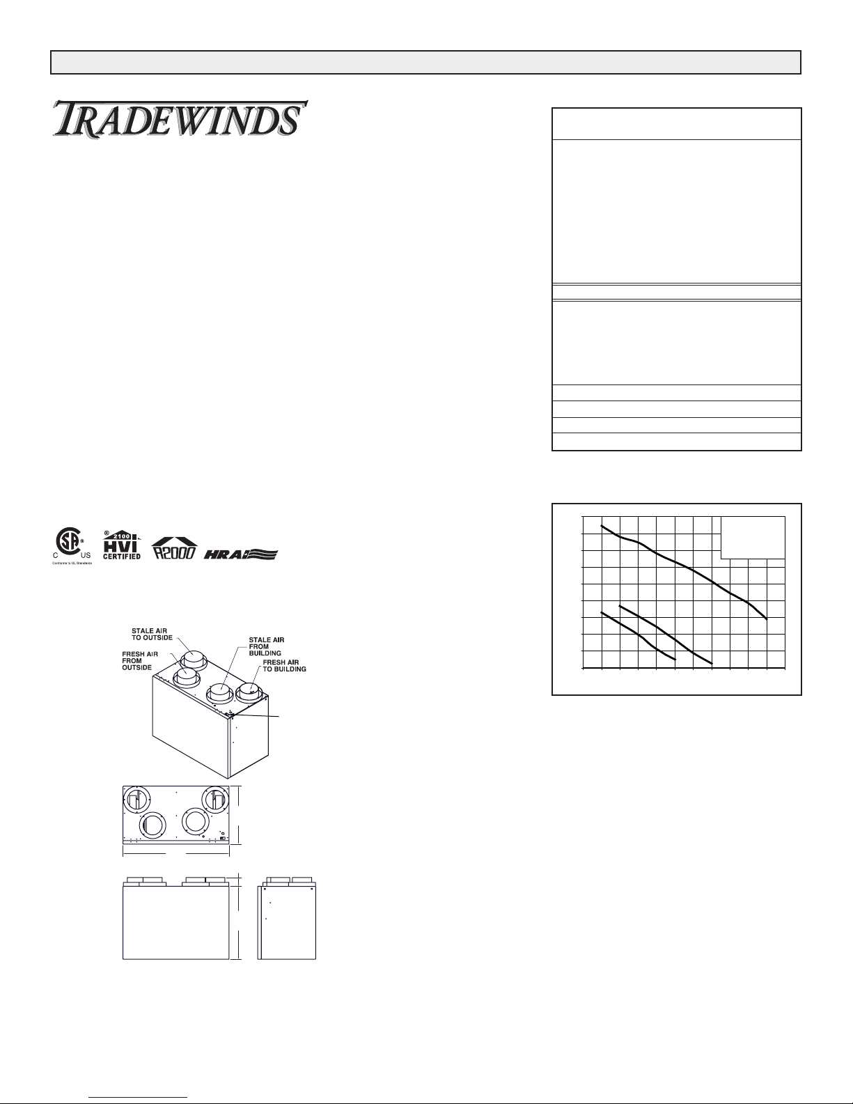
Heat Recovery Ventilators (HRV) are designed to provide fresh air while exhausting an equal amount of stale
air.
The HRV is equipped with an aluminum core. The
device uses the stale air that is being exhausted to condition the fresh air as it is being brought in.
These instructions are intended as a general guide and do
not supersede local codes in any way. Consult authorities
who have jurisdiction before installation.
Shipping and Packaging List......................................................1
Required Tools ...........................................................................1
Application .................................................................................1
General ......................................................................................1
Engineering Data ....................................................................2-3
Clearances & Requirements ......................................................4
Installation...............................................................................4-7
Application Illustrations .........................................................8-10
Electrical .................................................................................11
Remote control devices............................................................12
Wiring the Controls ..................................................................13
Operation .................................................................................14
Changing Speeds ....................................................................14
Fan Speed DIP Switch Settings...............................................14
Wiring Diagrams .................................................................15-16
Interlocking HRV to Furnace....................................................17
Defrost Operation.....................................................................18
Defrost Cycle DIP Switch Settings...........................................18
Dehumidistat Operation ...........................................................18
Airflow Balancing ................................................................19-20
Troubleshooting........................................................................21
Maintenance ...........................................................................22
Shipping and Packing List
Application
General
Table of Contents
Required Tools
* LEAVE FOR HOMEOWNER
NOTE: Due to ongoing research and product development, specifications,
ratings and dimensions are subject to change without notice.
TW-TPD-001
0307
HEAT RECOVERY VENTILATOR
MODELS RNC5-TPD, RNC5-TPF
INSTALLATION INSTRUCTIONS
HEAT RECOVERY VENTILATOR
TM
Date: _______________________________________________
Tag: _____________________Qty: _______________________
Project: _____________________________________________
Engineer: ____________________________________________
Contractor:___________________________________________
Supplier: ____________________________________________
Quote#: _____________________________________________
Submitted by:_________________________________________
2
Engineering Data Model RNC5-TPD
THERMALLY CONDUCTIVE, PATENTED ALUMINUM CORE
The cross-flow heat recovery core transfers heat between the two airstreams.
It is easily removed for cleaning or service.
MOTORS AND BLOWERS
Each Air stream has an independent motorized impeller. 120VAC
FILTERS
Washable air filters in exhaust and supply air streams.
DEFROST
The damper closes off the supply air from outside allowing the exhaust air to
recirculate through the unit.
CASE
Twenty gauge prepainted galvanized steel (G60) for superior corrosion resistance. Insulated to prevent exterior condensation. Drain connections 1/2" (12
mm) OD.
MOUNTING THE HRV
Four threaded inserts at corners of case designed to accept four reinforced
polyester straps that are supplied with the unit.
CONTROLS- HRV System Control
HRV defaults to user selected speed from switch on top of cabinet when
plugged in. HIGH SPEED option is accessible by connecting remote controls
to designated terminals inside electrical box of HRV.
OFF(Standby)/LOW or OFF/HIGH speed operation is also available.
DUCT CONNECTIONS
4 - 5” (127 mm) duct connections.
Weight 61 lbs. (28 kg) Shipping Weight 64 lbs. (29 kg)
All units conform to CSA and UL standards.
HEAT RECOVERY VENTILATOR
Dimensions
OPTIONAL ACCESSORIES
99-101 Crank Timer
99-116 Dehumidistat Ventilation Control - Dehumidistat with ON/OFF
99-130 Dehumidistat Control - Dehumidistat
99-132 20 Minute Fan Timer - (3 wire) 20 gauge wire (min.) 100’ length
(max.)
99-185 Weatherhoods, Two - 5” (125mm) c/w 1/4” (6mm) mesh screen
99-186 Weatherhoods, Two - 6" (150mm) c/w 1/4" (6mm) mesh screen
99-2040 20/40 ON/OFF Dehumidistat
99-RECIRC Recirculation Control
WARRANTY
Units carry a fifteen (15) year warranty on the heat recovery core and a 5
year replacement parts warranty.
*Sensible Efficiency - thermal **Latent Efficiency - moisture
Note: Effectiveness - based on temp. differential between the 2 airstreams
Efficiency - takes into account all power inputs
Performance (H.V.I. certified)
Net supply air flow in cfm (L/s) against external static pressure
E.S.P
(external static pressure) [cfm (L/s)]
@ 0.1" (25 Pa) 169 (80)
@ 0.2" (50 Pa) 156 (73)
@ 0.3" (75 Pa) 149 (70)
@ 0.4" (100 Pa) 136 (64)
@ 0.5" (125 Pa) 126 (59)
@ 0.6" (150 Pa) 116 (54)
@ 0.7" (175 Pa) 103 (48)
@ 0.8" (200 Pa) 89 (42)
@ 0.9" (225 Pa) 77 (36)
@ 1.0" (250 Pa) 58 (27)
Max. Temperature Recovery 78%
Sensible Effectiveness
@ 66 cfm (31 L/s) 32°F (0°C) 74%
*Sensible Efficiency
@ 66 cfm (31 L/s) 32°F (0°C) 61%
*Sensible Efficiency
@ 76 cfm (36 L/s) -13°F (-25°C) 63%
VAC @ 60HZ 120
WATTS / Low speed. 69
WATTS / High speed 147
Amp rating 1.7
TM
HEAT RECOVERY VENTILATOR
180
3
160
140
120
100
80
Air Flow (cfm)
60
40
20
2
1
0
0 0.1 0.2 0.3 0.4 0.5 0 .6 0.7 0.8 0.9 1 1.1
Static Pressure (in w.g.)
3 - High Speed
*2 - Medium Low Speed
*1 - Low speed
* Manufacturers Dat a
SPEED
SELECTION
SWITCH
15”
(378 mm)
27”
(690 mm)
2-1/4”
(57 mm)
18-3/4”
(475 mm)
Date: _______________________________________________
Tag: _____________________Qty: _______________________
Project: _____________________________________________
Engineer: ____________________________________________
Contractor:___________________________________________
Supplier: ____________________________________________
Quote#: _____________________________________________
Submitted by:_________________________________________
3
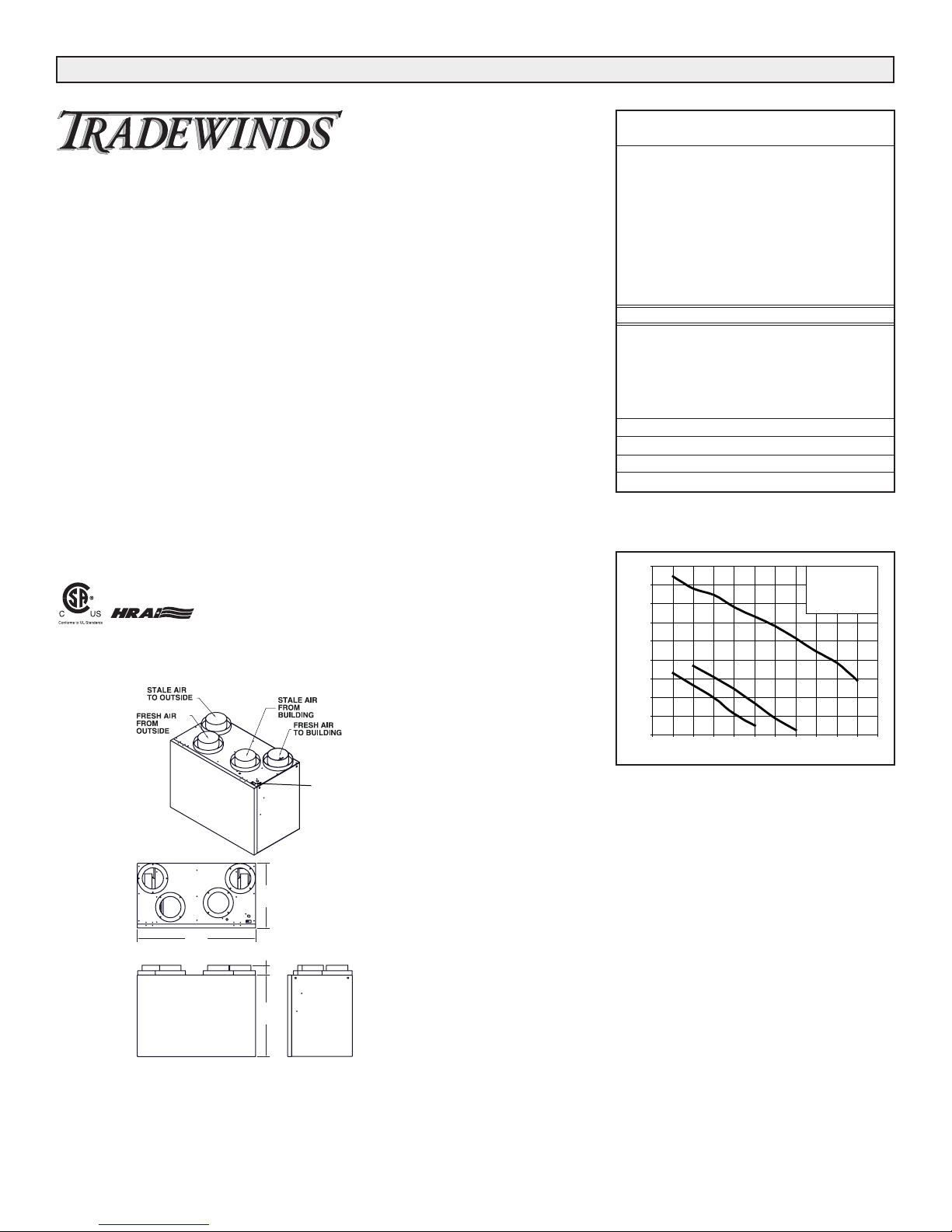
HEAT RECOVERY VENTILATOR
Engineering Data Model RNC5-TPF
THERMALLY CONDUCTIVE, PATENTED ALUMINUM CORE
The cross-flow heat recovery core transfers heat between the two airstreams. It
is easily removed for cleaning or service.
MOTORS AND BLOWERS
Each Air stream has an independent motorized impeller. 120VAC
FILTERS
Washable air filters in exhaust and supply air streams.
DEFROST
Supply air motor switches off and exhaust motor switches to high speed to
defrost core.
CASE
Twenty gauge prepainted galvanized steel (G60) for superior corrosion resistance. Insulated to prevent exterior condensation. Drain connections 1/2" (12
mm) OD.
MOUNTING THE HRV
Four threaded inserts at corners of case designed to accept four reinforced polyester straps that are supplied with the unit.
CONTROLS- HRV System Control
HRV defaults to user selected speed from switch on top of cabinet when
plugged in. HIGH SPEED option is accessible by connecting remote controls to
designated terminals inside electrical box of HRV.
OFF(Standby)/LOW or OFF/HIGH speed operation is also available.
DUCT CONNECTIONS
4 - 5” (127 mm) duct connections
Weight 61 lbs. (28 kg) Shipping Weight 64 lbs. (29 kg)
All units conform to CSA and UL standards.
Dimensions
1
2
3
0
20
40
60
80
100
120
140
160
180
0 0.1 0 .2 0 .3 0.4 0.5 0 .6 0 .7 0.8 0.9 1 1.1
Static Press ure (in w.g.)
Air Flow (c fm)
3 - High Speed
2 - Medium Low Speed
1 - Low speed
*Sensible Efficiency - thermal **Latent Efficiency - moisture
Note: Effectiveness - based on temp. differential between the 2 airstreams
Efficiency - takes into account all power inputs
Performance
Net supply air flow in cfm (L/s) against external static pressure
E.S.P
(external static pressure) [cfm (L/s)]
@ 0.1" (25 Pa) 169 (80)
@ 0.2" (50 Pa) 156 (73)
@ 0.3" (75 Pa) 149 (70)
@ 0.4" (100 Pa) 136 (64)
@ 0.5" (125 Pa) 126 (59)
@ 0.6" (150 Pa) 116 (54)
@ 0.7" (175 Pa) 103 (48)
@ 0.8" (200 Pa) 89 (42)
@ 0.9" (225 Pa) 77 (36)
@ 1.0" (250 Pa) 58 (27)
Max. Temperature Recovery 78%
Sensible Effectiveness
@ 66 cfm (31 L/s) 32°F (0°C) 74%
*Sensible Efficiency
@ 66 cfm (31 L/s) 32°F (0°C) 61%
*Sensible Efficiency
@ 65 cfm (30 L/s) -13°F (-25°C) 50%
VAC @ 60HZ 120
WATTS / Low speed. 69
WATTS / High speed 147
Amp rating 1.7
OPTIONAL ACCESSORIES
99-101 Crank Timer
99-116 Dehumidistat Ventilation Control - Dehumidistat with ON/OFF
99-130 Dehumidistat Control - Dehumidistat
99-132 20 Minute Fan Timer - (3 wire) 20 gauge wire (min.) 100’ length
(max.)
99-185 Weatherhoods, Two - 5” (125mm) c/w 1/4” (6mm) mesh screen
99-186 Weatherhoods, Two - 6" (150mm) c/w 1/4" (6mm) mesh screen
99-2040 20/40 ON/OFF Dehumidistat
WARRANTY
Units carry a fifteen (15) year warranty on the heat recovery core and a 5
year replacement parts warranty.
TM
HEAT RECOVERY VENTILATOR
SPEED
SELECTION
SWITCH
15”
(378 mm)
27”
(690 mm)
2-1/4”
(57 mm)
18-3/4”
(475 mm)
4
Location Selection
The HRV must be located in a heated space where it will
be possible to conveniently service the unit. Typically the
HRV would be located in the mechanical room or an area
close to the outside wall where the weather hoods will be
mounted. If a basement area is not convenient or does not
exist, a utility or laundry room may be used.
Attic installations are not normally recommended due to:
A) the complexity of work to install
B) freezing conditions in the attic
C) difficulty of access for service and cleaning
The HRV unit must be installed in a horizontal position as
shown in the illustration on the next page. The unit should
be suspended using the provided hanging straps. If necessary, the unit may be installed on a platform: however,
the cabinet should be isolated from the platform to prevent
vibration transmission. The unit must be level. Sufficient
clearance at the front of the access door is required for
servicing the air filters and core. A minimum of 25"
(635mm) clearance is recommended so the door can be
opened. Four PVC reinforced polyester hanging straps are
provided for hanging the HRV from the basement floor
joists.
Suspending the Unit
The hanging straps should be attached to the unit at the
top end corners (mounting screws are already located on
the HRV case). Securely fasten the other end of the straps
to the floor joists with wide head nails (not supplied), making sure the UNIT IS LEVEL. The straps are designed to
reduce the possibility of noise, resonance or harmonics;
therefore using the full length of the strap between the
HRV and the floor joists is recommended.
Weatherhood Location and Installation
Weatherhood kit includes two fixed-cover hoods with a 1/4”
(6mm) mesh screen.
Exhaust Weatherhood Requirements
• At least 6' (2 m) from the ventilation air intake*
• At least 18" (460 mm) above ground or above the
depth of expected snow accumulation*
Installation
Connecting Appliances to the HRV
The following appliances should not be connected to the
HRV:
• clothes dryer
• range top
• stovetop fan
• central vacuum system
NOTE: Connecting any of these to the HRV will
invalidate your warranty.
Clearances and Requirements
WARNING
Before installation, careful consideration must
be given to how this system will operate if
connected to any other piece of mechanical
equipment, i.e. a forced air furnace or air handler,
operating at a higher static. After installation, the
compatibility of the two pieces of equipment
must be confirmed, by measuring the air flows of
the ventilator, by using the balancing procedure
found in this manual.
CAUTION
It is always important to assess how the operation
of any HRV may interact with vented combustion
equipment (i.e. Gas Furnaces, Oil Furnaces,
Wood Stoves, etc.)
NEVER install a ventilator in a situation where its
normal operation, lack of operation or partial
failure may result in the backdrafting or improper
functioning of vented combustion equipment!
WARNING
Improper installation, adjustment, alteration,
service or maintenance can cause property
damage, personal injury or loss of life.
Installation and service must be performed by a
qualified installer or service agency.
WARNING
Electric shock hazard. Can cause
injury or death. Before attempting to
perform any service or maintenance,
turn the electrical power to unit OFF
at disconnect switch(es). Unit may
have multiple power supplies.
Lint, dust or grease will collect in the HRV
damaging the unit.

5
• At least 3' (1 m) away from the corner of the building*
• At least 3’ away from gas meter, electric meter or a
walkway where fog or ice could create a hazard*
• Not into a garage, workshop or other unheated space
When installing the weatherhood, its outside perimeter
must be sealed with exterior caulking.
* Local code may require greater distances.
Intake Weatherhood Requirements
• Should be located upstream (if there are prevailing
winds) from the exhaust outlet
• At least 6' (2 m) from the exhaust weatherhood *
• At least 6' (2 m) away from dryer vents and air handler
exhaust (medium or high efficiency furnaces)*
• A minimum of at least 6' (2 m) from driveways, oil fill
pipes, gas meters, or garbage containers, swimming
pools*
• At least 18" (460 mm) above the ground, or above the
depth of expected snow accumulation*
• At least 3' (1 m) from the inside/outside corner of the
building*
• Do not locate in a garage, attic or crawl space
* Local code may require greater distances.
Weatherhood Clearances
Suspending the Unit using the
Provided Hanging Straps
Installation
Weatherhood Installation
CAUTION
Unit must be installed level to ensure proper
condensate drainage. Due to the broad range of
installation and operational conditions,
consideration must be given for the possibility
of condensation forming on the unit or
connecting ducting. Objects below the
installation may be exposed to condensate.
*NOTE:
Front clearance of
25 inches (635 mm)
is recommended
for servicing unit.
Unit is designed for horizontal
installation only as shown.
Using full length hanger straps is
recommended for vibration control,
but can be shorter if required.
SCREEN
(sideview)
12"galvanized
pipesupplied
Wide Head Nails
WIDE HEAD
(not supplied)
NAILS
(not supplied)
STRAPS
AND
SCREWS
(supplied)
DETAIL
COLLARISSUPPLIEDTO
ENSUREVAPOURBARRIER
IS100%SEALEDTO
WALLPLATE
OUTSIDE CORNER
36" (1m)
recommended min.
INTAKE
18" (460mm) min.
6' (2m)
recommended min.
recommended min.
36" (1m)
EXHAUST
18" (460mm) min.
INSIDE CORNER
EXTERIOR
1/4"(6mm)SCREEN
(frontview)
WALL
1. ThermalCollarslidesovergalvanized
sleeveofWeatherhood.
2. FastenThermalCollartoBelt.
3. SlidetheInsulatedFlexibleDuctingover
theWeatherhood'sgalvanizedsleeveand
fastenittotheThermalCollar.
4. Hoodishingedtoallowforeasyaccess
forcleaningofbirdscreen.
CAUTION
Weatherhood arrangement - requires a minimum of 6'
(2m) separation and a minimum of 18" (460mm)
clearance above the higher of the grade or anticipated
snow level.
6
Air Duct Design and Installation
A well designed and installed ducting system will allow the
HRV to operate at its maximum efficiency.
Always try to keep duct runs as short and straight as possible. See Installation Diagrams for various installation
options.
The inner and outer liners of the flexible insulated duct
must be clamped to the sleeve of the weather hoods (as
close to the outside as possible) and the appropriate port
on the HRV. It is very important that the fresh air intake line
be given special attention to make sure it is well sealed. A
good bead of high quality caulking (preferably
silicone sealant) will seal the inner flexible duct to both the
HRV port and the weather hood prior to clamping with a
large zip tie.
To minimize air flow restriction, the flexible insulated duct
that connects the two outside weather hoods to the HRV
should be stretched tightly and be as short as possible.
Twisting or folding the duct will severely restrict air flow.
See below for the recommended connection of flexible
insulated ducts to the the outside weather hoods and the
HRV.
Installing the Ducting Between
the HRV & Living Areas in the House
To maximize airflow in the duct system, all ducts should be
kept short and have as few bends or elbows as possible.
Forty-five degree elbows are preferred to 90° elbows. Use
“Y” tees instead of 90° elbows whenever possible.
All duct joints must be fastened with screws, rivets or duct
sealant and wrapped with mastic or a quality duct tape to
prevent leakage. Mastic is preferred but if duct tape is
used, we recommend aluminum foil duct tape.
Galvanized ducting from the HRV to the living areas in the
house is recommended whenever possible, although flexible duct can be used in moderation if necessary.
To avoid possible noise transfer through the duct system, a
short length (approximately 12 inches or 300mm) of nonmetallic flexible insulated duct should be connected
between the HRV and the supply/exhaust duct system.
The main supply and return lines to/from the HRV must be
5 inches (150mm) minimum. Branch lines to the individual
rooms may be as small as 4 inches (100mm), but 5 inch
(125mm) lines are preferred .
All ducts running through attics and unheated spaces must
be sealed and insulated to code.
Fresh Air Ducting
In applications that do not include an air handler, fresh
air should be supplied to all bedrooms and living areas,
excluding bathrooms, kitchen and utility areas. Grilles
should be located high on a wall or in ceiling locations.
Grilles
that diffuse the air comfortably such as the Round Diffuser
are recommended.
If the floor is the only option available, then special care
should be taken in locating grilles. Areas such as under
baseboard heaters will help to temper the air. Also optional
inline duct heaters are available for mounting in the supply
duct work to add heat if required.
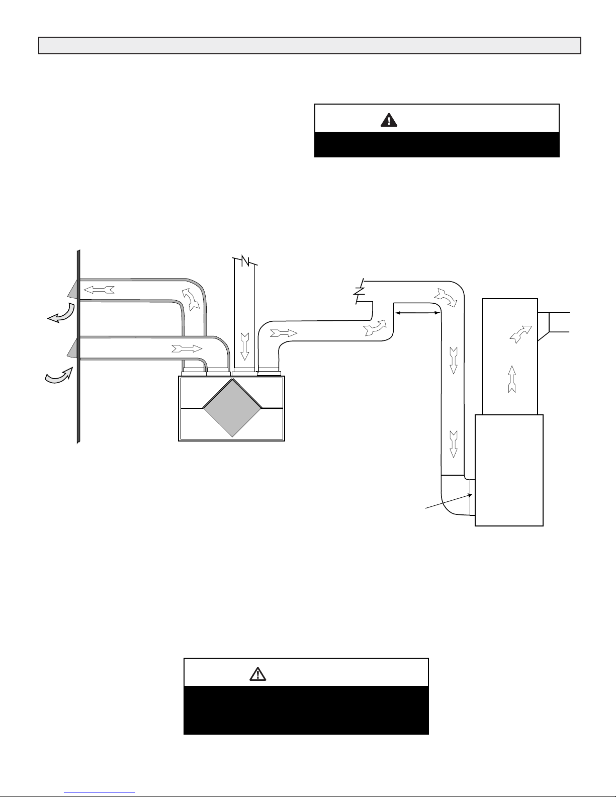
Direct Connection to Air Handler Duct System
Should you wish to hard duct the fresh air from the HRV
directly into the cold air return of the air handler, remember
to check the air flow balance of the HRV with the air handler fan both "ON" and "OFF" to determine that it does not
imbalance the unit more than 10%.
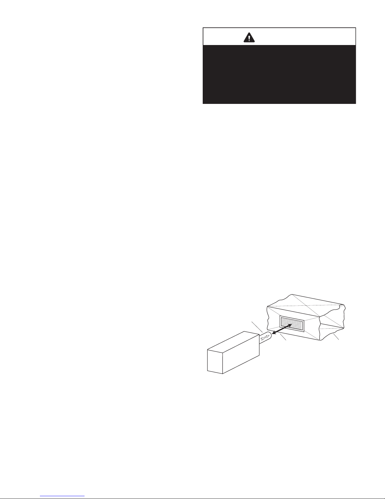
Indirect Connection to Air Handler Duct System
If permitted by local codes, an indirect connection may
be made between the HRV fresh air duct and the air handler return plenum. The fresh air from the unit may be
directed at a grille installed in the cold air return duct of the
air handler. The fresh air outlet from the HRV should be no
closer than 4 inches (100mm) and no more than 12 inches
(300mm) from the grille.
WARNING
Include a short length of fabric, flex duct or
other non-metallic connector in the “Fresh Air to
Building” hard ducted line in order to keep the
HRV separately grounded (electrically) from the
air handler. This will avoid a possible shock
hazard to service people if a short to ground
develops in one of the devices.
FRESH AIR
FROM HRV
HRV
4" MINIMUM
12" MAXIMUM
RETURN AIR
DUCT FOR
AIR HANDLER
7
Stale Air Exhaust System
The stale air exhaust system draws air from the points in
the house where the worst air quality problems occur.
Stale air ducts should be installed in the bathroom,
kitchen, and laundry room. Applications such as greenhouses, atriums, swimming pools, saunas, etc. have
unique ventilation requirements which should be
addressed with an isolated ventilation system. Also, the air
handler return duct may be used to exhaust from. In this
method, the exhaust air is not ducted back to the HRV with
"dedicated lines" from bathrooms, kitchens, etc. Instead,
the exhaust air is drawn out of the cold air return of the air
handler. The air handler blower must be running when
the unit is operating for this system to be effective.
Balancing Dampers and Grilles
Balancing dampers and/or adjustable grilles should be
used to balance the flow rates into and out of various
rooms.
Grilles or diffusers should be positioned high on the wall or
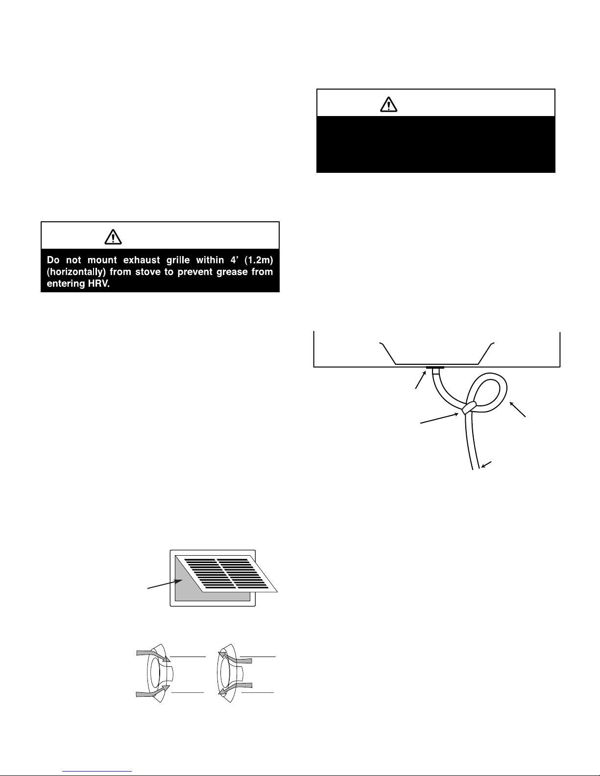
in the ceiling. Kitchen exhaust grilles must never be connected to a range hood. They should be installed at least 4
feet (1.2m) horizontally away from the stove. A hinged
6”X10” (150 X 250mm) rectangular kitchen exhaust grille is
available as part number. This grille includes a removable
grease filter. Canadian building codes require that kitchen
grilles be equipped with washable filters.
Field-supplied balancing dampers should be installed
external to the unit to balance the amount of stale air
being exhausted with the amount of fresh air being
brought into the house. Refer to Air flow Balancing section.
The Round Diffuser is available in
4" (100mm)
5” (125mm)
6" (150mm)
8" (200mm)
Drain Connection (HRV Only)
During a defrost cycle, the HRV may produce some condensation. This water should flow into a nearby drain, or
be taken away by a condensate pump.
The HRV cabinet has prepunched holes for the drain (see
below). Insert the drain spout through the hole in the drain
pan. Make certain the rubber washer is on the drain spout
before inserting.
Construct a P-Trap by looping the condensate hose and
taping in place.
Pour a cup of water into the P-Trap to create a water seal
which will prevent odours from being drawn up the hose
and into the fresh air supply to the HRV.
AIR FLOW
SUPPLY
AIR FLOW
EXHAUST
Kitchen Grille
REMOVABLE
FILTER
"P" Trap (HRV only)
CAUTION
CAUTION
The HRV and all condensate lines must be
installed in a space where the temperature is
maintained above the freezing point or freeze
protection must be provided.
DRAIN
SPOUT
TAPE
DRAINPAN
1/2"I.D.
DRAINHOSE
TODRAIN
8
DIRECTCONNECTIONoftheSUPPLYAIRSTREAMtotheAIRHANDLERCOLDAIRRETURN
(Staleairdrawnfromkeyareasofhome)
Air
Handler
Outdoors
*UnitisnormallybalancedonHIGHspeed
withairhandlerblowerON.
Highefficiencyfilter
orelectronicaircleaner
CoolAir
Return
NOTES:
1.AirhandlerblowermayberequiredtooperatewhenHRVisontoprovidegoodairdistribution.
2.Weatherhoodarrangementisfordrawingpurposesonly.6'(2m)minimumseparationrequired.
18"(460mm)abovegrademinimumoraboveanticipatedsnowlevel.
3.DuetothedifferencesinpressurebetweentheHRVandtheequipmentitisbeing
connectedto,theHRVairflowmustbeconfirmedonsite,usingthebalancing
procedurefoundintheinstallationmanual.
ReturnAir
3'min.
recommended
Weatherhoodarrangement-requiresaminimum
of6'(2m)separationandaminimumof18"(460mm)
clearanceabovegradeoranticipatedsnowlevel.
CAUTION
● Staleairdrawnfromkeyareasof
home(bathroom,kitchen,laundry)
● Freshairsuppliedtoreturn
airductofairhandler
HRVmustbebalanced.
WARNING
StaleAirToOutside
FreshAirFromOutside
STALEAIRfromvariouspartsofhome.
i.e.bathrooms(ifrequired),kitchens(ifrequired).
FreshAirToBuilding
Application Illustrations Partially Dedicated System for HRV
 Loading...