

Tradewinds RNC10, RNC95, RNC20 Installation Instructions Manual

Package 1 of 1 contains:
1 - Assembled ventilator
1 - Bag assembly containing:
2 - Drain spout assemblies (HRV units only)
4 - Hanging straps
1 - Installation manual
Installation Tools
• tin snips • large zip ties
• assorted screw drivers • fabric flexible duct
• electric drill - class I rated
• hammer • mastic tape
• wire strippers • alum. foil duct tape
• knife • zip ties
• caulking gun • 1/2” I.D. drain hose
• smoke pencil
Balancing Tools
• Pitot Tube Balancing Kit [Case, 8 ft. vinyl tubing, Pitot
tube, magnehelic gauge (0 - 0.25”), and mounting plate]
• Pitot Tube with instructions and Digital Manometer (with
resolution of 0 - 0.25” - must read to 1/100ths of an
inch)
Optional Accessories
• 20 Minute Fan Timer
• Wall Mounted Dehumidistat
• Weather hood Kit
• Round Diffuser
4” (100mm)
6” (150mm)
8” (200mm)
• Kitchen Grille
- may be required by code for kitchen applications
- contains removable grease filter
Heat Recovery Ventilators (HRV) are designed to provide
fresh air while exhausting an equal amount of stale air.
The HRV is equipped with an aluminum core. The device
uses the stale air that is being exhausted to condition the
fresh air as it is being brought in.
These instructions are intended as a general guide and do
not supersede local codes in any way. Consult authorities
who have jurisdiction before installation.
Shipping and Packaging List ............................................1
Required Tools .................................................................1
Application ........................................................................1
General .............................................................................1
Engineering Data...........................................................2-4
RNC95 Specifications and Airflow ....................................5
Clearances & Requirements.............................................6
Installation .....................................................................6-9
Application Illustrations..............................................10-12
Electrical ........................................................................13
Remote Control Devices.................................................14
Wiring the Controls .........................................................15
Operation ........................................................................16
Wiring Diagrams .............................................................17
Interlocking HRV to Furnace...........................................18
Air Flow Balancing.....................................................20-21
Troubleshooting ..............................................................22
Maintenance ..................................................................23
Shipping and Packing List
Application
General
Table of Contents
Required Tools
* LEAVE FOR HOMEOWNER
NOTE: Due to ongoing research and product development, specifications,
ratings and dimensions are subject to change without notice.
TW-01
0307
HEAT RECOVERY VENTILATOR
MODELS RNC95/RNC10/RNC20
TM
HEAT RECOVERY VENTILATOR
INSTALLATION INSTRUCTION FOR HEAT RECOVERY VENTILATOR (HRV)
2
THERMALLY CONDUCTIVE, PATENTED ALUMINUM CORE
The cross-flow heat recovery core transfers heat between the two air streams.
It is easily removed for cleaning or service.
MOTORS AND BLOWERS
Each air stream has one centrifugal blower driven by a common PSC motor.
FILTERS
Washable air filters in exhaust and supply air streams.
MOUNTING THE HRV
Four threaded inserts at corners of case designed to accept four PVC reinforced polyester straps
that are supplied with the unit.
DEFROST
Recirculating defrost system.
CASE
Twenty gauge prepainted galvanized steel (G60) for superior corrosion resistance. Insulated to
prevent exterior condensation. Drain connections two - 1/2" (12mm) OD.
WEIGHT
52 lbs. (23.6 kg)
SHIPPING WEIGHT
56 lbs. (25.4 kg)
CONTROLS - HRV System Control
HRV defaults to LOW SPEED when plugged in. HIGH SPEED option is accessible by connecting
remote controls to designated terminals inside electrical box of HRV.
Standard LOW SPEED SETTING can be increased to medium low.
Off (Standby)/Low or OFF/HIGH speed operation is also available.
OPTIONAL ACCESSORIES
99-101 Crank Timer
99-116 Dehumidistat Ventilation Control - Dehumidistat with ON/OFF
99-130 Dehumidistat Control - Dehumidistat
99-132 20 Minute Fan Timer - (3 wire) 20 gauge wire (min.) 100’ length (max.)
99-186 Weatherhoods, Two - 6" (150mm) c/w 1/4" (6mm) mesh screen
99-2040 20/40 ON/OFF Dehumidistat
99-RECIRC Recirculation Control
All units conform to CSA and UL standards.All units conform to CSA and UL standards.
WARRANTY
Units carry a 15 year warranty on the heat recovery core and a five year replacement
parts warranty.
TW-RNC95
0107
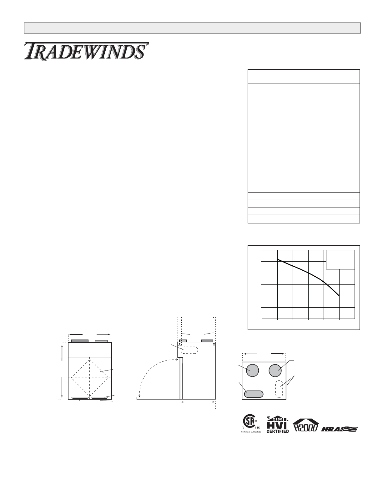
Engineering Data - HRV RNC95
Dimensions RNC95 inches (mm)
HEAT RECOVERY VENTILATOR
Date: ___________________________________________
Tag: _____________________Qty:___________________
Project: _________________________________________
Engineer: _______________________________________
Contractor: ______________________________________
Supplier: ________________________________________
Quote#: _________________________________________
Submitted by: ____________________________________
*Sensible Efficiency - thermal **Latent Efficiency - moisture
Note: Effectiveness - based on temp. differential between the 2 airstreams
Efficiency - takes into account all power inputs
Performance (HVI certified)
Net supply air flow in cfm (L/s) against external static pressure
E.S.P
(external static pressure) [cfm (L/s)]
@ 0.1" (25 Pa) 76 (36)
@ 0.2" (50 Pa) 73 (34)
@ 0.3" (75 Pa) 70 (33)
@ 0.4" (100 Pa) 66 (31)
@ 0.5" (125 Pa) 60 (29)
Max. Temperature Recovery 88%
Sensible Effectiveness
@ 60 cfm (28 L/s) 32°F (0°C) 88%
*Sensible Efficiency
@ 60 cfm (28 L/s) 32°F (0°C) 75%
*Sensible Efficiency
@ 62 cfm (29 L/s) -13°F (-25°C) 68%
VAC @ 60HZ 120
WATTS / Low speed. 60
WATTS / High speed 150
Amp rating 0.9
5 - High Speed
TM
HEAT RECOVERY VENTILATOR
24.5"
(622 mm)
18.5"
(470 mm)
Removable
Heat Recovery
Core
Drain Pan
Drain spout
FRONT TOP
knockout for
side mounting of
EXHAUST return port
6" round collar
converted to oval
minimum
18 inches (459 mm)
required for
service access
SIDE
Hanging
straps (4)
16"
(406 mm)
Threaded
inserts (4)
at corners
SUPPLY
Fresh air
from outside
5" round collar
SUPPLY
Fresh air
to building
6" round
(conv. to oval)
collar
80
5
75
70
65
Air Flow (c fm)
60
55
50
0 0.1 0.2 0.3 0.4 0.5 0.6
18.5"
(470 mm)
Static Pressure (in w.g.)
EXHAUST
Stale Air
to outside
5" round collar
EXHAUST
Return air
from building
Choice of port location
Knockouts on top and
side of unit (use 1 only)
6" round (conv. to oval)
collar supplied
3
THERMALLY CONDUCTIVE, PATENTED ALUMINUM CORE
The cross-flow heat recovery core transfers heat between the two air streams. It is easily removed
for cleaning or service.
MOTORS AND BLOWERS
Each air stream has one centrifugal blower driven by a common PSC motor.
FILTERS
Washable air filters in exhaust and supply air streams.
MOUNTING THE HRV
Four threaded inserts at corners of case designed to accept four PVC reinforced polyester straps
that are supplied with the unit.
DEFROST
Damper defrost system; defrosts automatically as the outdoor temperature falls.
CASE
Twenty gauge prepainted galvanized steel (G60) for superior corrosion resistance. Insulated to
prevent exterior condensation. Drain connections two - 1/2" (12mm) OD.
WEIGHT
63 lbs. (28.7 kg)
SHIPPING WEIGHT
67 lbs. (30.4 kg)
CONTROLS - HRV System Control
HRV defaults to LOW SPEED when plugged in. HIGH SPEED option is accessible by connecting
remote controls to designated terminals inside electrical box of HRV.
Standard LOW SPEED SETTING can be increased to medium low.
Off (Standby)/Low or OFF/HIGH speed operation is also available.
OPTIONAL ACCESSORIES
99-101 Crank Timer
99-116 Dehumidistat Ventilation Control - Dehumidistat with ON/OFF
99-130 Dehumidistat Control - Dehumidistat
99-132 20 Minute Fan Timer - (3 wire) 20 gauge wire (min.) 100’ length (max.)
99-186 Weatherhoods, Two - 6" (150mm) c/w 1/4" (6mm) mesh screen
99-2040 20/40 ON/OFF Dehumidistat
All units conform to CSA and UL standards.
WARRANTY
Units carry a 15 year warranty on the heat recovery core and a five year replacement
parts warranty.
0107
*Sensible Efficiency - thermal **Latent Efficiency - moisture
Note: Effectiveness - based on temp. differential between the 2 airstreams
Efficiency - takes into account all power inputs
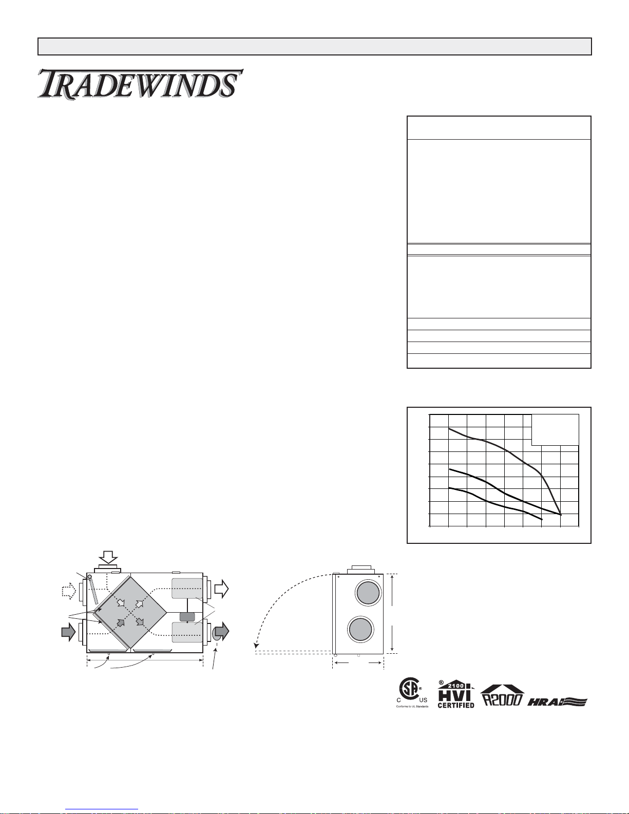
Engineering Data - HRV RNC10
Dimensions HRV inches (mm)
HEAT RECOVERY VENTILATOR
Date: ___________________________________________
Tag: _____________________Qty:___________________
Project: _________________________________________
Engineer: _______________________________________
Contractor: ______________________________________
Supplier: ________________________________________
Quote#: _________________________________________
Submitted by: ____________________________________
Performance (HVI certified)
Net supply air flow in cfm (L/s) against external static pressure
E.S.P
(external static pressure) [cfm (L/s)]
@ 0.1" (25 Pa) 177 (83)
@ 0.2" (50 Pa) 164 (77)
@ 0.3" (75 Pa) 156 (73)
@ 0.4" (100 Pa) 143 (67)
@ 0.5" (125 Pa) 123 (58)
@ 0.6" (150 Pa) 100 (47)
@ 0.7" (175 Pa) 38 (18)
Max. Temperature Recovery 78%
Sensible Effectiveness
@ 67 cfm (32 L/s) 32°F (0°C) 76%
*Sensible Efficiency
@ 67 cfm (32 L/s) 32°F (0°C) 66%
*Sensible Efficiency
@ 68 cfm (32 L/s) -13°F (-25°C) 60%
VAC @ 60HZ 120
WATTS / Low speed. 63
WATTS / High speed 173
Amp rating 1.4
3 - High Speed
*2 - Medium Low Speed
*1 - Low speed
TM
HEAT RECOVERY VENTILATOR
FRESH AIR
DEFROST
DAMPER
DEFROST
PORT
FROM OUTSIDE
*All Duct Connections 6"(150mm)
STALE AIR
TO OUTSIDE
200
180
3
160
140
120
2
100
Air Flow (cfm)
1
80
60
40
20
0 0.1 0.2 0.3 0.4 0.5 0.6 0.7 0 .8
Static Pressure (in w.g.)
*Manufacturer’s Data
FILTERS
STALE AIR
FROM INSIDE
CONDENSATE DRAINS
33-5/8"
BALANCING DAMPER
BLOWERS
FRESH AIR
TO INSIDE
*NOTE:
Front clearance of
25 inches (635 mm)
is recommended
for servicing unit.
19"
(483)
14 3/4"
(375)
4
0107
THERMALLY CONDUCTIVE, PATENTED ALUMINUM CORE
The cross-flow heat recovery core transfers heat between the two air streams.
It is easily removed for cleaning or service.
MOTORS AND BLOWERS
Each air stream has one centrifugal blower driven by a common PSC motor.
FILTERS
Washable air filters in exhaust and supply air streams.
MOUNTING THE HRV
Four threaded inserts at corners of case designed to accept four PVC reinforced
polyester straps that are supplied with the unit.
DEFROST
Damper defrost system; defrosts automatically as the outdoor temperature falls.
CASE
Twenty gauge prepainted galvanized steel (G60) for superior corrosion resistance. Insulated to
prevent exterior condensation. Drain connections two - 1/2" (12mm) OD.
WEIGHT
63 lbs. (28.7 kg)
SHIPPING WEIGHT
67 lbs. (30.4 kg)
CONTROLS - HRV System Control
HRV defaults to LOW SPEED when plugged in. HIGH SPEED option is accessible by connecting
remote controls to designated terminals inside electrical box of HRV.
Standard LOW SPEED SETTING can be increased to medium low.
Off (Standby)/Low or OFF/HIGH speed operation is also available.
OPTIONAL ACCESSORIES
99-101 Crank Timer
99-116 Dehumidistat Ventilation Control - Dehumidistat with ON/OFF
99-130 Dehumidistat Control - Dehumidistat
99-132 20 Minute Fan Timer - (3 wire) 20 gauge wire (min.) 100’ length (max.)
99-186 Weatherhoods, Two - 6" (150mm) c/w 1/4" (6mm) mesh screen
99-2040 20/40 ON/OFF Dehumidistat
All units conform to CSA and UL standards.
WARRANTY
Units carry a 15 year warranty on the heat recovery core and a five year replacement
parts warranty.
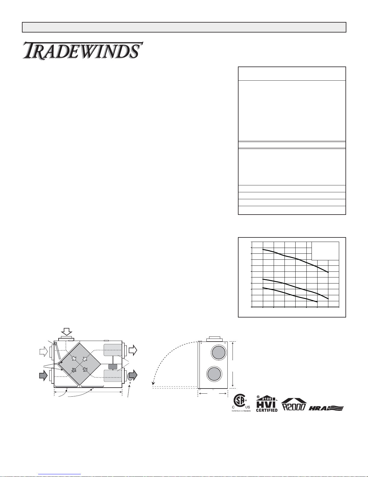
Engineering Data - HRV RNC20
Dimensions HRV inches (mm)
HEAT RECOVERY VENTILATOR
Date: ___________________________________________
Tag: _____________________Qty:___________________
Project: _________________________________________
Engineer: _______________________________________
Contractor: ______________________________________
Supplier: ________________________________________
Quote#: _________________________________________
Submitted by: ____________________________________
*Sensible Efficiency - thermal **Latent Efficiency - moisture
Note: Effectiveness - based on temp. differential between the 2 airstreams
Efficiency - takes into account all power inputs
Performance (HVI certified)
Net supply air flow in cfm (L/s) against external static pressure
E.S.P
(external static pressure) [cfm (L/s)]
@ 0.1" (25 Pa) 214 (101)
@ 0.2" (50 Pa) 206 (97)
@ 0.3" (75 Pa) 193 (91)
@ 0.4" (100 Pa) 184 (87)
@ 0.5" (125 Pa) 170 (80)
@ 0.6" (150 Pa) 155 (73)
@ 0.7" (175 Pa) 137 (65)
Max. Temperature Recovery 69%
Sensible Effectiveness
@ 119 cfm (56 L/s) 32°F (0°C) 67%
*Sensible Efficiency
@ 119 cfm (56 L/s) 32°F (0°C) 60%
*Sensible Efficiency
@ 117 cfm (55 L/s) -13°F (-25°C) 60%
VAC @ 60HZ 120
WATTS / Low speed. 70
WATTS / High speed 182
Amp rating 1.4
1
2
3
3 - High Speed
*2 - Medium Low Speed
*1 - Low speed
TM
HEAT RECOVERY VENTILATOR
240
220
200
180
160
140
120
Air Flow (c fm)
100
80
60
40
20
0 0.1 0.2 0.3 0.4 0.5 0.6 0.7 0 .8
Static Pressure (in w.g.)
*Manufacturer’s data
FRESH AIR
FROM OUTSIDE
DEFROST
DAMPER
DEFROST
PORT
FILTERS
STALE AIR
FROM INSIDE
CONDENSATE DRAINS
33-5/8"
*All Duct Connections 6"(150mm)
BALANCING DAMPER
STALE AIR
TO OUTSIDE
BLOWERS
FRESH AIR
TO INSIDE
*NOTE:
Front clearance of
25 inches (635 mm)
is recommended
for servicing unit.
14 3/4"
(375)
19"
(483)
5
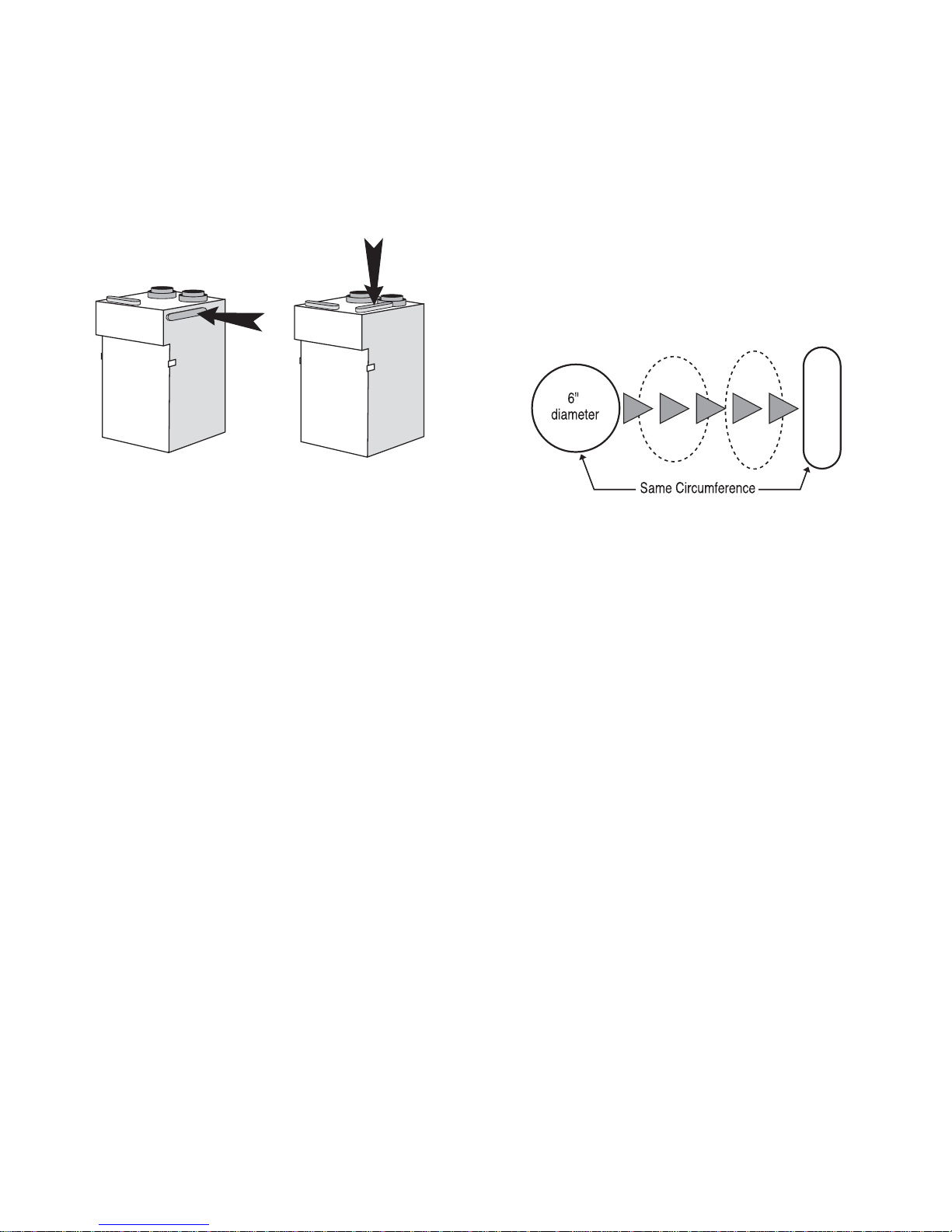
RNC95 Specifications
The RNC95 Heat Recovery Ventilator (HRV) has been
designed to allow the installer to choose between two possible positions on the cabinet for the INDOOR EXHAUST
(return from building) port. Illustrations in this manual show
standard (side mounted) port location. The same specifications apply to both RNC95 setups, regardless of which
port position is selected.
Variable Port Location / Installation (Model RNC95
only)
The exhaust return port collar is not factory installed.
Installer may choose either side mounted or alternate top
mounted port by simply removing one of the two knock-out
plates and attaching a port collar (supplied). To remove
knock-out plate, insert a utility knife into the knock-out slits
and trace them completely to puncture protective film
underneath. Then, cut the solid tabs between the slits,
using tin snips or side cutters, and remove the knock-out
plate. If any protective film still blocks the opening, remove
it now.
In order to make the RNC95 as space efficient as possible, the INDOOR supply and return ports are converted
from round to oval shape. Overall size of the port remains
the same. Simply bend a standard duct fitting to the correct shape, and attach to the oval port using the same
method as for a round port.
RNC95 Air Flow
Stale air enters the FRONT RIGHT side port. The air will
pass down the front half of the core, then up the back half
of the core and out the RIGHT REAR port.
Fresh outdoor air will enter the LEFT REAR port and pass
down the back half of the core. It will then pass up the
front half of the core, and out the LEFT FRONT port.
This unique configuration allows the air to actually travel
through the core twice, making the RNC95 almost as efficient as a double core unit.
Variable Port Location
SIDE MOUNTED PORT TOP MOUNTED PORT
standard location alternate location
Round port bent to oval
6
Location Selection
The HRV must be located in a heated space where it will
be possible to conveniently service the unit. Typically the
HRV would be located in the mechanical room or an area
close to the outside wall where the weather hoods will be
mounted. If a basement area is not convenient or does not
exist, a utility or laundry room may be used.
Attic installations are not normally recommended due to:
A) the complexity of work to install
B) freezing conditions in the attic
C) difficulty of access for service and cleaning
The HRV unit must be installed in a horizontal position as
shown in the illustration below. The unit should be suspended using the provided hanging straps. If necessary,
the unit may be installed on a platform: however, the cabinet should be isolated from the platform to prevent
vibration transmission. The unit must be level. Sufficient
clearance at the front of the access door is required for
servicing the air filters and core. A minimum of 25"
(635mm) clearance is recommended so the door can be
opened. Four PVC reinforced polyester hanging straps are
provided for hanging the HRV from the basement floor
joists.
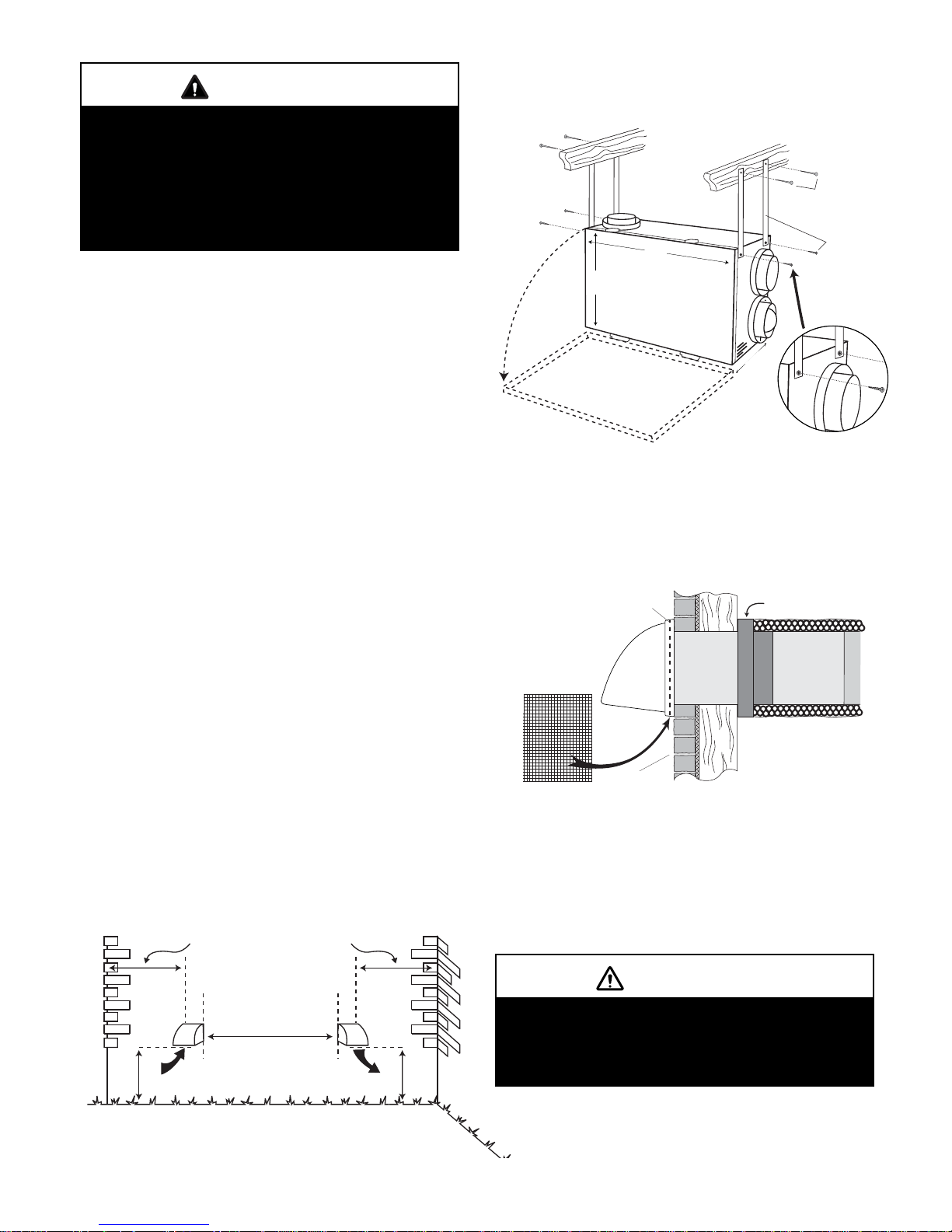
Suspending the Unit
The hanging straps should be attached to the unit at the
top end corners (mounting screws are already located on
the HRV case). Securely fasten the other end of the straps
to the floor joists with wide head nails (not supplied), making sure the UNIT IS LEVEL. The straps are designed to
reduce the possibility of noise, resonance or harmonics;
therefore using the full length of the strap between the
HRV and the floor joists is recommended.
Weatherhood Location and Installation
Weatherhood kit includes two fixed-cover hoods with a
1/4” (6mm) mesh screen.
Exhaust Weatherhood Requirements
• At least 6' (2 m) from the ventilation air intake*
• At least 18" (460mm) above ground or above the
depth of expected snow accumulation*
Installation
Connecting Appliances to the HRV
The following appliances should not be connected to the
HRV:
• clothes dryer
• range top
• stovetop fan
• central vacuum system
NOTE: Connecting any of these to the HRV will invalidate your warranty.
Clearances and Requirements
WARNING
Before installation, careful consideration must
be given to how this system will operate if
connected to any other piece of mechanical
equipment, i.e. a forced air furnace or air handler,
operating at a higher static. After installation, the
compatibility of the two pieces of equipment
must be confirmed, by measuring the air flows of
the ventilator, by using the balancing procedure
found in this manual.
It is always important to assess how the operation
of any HRV may interact with vented combustion
equipment (i.e. Gas Furnaces, Oil Furnaces,
Wood Stoves, etc.)
NEVER install a ventilator in a situation where its
normal operation, lack of operation or partial
failure may result in the backdrafting or improper
functioning of vented combustion equipment!
CAUTION
Lint, dust or grease will collect in the HRV
damaging the unit.
WARNING
Improper installation, adjustment, alteration,
service or maintenance can cause property
damage, personal injury or loss of life.
Installation and service must be performed by a
qualified installer or service agency.
WARNING
Electric shock hazard. Can cause
injury or death. Before attempting to
perform any service or maintenance,
turn the electrical power to unit OFF
at disconnect switch(es). Unit may
have multiple power supplies.
7
• At least 3' (1 m) away from the corner of the building*
• At least 3’ away from gas meter, electric meter or a
walkway where fog or ice could create a hazard*
• Not into a garage, workshop or other unheated space
When installing the weatherhood, its outside perimeter
must be sealed with exterior caulking.
* Local code may require greater distances.
Intake Weatherhood Requirements
• Should be located upstream (if there are prevailing
winds) from the exhaust outlet
• At least 6' (2 m) from the exhaust weather hood *
• At least 6' (2 m) away from dryer vents and air handler
exhaust (medium or high efficiency furnaces)*
• A minimum of at least 6' (2 m) from driveways, oil fill
pipes, gas meters, or garbage containers, swimming
pools*
• At least 18" (460mm) above the ground, or above the
depth of expected snow accumulation*
• At least 3' (1 m) from the inside/outside corner of the
building*
• Do not locate in a garage, attic or crawl space
* Local code may require greater distances.
Weatherhood Clearances
Suspending the Unit using the
Provided Hanging Straps
CAUTION
Weatherhood Installation
Unit must be installed level to ensure proper
condensate drainage. Due to the broad range of
installation and operational conditions,
consideration must be given for the possibility
of condensation forming on the unit or
connecting ducting. Objects below the
installation may be exposed to condensate.
OUTSIDE CORNER
36" (1m)
recommended min.
36" (1m)
recommended min.
INSIDE CORNER
31"
(787)
19"
(483)
*NOTE:
Frontclearanceof
25inches(635mm)
isrecommended
forservicingunit.
Unitisdesignedforhorizontal
installationonlyasshown.
Usingfulllengthhangerstrapsis
recommendedforvibrationcontrol,
butcanbeshorterifrequired.
SCREEN
(sideview)
12"galvanized
pipesupplied
EXTERIOR
1/4"(6mm)SCREEN
(frontview)
WALL
1. ThermalCollarslidesovergalvanized
sleeveofWeatherhood.
2. FastenThermalCollartoBelt.
3. SlidetheInsulatedFlexibleDuctingover
theWeatherhood'sgalvanizedsleeveand
fastenittotheThermalCollar.
4. Hoodishingedtoallowforeasyaccess
forcleaningofbirdscreen.
WideHeadNails
WIDEHEAD
(notsupplied)
NAILS
(notsupplied)
STRAPS
AND
SCREWS
(supplied)
DETAIL
143/4"
(375)
COLLARISSUPPLIEDTO
ENSUREVAPOURBARRIER
IS100%SEALEDTO
WALLPLATE
6' (2m)
INTAKE
18" (460mm) min.
recommended min.
EXHAUST
18" (460mm) min.
CAUTION
Weatherhood arrangement - requires a minimum of 6'
(2m) separation and a minimum of 18" (460mm)
clearance above the higher of the grade or anticipated
snow level.
8
Air Duct Design and Installation
A well designed and installed ducting system will allow the
HRV to operate at its maximum efficiency.
Always try to keep duct runs as short and straight as possible. See Installation Diagrams for various installation
options.
The inner and outer liners of the flexible insulated duct
must be clamped to the sleeve of the weatherhoods (as
close to the outside as possible) and the appropriate port
on the HRV. It is very important that the fresh air intake
line be given special attention to make sure it is well
sealed. A good bead of high quality caulking (preferably
silicone sealant) will seal the inner flexible duct to both the
HRV port and the weather hood prior to clamping with a
large zip tie.
To minimize air flow restriction, the flexible insulated duct
that connects the two outside weather hoods to the HRV
should be stretched tightly and be as short as possible.
Twisting or folding the duct will severely restrict air flow.
See below for the recommended connection of flexible
insulated ducts to the the outside weatherhoods and the
HRV.
Installing the Ducting Between the HRV &
Living Areas in the House
To maximize airflow in the duct system, all ducts should
be kept short and have as few bends or elbows as possible. Forty-five degree elbows are preferred to 90° elbows.
Use “Y” tees instead of 90° elbows whenever possible.
All duct joints must be fastened with screws, rivets or duct
sealant and wrapped with mastic or a quality duct tape to
prevent leakage. Mastic is preferred but if duct tape is
used, we recommend aluminum foil duct tape.
Galvanized ducting from the HRV to the living areas in the
house is recommended whenever possible, although flexible duct can be used in moderation if necessary.
To avoid possible noise transfer through the duct system,
a short length (approximately 12 inches or 300mm) of nonmetallic flexible insulated duct should be connected
between the HRV and the supply/exhaust duct system.
The main supply and return lines to/from the HRV must be
6 inches (150mm) minimum. Branch lines to the individual
rooms may be as small as 4 inches (100mm), but 5 inch
(125mm) lines are preferred .
All ducts running through attics and unheated spaces must
be sealed and insulated to code.
Fresh Air Ducting
In applications that do not include an air handler, fresh air
should be supplied to all bedrooms and living areas,
excluding bathrooms, kitchen and utility areas. Grilles
should be located high on a wall or in ceiling locations.
Grilles that diffuse the air comfortably such as the Round
Diffuser are recommended.
If the floor is the only option available, then special care
should be taken in locating grilles. Areas such as under
baseboard heaters will help to temper the air. Also optional inline duct heaters are available for mounting in the
supply duct work to add heat if required.
Direct Connection to Air Handler Duct System
Should you wish to hard duct the fresh air from the HRV
directly into the cold air return of the air handler, remember to check the air flow balance of the HRV with the air
handler fan both "ON" and "OFF" to determine that it does
not imbalance the unit more than 10%.
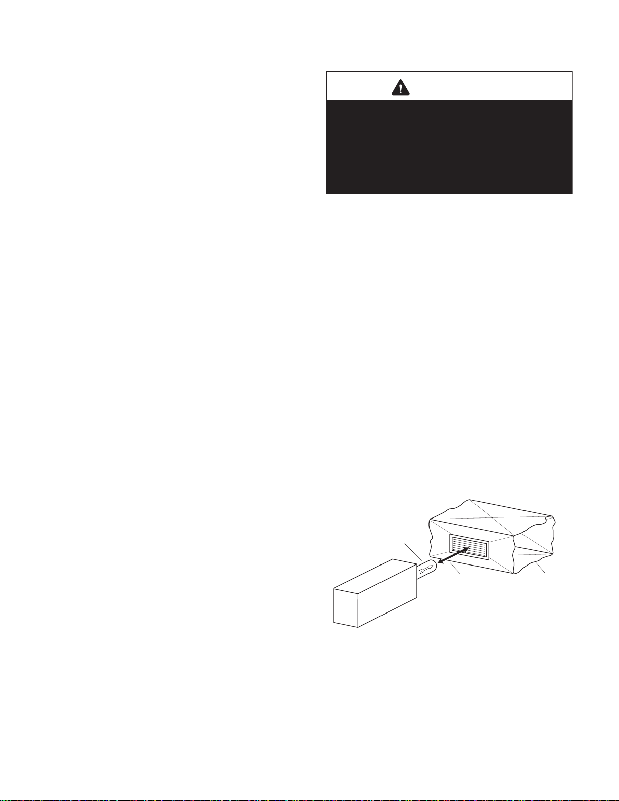
Indirect Connection to Air Handler Duct System
If permitted by local codes, an indirect connection may be
made between the HRV fresh air duct and the air handler
return plenum. The fresh air from the unit may be directed
at a grille installed in the cold air return duct of the air handler. The fresh air outlet from the HRV should be no closer
than 4 inches (100mm) and no more than 12 inches
(300mm) from the grille.
WARNING
Include a short length of fabric, flex duct or
other non-metallic connector in the “Fresh Air to
Building” hard ducted line in order to keep the
HRV separately grounded (electrically) from the
air handler. This will avoid a possible shock
hazard to service people if a short to ground
develops in one of the devices.
FRESH AIR
FROM HRV
HRV
4" MINIMUM
12" MAXIMUM
RETURN AIR
DUCT FOR
AIR HANDLER
 Loading...