

Trademaster TPF24, TPF30, TWF30 Quick Start Manual
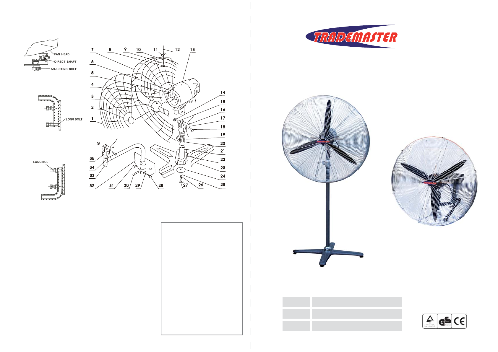
ASSEMBLING DIAGRAM
OSCILLATING CONTROL
UPWARD INSTALLATION
OF ANGLE ARM
DOWNWARD INSTALLATION
OF ANGLE ARM
®
INDUSTRIAL WORKSHOP FANS
1. FRONT GUARD
2. BLADE
3. SCREW
4. BOLT
5. SPRING WASHER
6. WASHER
7. BACK GUARD
8. NUT
9. SPRING WASHER
10. GUARD CLIP
11. GUARD CLIP
12. SCREW
13. MOTOR
14. NUT
15. WASHER
16. SCREW
17. WIRING CLIP
18. BOLT
19. FIXING COVER
20. FIXING SCREW
21. SUPPORT
22. DECORATING COVER
23. PEDESTAL
24. WASHER
25. WASHER
26. SPRING WASHER
27. BOLT
28. BOLT
29. NUT
30. BOLT
31. BOLT
32. WALL PLATE
33. SUPPORT ARM
34. FIXING SCREW
35. LOWER CONNECTION
PEDESTAL FAN
ASSEMBLING ORDER
21→23→24→25→26→27→22
→19→20→13→18→15→14→7
→6→5→4→2→3→1→10→11
→12→9→8→17→16
WALL MOUNT FAN
ASSEMBLING ORDER
35→33→34→32→30→31→29
→28→13→18→15→14→7→6
→5→4→2→3→1→10→11→12
→9→8→17→16
TPF24
TPF30
TWF30
24” / 600mm PEDESTAL FAN
30” / 750mm PEDESTAL FAN
30” / 750mm WALL MOUNT FAN
READ CAREFULLY AND UNDERSTAND THESE INSTRUCTIONS BEFORE USE.
Limited Warranty
Industrial Tool & Machinery Sales (hereinafter
refered to as ITMS) will, within twelve (12) months
from the original date of purchase, repair or replace
any goods found to be defective in materials or
workmanship.
This warranty is void if the item has been damaged
by accident, neglect, improper service or other
causes not arising out of defects in materials or
workmanship. This warranty does not apply to
machines and/or components which have been
altered, changed, or modified in any way, or
subjected to overloading or use beyond
recommended capacities and specifications. Worn
componentry due to normal wear and tear is not a
warranty claim. Goods returned defective shall be
returned prepaid freight to ITMS or agreed repair
agent, which shall be the buyer’s sole and exclusive
remedy for defective goods. ITMS accepts no
additional liability pursuant to this guarantee for the
costs of travelling or transportation of the product
or parts to and from ITMS or the service agent or
dealer, such costs are not included in this warranty.
The manufacturer reserves the right to make
improvements and modifications to design without
prior notice.
Technical Specifications
Part #
Phase
Voltage
Power
1. If an electrical fault is detected or the power
supply cord is damaged, the device must sent to a
licenced electrician for repair.
2. Guard against electric shock, avoid body
contact with earthed or grounded surfaces eg.
pipes, air con, refrigerators etc.
Never operate the device in rain or wet conditions,
or if the tool has been exposed to rain or wet
conditions.
3. Power source; ensure that the power source to
be used conforms to the power requirements
specified on the name plate.
Ensure the power supply plug matches the outlet.
Never modify the plug or use adaptors.
4. Do not abuse the power cord. Never use the
cord for carrying, pulling or unplugging the
device. Keep cord away from heat, oil, sharp edges
or moving parts. Damaged or entangled cords
increase the risk of electric shock.
5. Extension cord; when using an extension cord
ensure sufficient thickness and rated capacity.
6. The Trademaster fan is suitable for cooling in
factories, warehouses, workshops and industrial
work areas. It is not designed for domestic use.
Operating Procedures
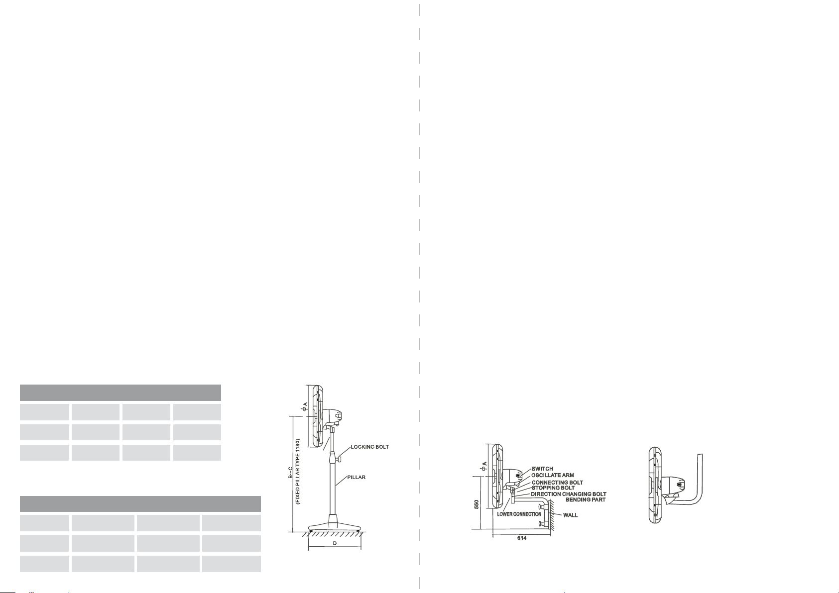
1. Oscillating control; The oscillating structure is shown in the drawing. When the oscilate arm is
secured to the centre bolt hole, the fan will not oscillate. When oscilate arm is moved to the off-centre
bolt hole, the fan will oscillate 90 degrees. Always ensure the power is turned off before making any
oscillating adjustments
5. Fan Direction; To change the direction of the fan, turn off the power, loosen the direction-changing
bolt, adjust the direction of the fan head and tighten the bolt. It is not necessary to move the base of
the fan.
6. Upward and downward tilt adjustment; Turn off the power, hold the head of the fan, loosen the
connecting bolt and stopping bolt, adjust the fan to satisfactory position and tighten up the two bolts.
19mm Spanner required ( not supplied )
7. Head Height Adjustment(pedestal type only); Turn off the power. Loosen the locking bolt, adjust
the fan head to ideal position and then tighten up the locking bolt. In order to avoid the fan head
falling down suddenly, the fan head must be held when the locking bolt is being loosened.
8. Installation of the wall fan base; The angle arm of the fan can be installed facing upwards or
downwards. In both cases, the longer of the two locking bolts must be inserted through the small hole
at the end of the angle arm in order to avoid falling off.
9. Speed Adjustment; The fan incorporates 3 speed settings which are controlled by the switch on the
back of the fan head. “0” represents stop. “1” is the lowest blade speed setting, “3” is the highest.
Maintenance
1. Grease change; After the fan is operated over 2000 hours (or at least once a year), the grease in the
gearbox and bearing should be changed.
2. Care; If the fan is not used for extended periods, it should be cleaned and put into a dry place.
TPF24
TPF30
TWF30
Installation Dimensions
Spec
TPF24
General Safety Instructions
TPF30
TWF30
1
1
1
Ф
654mm
824mm
824mm
220-240v
220-240v
220-240v
B - C
1235-1760mm
1235-1760mm
160w
280w
280w
D
600mm
700mm
-
-
PEDESTAL TYPE
WALL TYPE
 Loading...