

Trademaster RF 270S Instruction Manual
METAL CUTTING BAND SAW MACHINE
MODEL: 270S
INSTRUCTION MANUAL
050110-R0

1
Table Of Contents Page No
1 Overall Aspect …………………………………………………………………
2 Safety Rules For All Tools ……………………………………………………
3 Specification ……………………………………………………………………
4 Features ……………………………………………………………………..…
5 Transportation & Install ……………………………………………………..
6 Minimum Room Space For Machine Operation ……………………………
7 Make Proper Tooth Selection ………………………………………………..
8 BI-Metal Speeds And Feeds ………………………………………………….
9 Use Of Main Machine Parts ………………………………………………….
10 Maintaining ……………………………………………………………………
11.Trouble shooting ………………………………………………………………
12 Circuit Diagram ……………………………………………………………….
13 Parts Lists & Drawing ………………………………………………………
CAUTION
Install saw blade and blade guard
before use. Set proper blade tension
to prevent any danger caused by
damaged saw blade or work piece.
2
3
4
5
5
6
7
7
9
11
11
14
15
2
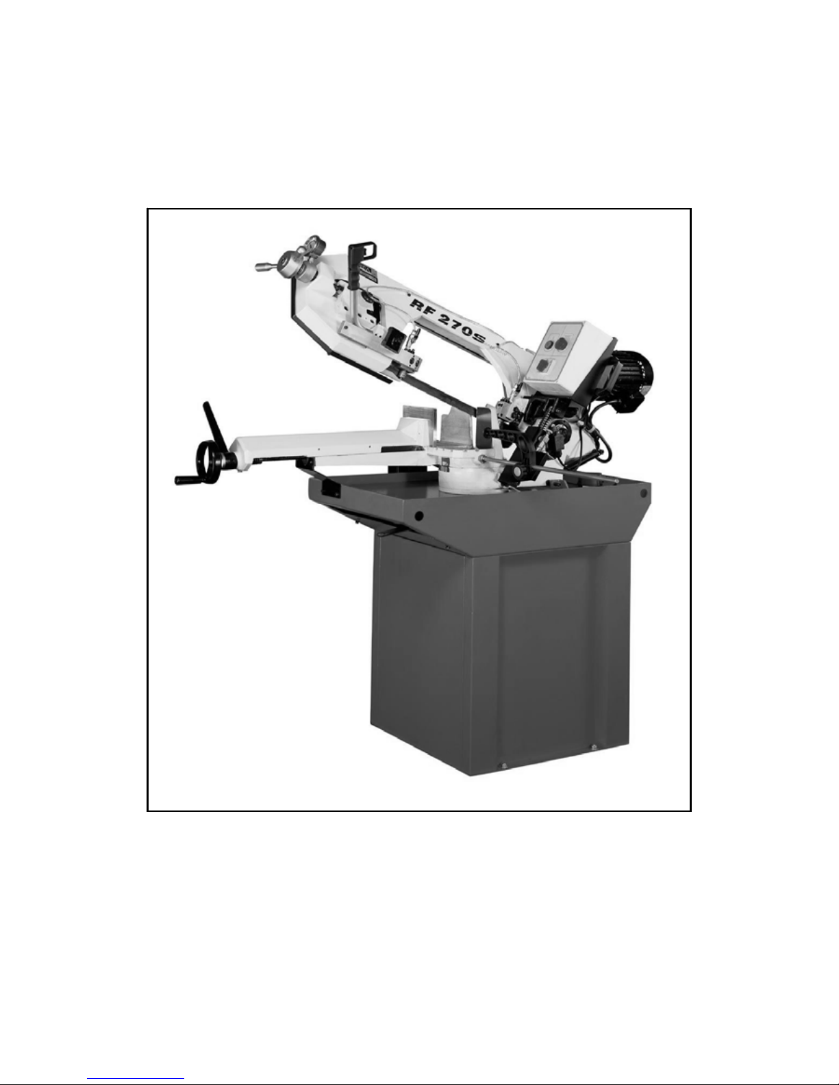
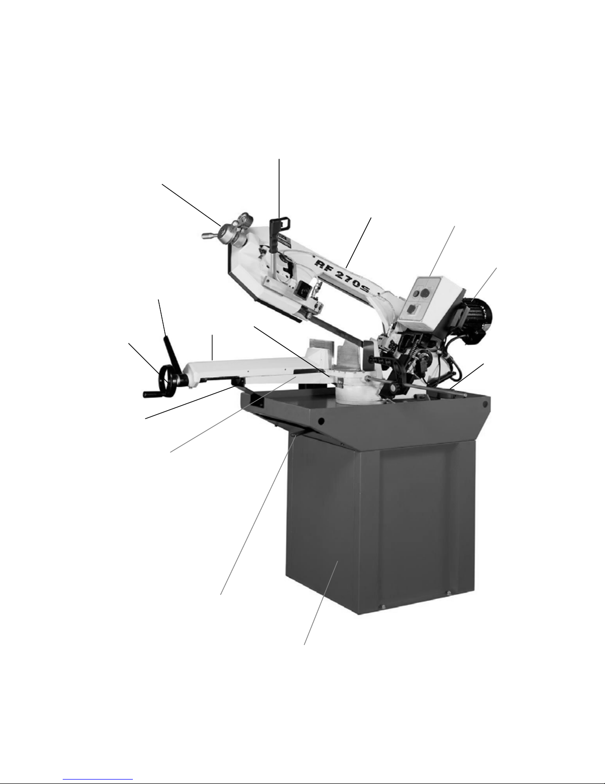
1.Overall Aspect
Saw arm
Control Panel
The blade tension handle
Motor
The start button
Coolant pump
Base
Angle Sale
Move Vise
The vise fixed handle
The move vise handle
The swivel vise base of handle
Vise base
Fixed plate

3
WARNING: FAILURE TO FOLLOW THESE RULES
MAY RESULT IN SERIOUS PERSONAL I NJU RY
As with all machinery there are certain hazards involved with operation and use of the machine. Using the machine with
respect and caution will considerably lessen the possibility of personal injury. However, if normal safety precautions are
overlooked or ignored, personal injury to the operator may result.
This machine was designed for certain applications only. We strongly recommend that this machine NOT be modified
and/or used for any application other than for which it was designed. If you have any questions relative to its application
DO NOT use the machine until you contact with us and we have advised you.
Your machine might not come with a power socket or plug. Before using this machine, please do ask your local
dealer to install the socket or plug on the power cable end.
2.SAFETY RULES FOR ALL TOOLS
A. USER:
(1). WEAR PROPER APPAREL. No loose clothing, gloves, rings, bracelets, or other jewelry to get caught in
moving parts.
Non-slip footwear is recommended. Wear protective hair covering to contain long hair.
(2). ALWAYS WEAR EYE PROTECTION. Refer to ANSLZ87.1 standard for appropriate recommendations.
Also use face or dust mask if cutting operation is dusty.
(3). DON'T OVERREACH. Keep proper footing and balance at all times.
(4). NEVER STAND ON TOOL. Serious injury could occur if the tool is tipped or if the cutting tool is accidentally
contacted.
(5). NEVER LEAVE TOOL RUNNING UNATTENDED. TURN POWER OFF. Don't leave tool until it comes to
a complete stop.
(6). DRUGS, ALCOHOL, MEDICATION. Do not operate tool while under the influence of drug, alcohol or any
medication.
(7). MAKE SURE TOOL IS DISCONNECTED FROM POWER SUPPLY. While motor is being mounted,
connected or reconnected.
(8). ALWAYS keep hands and fingers away from the blade.
(9). STOP the machine before removing chips.
(10). SHUT- OFF power and clean the BAND SAW and work area before leaving the machine.
(11).DO NOT Touch the cutting Blade while the machine is turm on.
B. USE OF MACHINE:
(1). REMOVE ADJUSTING KEYS AND WRENCHES. Form habit of checking to see that keys and adjusting
wrenches are removed from tool before turning it "on".
(2). DON'T FORCE TOOL. It will do the job better and be safer at the rate for which it was designed.
(3). USE RIGHT TOOL. Don't force tool or attachment to do a job for which it was not designed.
(4). SECURE WORK. Use clamps or a vise to hold work when practical. It's safer than using your hand frees both
hands to operate tool.
(5). MAINTAIN TOOLS IN TOP CONDITION. Keep tools sharp and clean for best and safest performance.
Follow instructions for lubricating and changing accessories.
(6). USE RECOMMENDED ACCESSORIES. Consult the owner's manual for recommended accessories. The use
of improper accessories may cause hazards.
(7). AVOID ACCIDENTAL STARTING. Make sure switch is in “OFF” position before plugging in power cord.
(8). DIRECTIONOF FEED. Feed work into a blade or cutter against the direction of rotation of the blade or cutter
only.
(9). ADJUST AND POSITION the blade guide arm before starting the cut.
(10). KEEP BLADE GUIDE ARM TIGHT, A loose blade guide arm will affect sawing accuracy.
(11). MAKE SURE blade speed is set correctly for material being cut.
(12). CHECK for proper blade size and type.
(13). STOP the machine before putting material in the vise.
(14). ALWAYS
have stock firmly clamped in vise before start i ng c ut.
(15). GROUNDALL TOOLS. If tool is equipped with three-prong plug, it should be plugged into a three-hole
electrical receptacle. If an adapter is used to accommodate atwoprong receptacle, the adapter lug must be attached to a
known ground. Never removed the third prong.

4
C. ADJUSTMENT :
MAKE all adjustments with the power off. In order to obtain the machine. precision and correct ways of adjustment
while assembling, the user should read the detailed instruction in this manual.
D. WORKING ENVIRONMENT:
(1). KEEP WORK AREA CLEAN. Cluttered areas and benches invite accidents.
(2). DON'T USE IN DANGEROUS ENVIRONMENT. Don't use power tools in damp or wet locations, or expose
them to rain. Keep work area well-lighted.
(3). KEEP CHILEREN AND VISITIORS AWAY. All children and visitors should be kept a safe distance from
work area.
(4). DON’T install & use this machine in explosive, dangerous environment.
E. MAINTENANCE:
(1). DISCONNECT machine from power source when making repairs.
(2). CHECK DAMAGED PARTS. Before further using of the tool, a guard or other part that is damaged should be
carefully checked to ensure that it will operate properly and perform its intended function. Check for alignment of
moving parts, binding of moving parts, breakage of parts, mounting, and any other conditions that may affect its
operation. A guard or other part that is damaged should be properly repaired or replaced.
(3). DISCONNECT TOOLS before servicing and when changing accessories such as blades, bits, cutters, etc.
(4). MAKE SURE that blade tension and blade tacking are properly adjusted.
(5). RE-CHECK blade tension after initial cut with a new blade.
(6). TO RPOLONG BLADE LIFE ALWAYS release blade tension at the end of each workday.
(7). CHECK COOLANT DAILY Low coolant level can cause foaming and high blade temperatures. Dirty coolant
can clog pump, cause crooked. Rust, low cutting rate and permanent blade failure. Dirty coolant can cause the growth
of bacteria with ensuing skin irritation.
(8). WHEN CUTTING MAGNESIUM NEVER use soluble oils or emulsions(oil-water mix) as water will greatly
intensify any accidental magnesium chip fire. See your industrial coolant supplier for specific coolant
recommendations when cutting magnesium.
(9). TO PRNMT corrosion of machined surfaces when a soluble on is used as coolant, pay particular attention to
wiping dry the surfaces where fluid accumulates and does not evaporate quickly, such as between the machine bed and
vise.
F. SPECTIFIED USAGE:
This machine is used only for general metals cutting within the range of cutting capacity.
G. NOISE:
A weighted sound pressure level : under80 dB.
H. SAFETY DEVICE:
Interlock switch on cutting area as soon as the cover of cutting area is open, machine will stop at once witch the
function of this switch. Do not remove this switch from machine for any reason, and check its function frequently.
3.SPECIFICATION
MOTOR 1.5HP
60Hz 48 ~ 96 MPM
Saw Blade Speed 2 Speed Motor
50Hz 40 ~ 80 MPM
Blade Size(mm) 27x0.9x2450
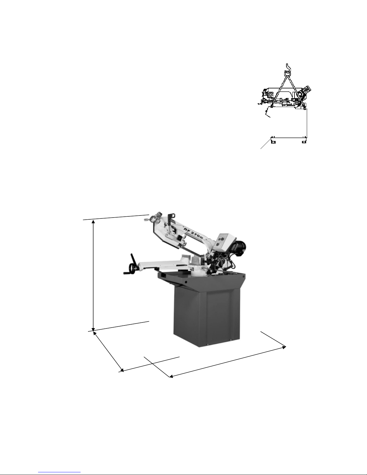
Dimension L x W x H (mm) 1420x510x1380
N.W. / G.W. (kgs) 216 / 246
Measurement 1400x560x755
Packing
Sets per 20’ CTNR 48 sets
5
Fig. A
○(mm/inch) 225 / 8.75 “
0°
□(mm/inch) 200x200 / 7.8“x7.8“
○(mm/inch) 160 / 6.25“
+ 45°
□(mm/inch) 140x140 / 5.5“x5.5“
○(mm/inch) 90 / 3.5“
Cutting
Capacity
+60°
□(mm/inch) 90x90 / 3.5“x3.5 “
4.FEARTURES:
1. This machine is useful for cutting normal steel, steel pipe, and provides cutting angle at + 60°and +45°by
the swivel head.
2. A tooth selection chart was provided on the machine for cutting reference.
3. Variable speed control gives convenient selection of speeds. (This machine comes with a standard 2-speed
motor. But can be purchased with a DC driven mot or as an opti o n. )
4. This machine is using manual cutting by pulling down the saw bow by hand. Start(press) button is located at
the handle of the saw bow. Motor stops when button was released.
5. Stability of the machine, plus working table height is 950 mm, conforming to human engineering.
6. The one-inch blade and carbide guide provide better result of the cutting surface and efficiency.
7. The one-piece casting and one time CNC processing provide better rigidity and precision of the machine.
8. The one-piece and full coverage blade cover conforms to CE stipulation. Well coolant fluid collection system
provides clean and dry, and safety of the working area.
9. Chip pan underneath the working table prevents coolant fluid leaking and keep floor dry.
10. Coolant for cutting,, water : oil = 40 : 1 oil specification.
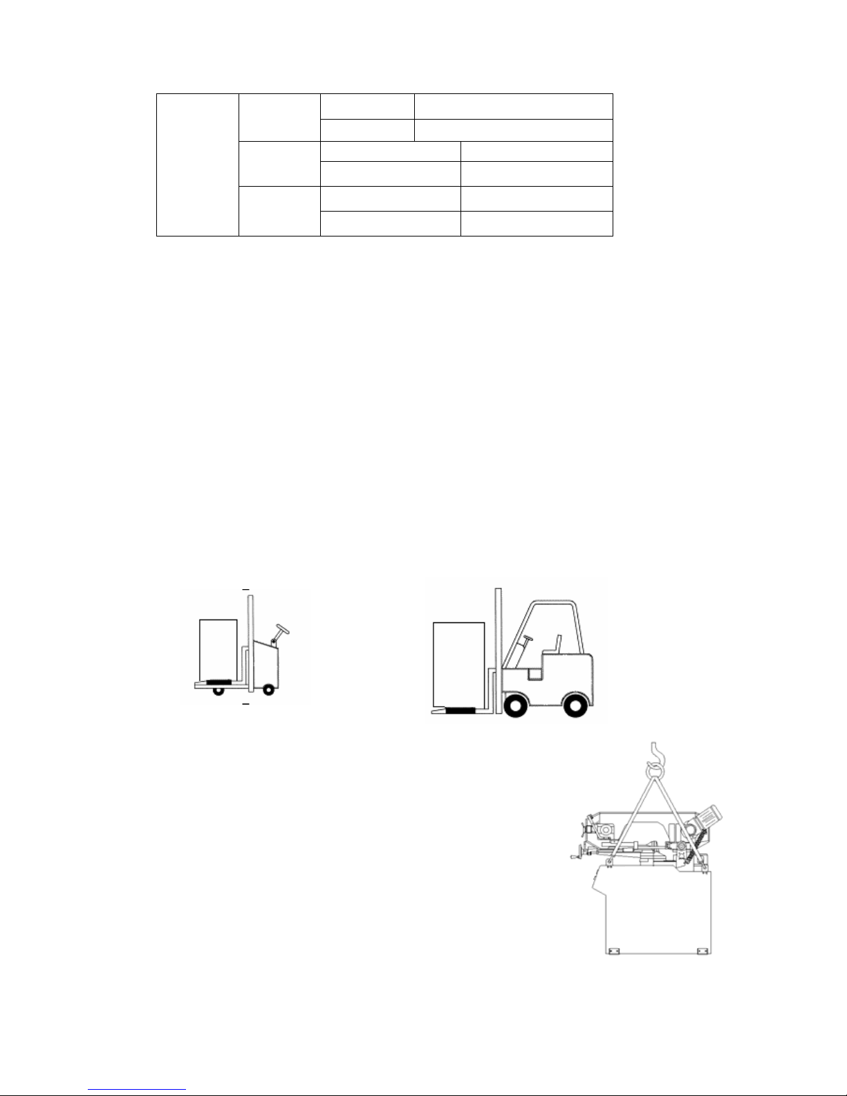
5.TRANSPORTATATION & INSTALLATION:
5-1.Unpacking
1. Transportation to desired location before unpacking, please use-lifting jack. (Fig. B)
2. Transportation after unpacking, please use heavy duty fiber belt to lift up the machine.
ALLWAYS KEEP PROPER FOOTING & BALANCE WHILE MOVING
THIS MACHINE.
5-2.TRANSPORTATION OF MACHIN E :
As this machine weights 208kgs(458.6lbs) it is recommended that the machine be
transported with help of lifting jack.
Transportation Recommendation:
1. Tighten all locks before operation.
2. Always keep proper footing & balance while moving this machine, and only
use a heavy duty of fiber belt to lift the machine as per Fig. A.
3. TURN OFF the power before wiring & be sure machine is properly grounded.
Overload & circuit breaker are recommended for safety wiring.
4. Tighten 4 bolts to base holes after
machine is balanced.
5. Check carefully if the saw blade is running in counter-
clockwise direction if not, reverse the wiring per circuit diagram,
Fig, B
6
B Fig. B
then repeat the running test.
6. Keep machine always out from sun, dust, wet, or raining area.
5-3.Installation:
(1) Always Keep proper footing & balance while m ovi ng t his 20 8 kgs m achi ne. An d
only use heavy-duty fiber belt to lift the machine as per Fig. (B).
(2) Hang the machine up, away from the floor, take away the 4 pads and assemble
them on the auxiliary stand. Fix the machine on the auxiliary stand and lock the
connection nut.
(3) Finish removing this wooden case/crate from the machine. Unbolt the machine
from the crate bottom.
(4) Position & tighten 4 bolts into base holes properly after machine in balance.
(5) Turn off the power before wiring & be sure machine is in proper grounding.
Overload & circuit breaker is recommended for safety wiring.
(6) Keep machine always out from sun, dust, wet, raining area.
5-4.CLEAIG & LURICATING
(1) Your machine has been coated with a heavy grease to protect it in shipping. This coating should be completely
removed before operating the machine. Commercial degreaser, kerosene or similar solvent may be used to
remove the grease from the machine, but avoid getting solvent on belts or other rubber parts.
(2) After cleaning, coat all bright work with a light lubricant. Lubricate all points . with a medium consistency
machine oil.
6.MINIMUM ROOM SPACE FOR MACHINE OPERATION
82.5 ”
133 ”
97.5 ”
7
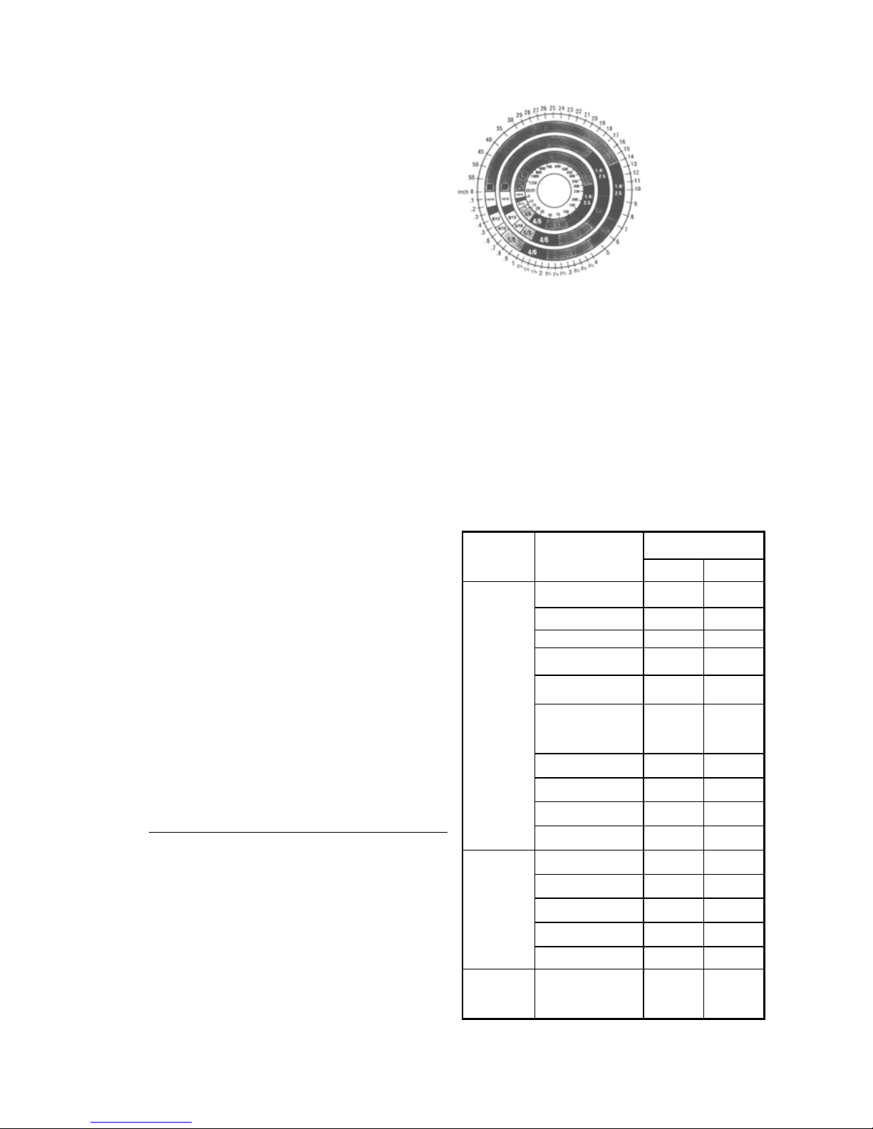
7. MAKE PROPER TOOTH SELECTION
For maximum cutting efficiency and lowest cost
per cut, it is important to select the blade with the right
number of teeth per inch (TPI) for the material being cut.
The material size and shape dictate tooth selection.
TOOTH
SELECTION
You need to consider:
The width of the cut - That is, the distance in the cut
that each tooth must travel from the point it enters the
work-piece until it leaves the work-piece, and
1.The shape of the work-piece.
z Squares, Rectangles, Flats (Symbol : ■)
Locate the width of cut on the chart. (Inches
on the outer circle and millimeters on the
inner circle.) Select the tooth pitch on the
ring marked with the square shape which
aligns with the width of cut.
EXAMPLE: 6" (150mm) square, use a 2/3
Vari-Tooth.
z Round Solids (Symbol : ●)
Locate the diameter of your work-piece on
the chart. Select the tooth pitch on the ring
marked with the round shape which aligns
with the size of stock you are cutting.
EXAMPLE: 4" (100mm) round, use a 3/4
Vari-Tooth.
z Tubing, Pipe, Structural ( Symbol : O H
^ )
Determine the average width of cut by
dividing the area of the work-piece by the
distance the saw blade must travel to finish
the cut. Locate the average width of cut on
the chart. Select the tooth Ditch on the ring
marked with the tubing and structural shape,
which aligns with the average width you are
cutting.
EXAMPLE: 4"(100mm) outside diameter, 3"(75mm)
inside diameter tubing.
4"(100mm) OD =12.5 sq.ln. (79cm
2
)
3"(75 mm ) ID = 7.0 sq.ln. (44cm
2
)
Area = 5.5 sq.ln. (35cm
2
)
5.5 sq.ln. (35cm
2
) / 4" (100mm)
distance =1.38(35mm) average width
1.38" (35mm), use a 4/6 Vari-Tooth
NOTE: The band speed and cutting rate
recommendations presented on this chart are
approximations and are to be used as a
starting point for most applications. For
exact sawing parameters' consult your saw
blade supplier.
8. BI-METAL SPEEDS AND FEEDS
These figures are a guide to cutting 4"(100mm) material
(with a 314 Vari-Tooth) when using a cutting fluid.
Increase Band Speed: 15% When cutting
1/4"(6.4mm) material (l0/l4 Vari-Tooth)
12% When cutting 3/4"(19
mm) material (6/10 Vari-Tooth)
10% When cutting
1-1/4"(32 mm) material(5/8 Vari-Tooth)
5% When cutting 2-1/2"
(64 mm) material(4/6 Vari-Tooth)
Decrease Band Speed: 12% When cutting 8"(200mm)
material(2/3 Vari-Tooth)
BAND SPEED
MATERIA
L
ALLOY
ASTM NO.
FT./MIN M/MIN
173,932 314 96
330,365 284 87
623,624 264 81
230,260,272 244 74
280,264,632,655 244 74
01,102,110,122,17
234 71
1751,182,220,510 234 71
625,706,715,934 234 71
630 229 70
Copper
Alloy
811 214 65
1117 339 103
1137 289 88
1141,1144 279 85
1141 HI STRESS 279 85
Carbon
Steel
1030 329 100
Carbon
Steel
008,1015,1020,10
5
319 97
 Loading...