

Page 1
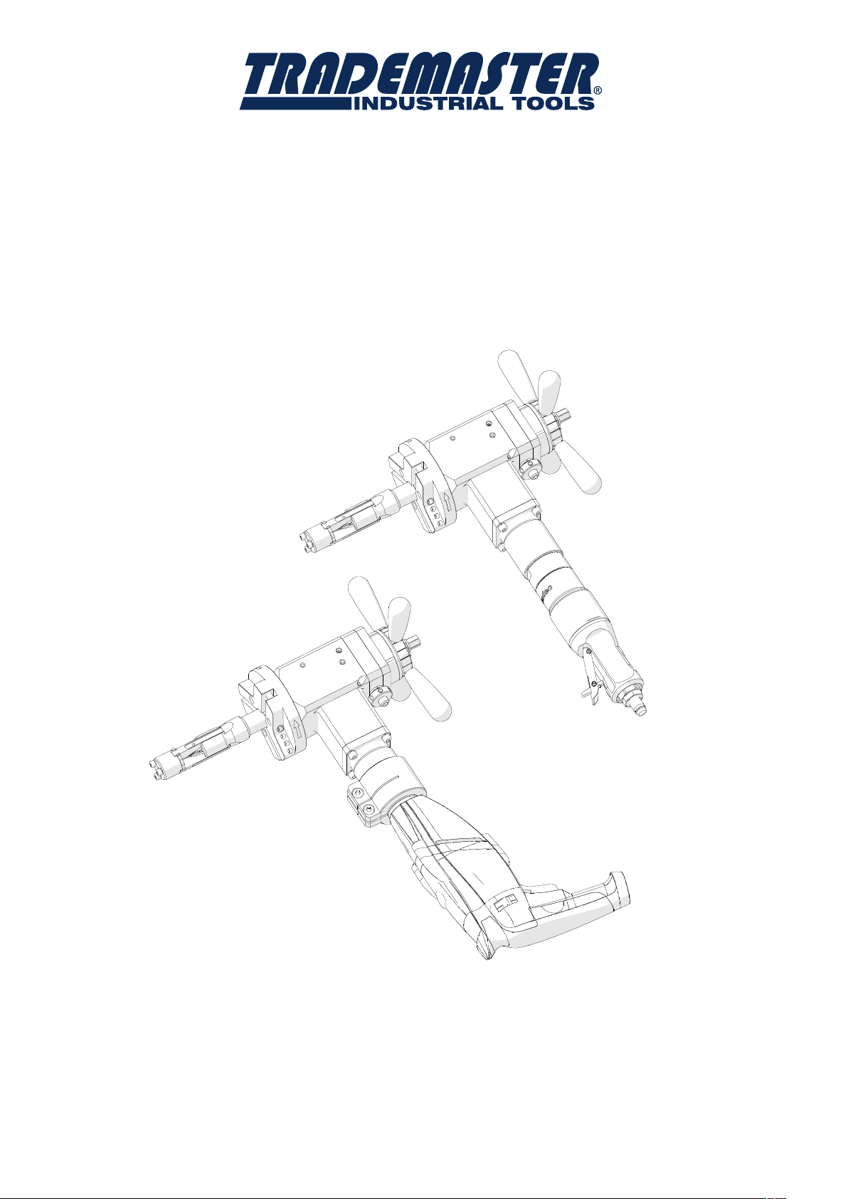
OPERATOR’S MANUAL
PRO 5 PB (PBE)
PRO 5 PB (PBE)
PIPE BEVELLING MACHINE
PRO 5 PB
PIPE BEVELLING MACHINE
OPERATOR’S MANUAL
PART# PRO5PB
BEFORE USE, ENSURE EVERYONE USING THIS MACHINE READS AND UNDERSTANDS
ALL SAFETY AND OPERATING INSTRUCTIONS IN THIS MANUAL .
Serial #............................................ Date of Purchase............................
Page 2

IMPORTED & DISTRIBUTED BY
INDUSTRIAL TOOL & MACHINERY SALES
18 BUSINESS ST
YATALA QLD 4207 AUSTRALIA
07 3287 1114
T
07 3287 1115
F
E
www.industrialtool.com.au
W
WARRANTY TERMS
In addition to any warranties or conditions implied by applicable Statute or Regulations, Industrial Tool & Machinery Sales
warrants all of it’s products against defective workmanship and faulty materials for a period of twelve (12) months from the date
of purchase, unless otherwise stated. At our option we will repair or replace, free of charge, any item on the condition that:
• The complete machine or tool is returned, freight prepaid to ITM or one of it’s authorised service agents as directed by ITM,
and is found to have a material or constructional defect.
• The machine or tool has not been subject to misuse, neglect or damage by accident.
• The fault is not a result of normal “wear and tear”.
• Written permission has been received from ITM prior to commencement of repair.
• Repairs, tampering or modification carried out by unauthorised personnel will void all warranty.
• Consumable items such as cutting tools, pilot pins, saw blades, grinding wheels etc. are NOT covered by warranty.
Our goods come with guarantees which cannot be excluded under the Australian Consumer Law. You are entitled to replacement
or refund for a major failure and to compensation for other reasonably foreseeable loss or damage. You are also entitled to have
the goods repaired or replaced if the goods fail to be of acceptable quality and the failure does not amount to a major failure.
CONTENTS
1. GENERAL INFORMATION 3
1.1. Application 3
1.2. Technical data 3
1.3. Design 5
1.4. Equipment included 5
2. SAFETY PRECAUTIONS 6
3. STARTUP AND OPERATION 8
3.1. Mounting the jaw blocks and tool bits 8
3.2. Mounting (dismounting) the mandrel and adjusting clearance 9
3.3. Mounting the motor 10
3.4. Clamping the machine into the pipe 11
3.5. Preparing air (for machine with air motor) 12
3.6. Operating 12
3.7. Troubleshooting (for machine with electric motor) 13
3.8. Replacing the spindle disk 14
3.9. Facing and bevelling at the same time 15
4. ACCESSORIES 16
4.1. Tool bits 16
4.2. Cutting fluid 18
4.3. Electric motor 18
4.4. Electric motor attachment set 18
4.5. Air motor 19
4.6. Air preparation unit 19
4.7. 75 mm spindle disk 19
4.8. 140 mm spindle disk set 20
4.9. Ratchet wrench 21
5. PARTS BREAKDOWN 22
2 PRO 5 PB USER MANUAL
Page 3
PRO 5 PB (PBE)
1. GENERAL INFORMATION
1.1. Application
The PRO 5 PB (PBE) is a pipe bevelling machine designed to mill edges of pipes
made of carbon and stainless steel, aluminum alloys, and copper-nickels. Depending
on the tool bit used, the machine can perform external bevelling, J-bevelling, internal
calibration, and facing pipes from inside diameters of 32 mm (1.26’’) to outside
diameters of 114 mm (4.49’’). Up to three tool bits can be mounted at the same time.
When equipped with an optional 140 mm spindle disk set the machine can bevel
pipes with outside diameters up to 140 mm. Using an optional 75 mm spindle disk,
ratchet wrench, or both, will facilitate working in places hard to reach.
1.2. Technical data
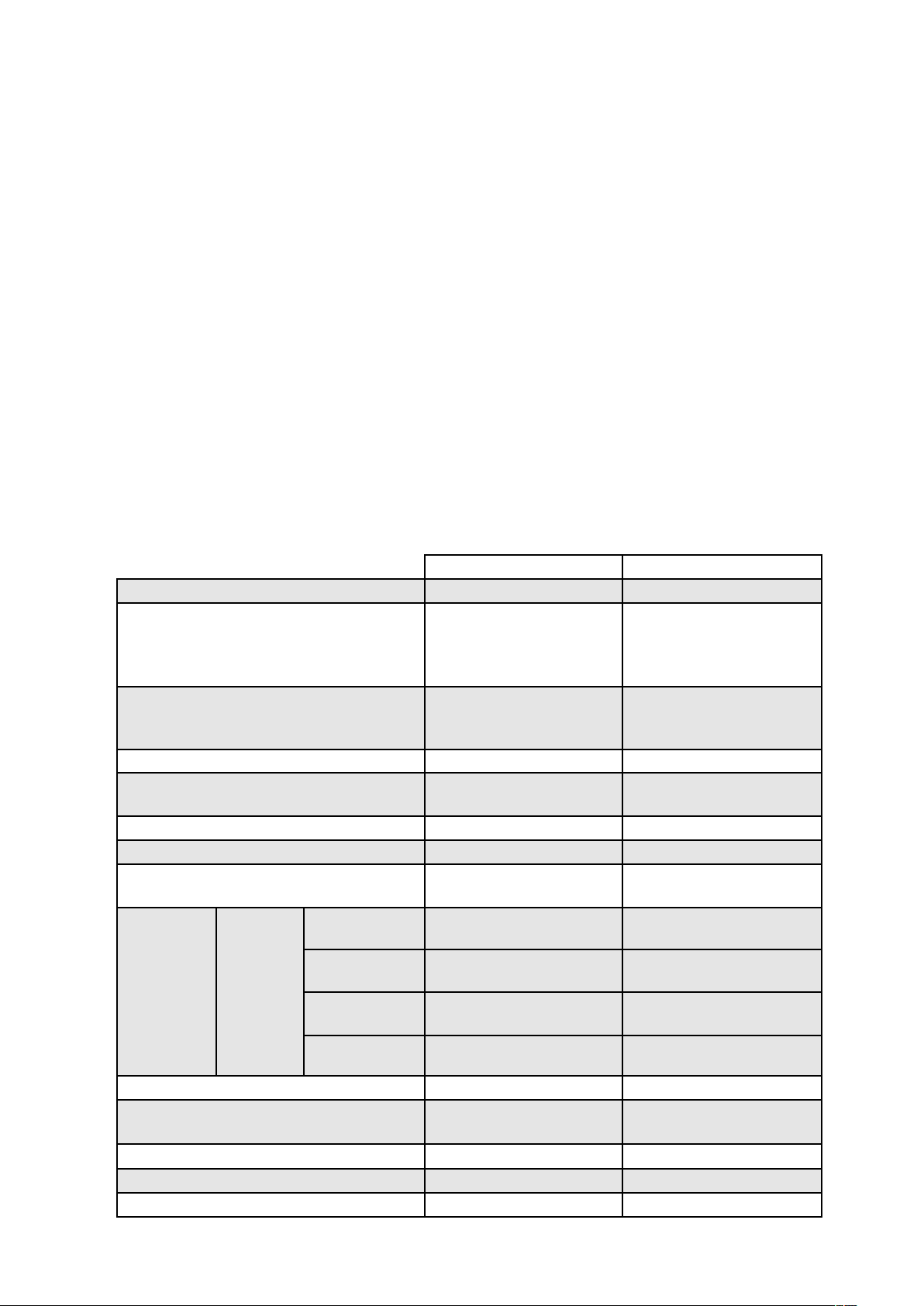
PRO 5 PB PRO 5 PBE
Pressure
Voltage –
Air motor
Electric motor – Metabo BE1100
Connection
Air consumption
Power
Pipe diameter
up
to 114
mm
Maximum
pipe wall
thickness
Rotational speed without load
Nominal rotational speed 90 rpm
Protection class – II
Required ambient temperature 0–40°C (34–104°F) 0–40°C (34–104°F)
Weight (with motor) 10 kg (22 lbs) 11 kg (24 lbs)
for
outside
diameter
114–124
mm*
124–132
mm*
132–140
mm*
0.6 MPa (87 psi) –
1~ 110–120 V, 50–60
Hz
1~ 220–240 V, 50–60
Hz
Modec
NT10RT0851FCA1FCO
CEJN 410 DN 10.4 GZ
1/2’’ BSPT coupling
1600 Nl/min (57 CFM) –
800 W 1100 W
32 mm ID to 114 mm
OD (1.26–4.49’’)
12 mm (0.47’’) 12 mm (0.47’’)
10 mm (0.39’’) 10 mm (0.39’’)
8 mm (0.31’’) 8 mm (0.31’’)
6 mm (0.24’’) 6 mm (0.24’’)
180 rpm –
–
electrical plug
32 mm ID to 114 mm
OD (1.26–4.49’’)
0–90 rpm (gear 1)
0–300 rpm (gear 2)
3PRO 5 PB USER MANUAL
Page 4
PRO 5 PB (PBE)
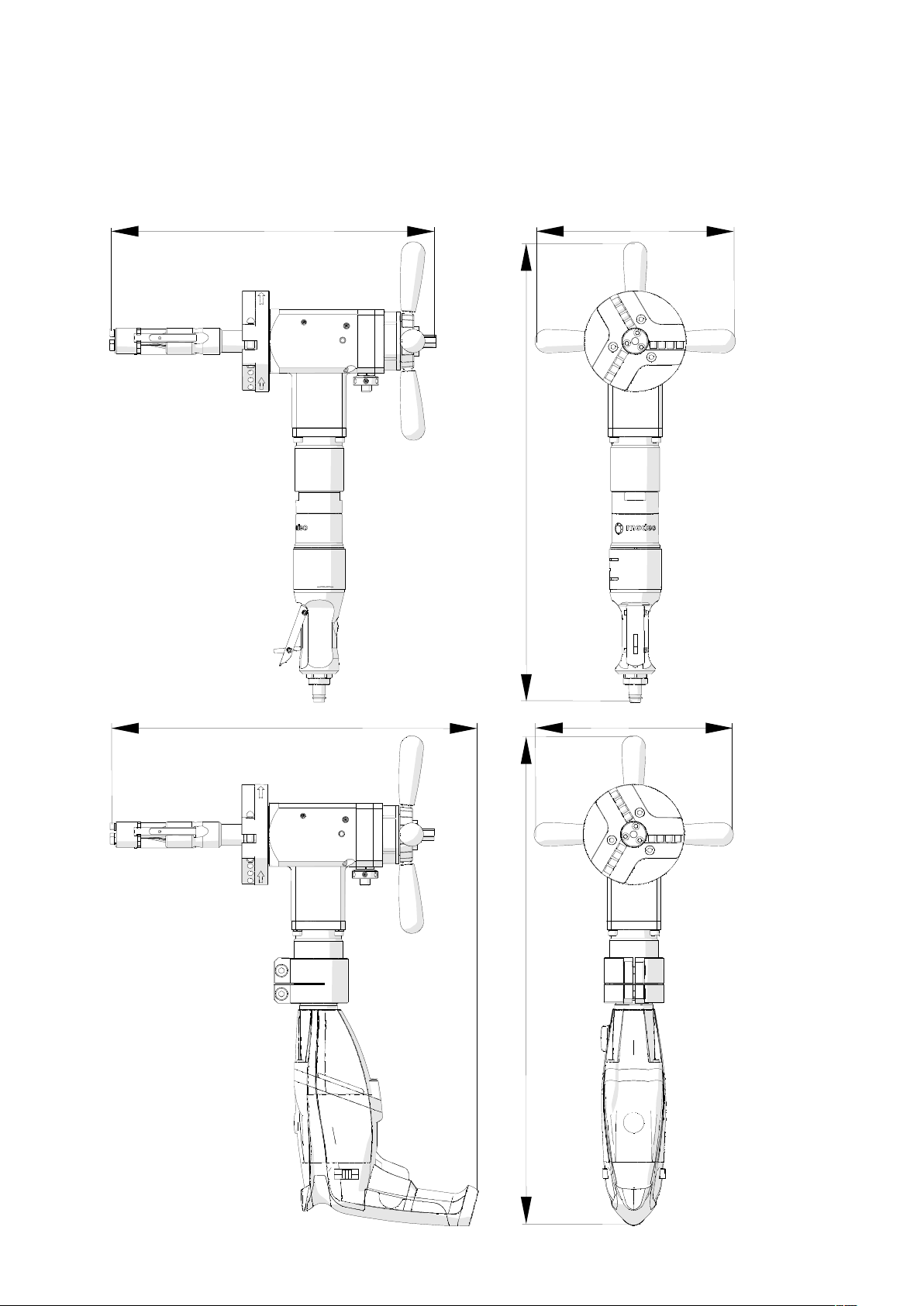
* Available with the optional 140 mm spindle disk set.
380 mm (15’’)
232 mm (9’’)
539 mm (21’’)
433 mm (17’’)
232 mm (9’’)
577 mm (23’’)
4 PRO 5 PB USER MANUAL
Page 5
PRO 5 PB (PBE)
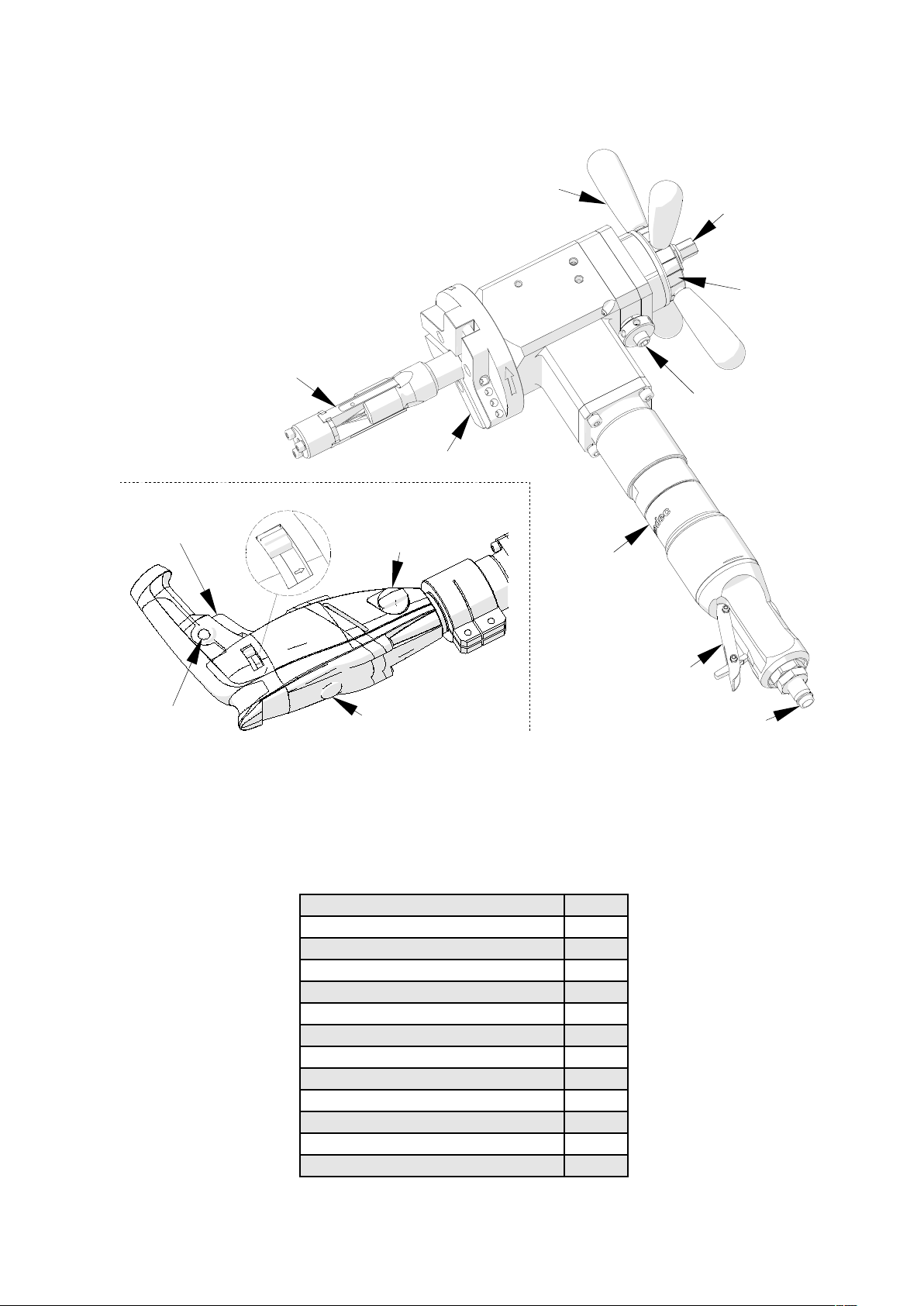
1.3. Design
Expanding mandrel
Spindle disk
Rotation direction switch (must be set as shown)
ON/OFF switch
Gear switch
Spoke handle
Draw nut
Feed
indicator
Clearance
adjustment
unit
Air motor
ON/OFF lever
ON switch lock
Speed adjustment dial
Air connection
Fig. 1. Design of PRO 5 PB and of PRO 5 PBE electric motor
1.4. Equipment included
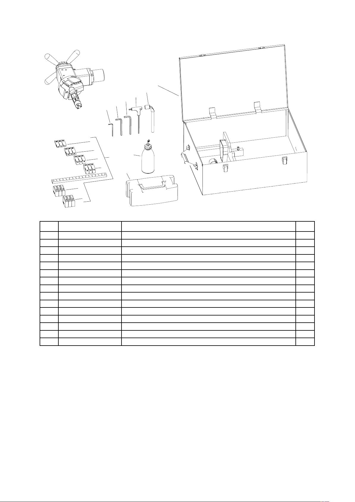
The PRO 5 PB (PBE) is supplied in a metal box with complete standard equipment.
The included equipment consists of:
Bevelling machine (without tool bits) 1 unit
Metal box 1 unit
Expanding mandrel 1 unit
118 mm spindle disk 1 unit
Jaw blocks (number 1, 2, 3, 4, 5, 6) 3 sets
Coolant container 1 unit
Tool container 1 unit
13 mm socket wrench 1 unit
6 mm hex wrench 1 unit
5 mm hex wrench 1 unit
4 mm hex wrench with handle 1 unit
3 mm hex wrench 1 unit
Operator’s Manual 1 unit
5PRO 5 PB USER MANUAL
Page 6

PRO 5 PB (PBE)
2. SAFETY PRECAUTIONS
1. Before beginning, read this Operator’s Manual and complete proper occupational
safety and health training.
2. Use only the air (electric) motor specified in the technical data.
3. The machine must be used only in applications specified in this Operator’s Manual.
4. The machine must be complete and all parts must be genuine and fully operational.
5. The supply specifications must conform to those specified on the rating plate.
6. Supply the machine with air motor only with clean and lubricated air. The air
installation must be equipped with a filter, regulator, and lubricator.
7. Never pull the hose (cord) as this may cause its damage and result in serious injury.
8. Untrained bystanders must not be present near the machine.
9. Before beginning, check the condition of the machine and air (electrical)
installation,
and tool bits.
10. Avoid unintentional starts. Do not lay the machine in such a manner that will start
including the supply hose (cord), coupling (plug), control components,
the motor and never carry the machine with air motor using the ON/OFF lever.
11. Keep the machine dry. Exposure to rain, snow, or frost is prohibited.
12. Keep the work area well lit, clean, and free of obstacles.
13. Never use the machine near flammable liquids or gases, or in explosive
environments.
14. Secure the pipe to prevent it from dropping or rolling.
15. Never use dull or damaged tool bits.
16. Use only tool bits specified in this Operator’s Manual.
17. Mount tool bits securely. Remove adjusting keys and wrenches from the work
area before connecting the machine to the supply.
18. Before every use, inspect the machine to ensure it is not damaged. Check whether
any part is cracked or improperly fitted. Make sure to maintain proper conditions
that may affect the operation of the machine.
19. Always use eye and hearing protection, protective footwear, and protective
clothing during operation. Do not wear loose clothing.
20. Operate the machine with electric motor only with the rotation direction switch in
the position shown in Fig. 1. Using left rotation (rotation direction switch set to the
opposite position) may damage the machine.
6 PRO 5 PB USER MANUAL
Page 7

PRO 5 PB (PBE)
21. Do not touch moving parts or metal chips formed during milling. Prevent objects
from being caught in moving parts.
22. After every use, remove metal chips and excess coolant from the machine.
Never remove chips with bare hands. Clean
the machine with a cotton cloth
without using any agents.
23. Cover steel parts with a thin anti-corrosion coating to protect the machine from
rust when not in use for any extended period.
24. Maintain the machine and mount/dismount parts and tool bits only with the
machine unplugged from the air (electric) installation.
25. Repair only in a service center appointed by the seller.
26. If the machine falls from any height, is wet, or has any other damage that could
affect the technical state of the machine, stop the operation and immediately
send the machine to the service center for inspection and repair.
27. Never leave the machine unattended during operation.
28. Remove from the worksite and store in a secure and dry location when not in
use, previously removing the tool bits from sockets.
7PRO 5 PB USER MANUAL
Page 8
PRO 5 PB (PBE)
3. STARTUP AND OPERATION
All safety precautions must be closely observed.
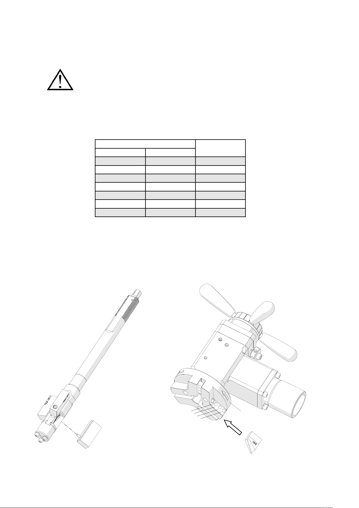
3.1. Mounting the jaw blocks and tool bits
Use the following table to select jaw blocks suitable to the diameter of the pipe to be
machined.
Pipe inside diameter
[mm] [inch]
32–43.5 1.26–1.71 –
43–55 1.69–2.17 1
54–66.2 2.13–2.61 2
64.7–76.9 2.55–3.03 3
74.9–87.1 2.95–3.43 4
85.2–97.4 3.35–3.83 5
94.8–107
3.73–4.21 6
Jaw blocks
number
Use the 3 mm hex wrench to join the jaw blocks to the expanding mandrel (1,
Fig. 2). Then, select up to three tool bits suitable to planned use, and place them in
the sockets, with blades directed according to the rotation direction 2. Next, tighten
each tool bit with two of the screws 3 using the 4 mm hex wrench. The entire pressing
surface of the screw must be in full contact with the tool bit.
3
1
Fig. 2. Mounting the jaw blocks and tool bits
8 PRO 5 PB USER MANUAL
2
Page 9
PRO 5 PB (PBE)
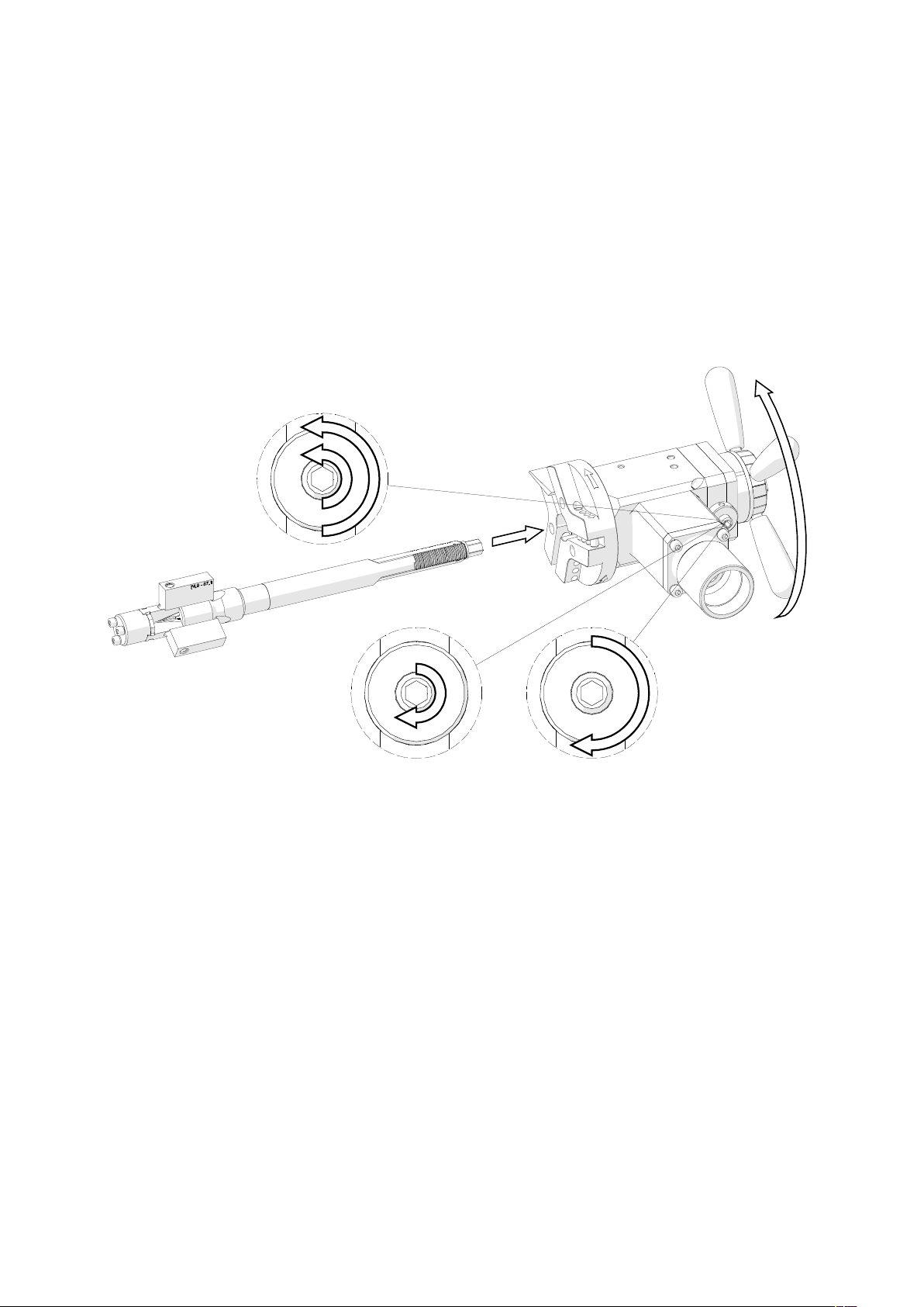
3.2. Mounting (dismounting) the mandrel and adjusting clearance
Loosen the nut and use the 6 mm hex wrench to loosen the set screw (1, Fig. 3), and
insert the mandrel into the machine (2). Make sure that tool bits installed are not in
contact with the mandrel. Then, rotate the spoke handles clockwise (3) by at least 10
turns until the mandrel engages with the machine completely. Then, tighten the set
screw (4) and check whether the spoke handles can be rotated in both directions
easily. If the screw is too tight, readjust it. Finally, tighten the lock nut (5).
33
1
2
4
Fig. 3. Mounting the mandrel into the machine
5
If the expanding mandrel becomes loose causing vibrations of the tool bits during
machining, perform the above actions without removing the mandrel from the machine.
To dismount the mandrel, loosen the nut and use the 6 mm hex wrench to
loosen the set screw (1, Fig. 3) to at least one turn. Then, rotate the spoke handles
counterclockwise to disengage the mandrel from the machine.
9PRO 5 PB USER MANUAL
Page 10
PRO 5 PB (PBE)
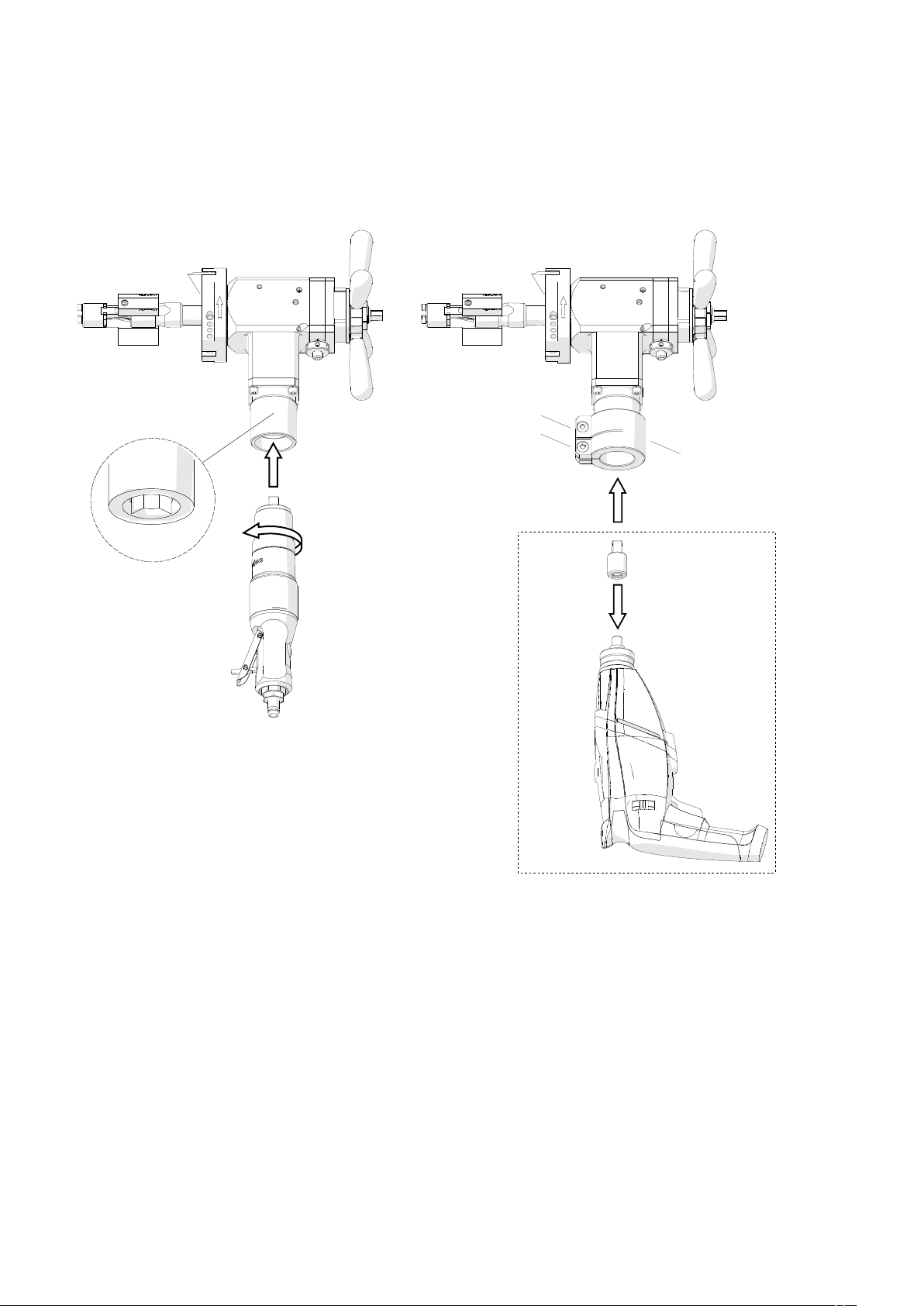
3.3. Mounting the motor
Insert the air motor into the machine (1, Fig. 4a) in such a way to place the arbor in
the socket 2, and tighten the motor by rotating it counterclockwise (3).
a) b)
2
1
3
7
5
6
5
4
5
Fig. 4. Mounting the air motor (a) and the electric motor (b)
To mount the electric motor, slide the clamping ring 4 onto the machine. Then,
screw the driver (5) into the motor and insert the motor into the machine (6) by placing
the arbor in the socket 2, and tighten the clamping ring using the 6 mm hex wrench (7).
Finally, set the rotation direction switch to the position shown in Fig. 1.
10 PRO 5 PB USER MANUAL
Page 11
PRO 5 PB (PBE)
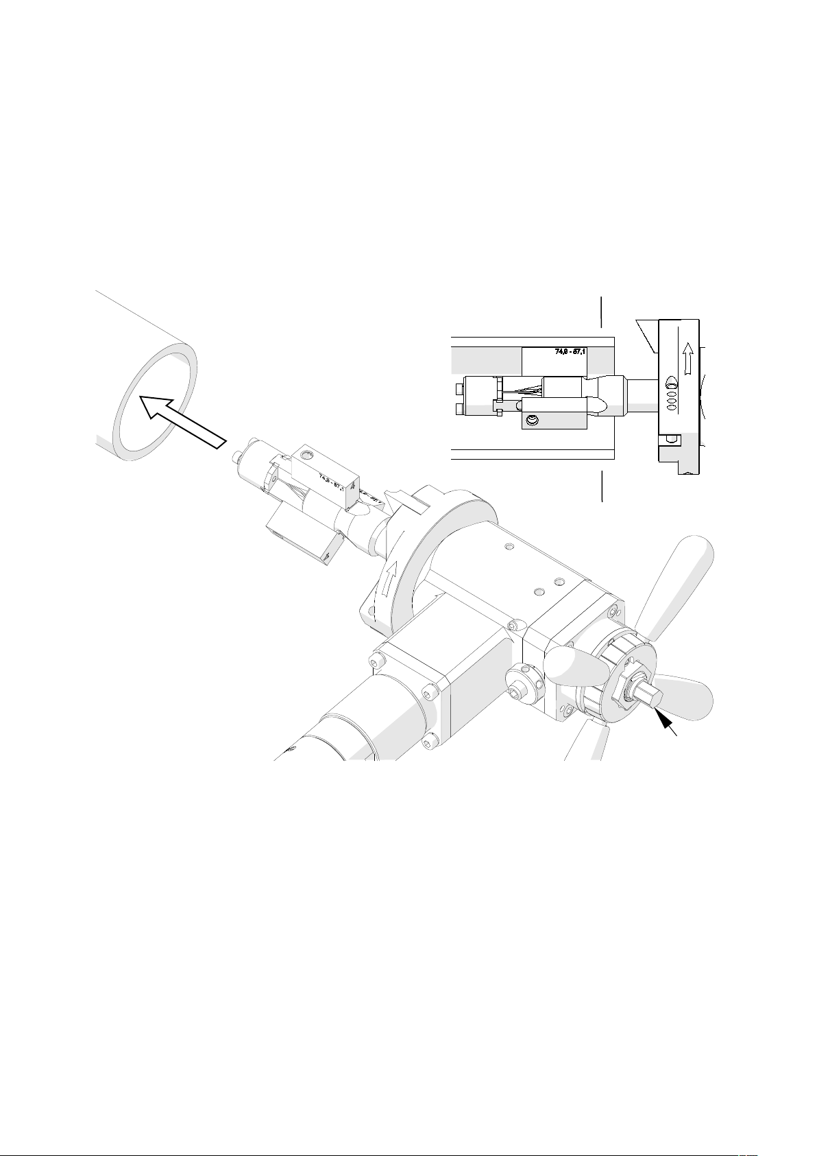
3.4. Clamping the machine into the pipe
Insert the assembled machine into the pipe (1, Fig. 5) in such a way to place the tool
bit(s) at the distance of at least 3 mm (0.12’’) from the pipe end. Then, expand the
jaw blocks to the inside diameter of the pipe by rotating the draw nut 2 clockwise
using the 13 mm socket wrench. The jaw blocks must be installed beyond the end
preparation location 3.
3
1
3
Fig. 5. Clamping the machine into the pipe
2
11PRO 5 PB USER MANUAL
Page 12
PRO 5 PB (PBE)
3.5. Preparing air (for machine with air motor)
Connect the machine to a correctly prepared air supply of sufficient purity using
a hose with the internal diameter of at least 12 mm (0.5’’). The air installation must be
equipped with an air preparation unit: filter, regulator, and lubricator (FRL). To
achieve full power of the air motor, all internal diameters of the air installation must
be at least 10 mm (0.4’’).
Maintain the FRL unit as required to keep the water trap drained, filter cleaned,
and the lubricator oil reservoir filled so that there is a drop of oil every 2–5 seconds.
Use only oil which ignition temperature exceeds 260°C (500°F). If the machine is to
be left idle for at least 24 hours, increase the delivery of oil and run the motor for 2–3
seconds, which will prevent rusting and degrading of the rotor vanes.
3.6. Operating
Once the machine is connected to a proper supply, start the operation by pressing
the ON/OFF lever. For the machine with electric motor, select gear 1 and set the
maximum speed, then press and hold the ON/OFF switch. To lock the switch in
position ON, press the ON switch lock before releasing the ON/OFF switch.
Spread the coolant on the working edge. Then, bring the tool bit(s) close to the
pipe by rotating the spoke handles clockwise. If the pipe face is not perpendicular to
the pipe axis, the tool bit will machine only a small segment of the pipe during initial
rotations. Thus, the feed rate should be chosen slow until the tool bit is contacting the
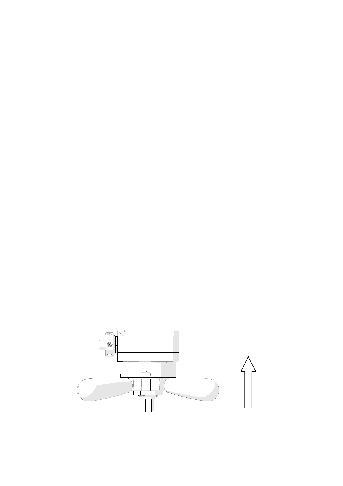
pipe continually during at least one rotation. The axial feed is 0.11 mm (0.004’’) per
graduation (Fig. 6) or 2 mm (0.08’’) per one complete turn of the spoke handles.
feed direction
0.11 mm (0.004’’)
Fig. 6. View of the feed indicator
12 PRO 5 PB USER MANUAL
Page 13

PRO 5 PB (PBE)
Continue machining by rotating the spoke handles clockwise. Use adequate feed
rate to establish a continuous chip cut. If the feed rate is too slow, only light stringer
chips will be removed, while too fast feed will make machining difficult and the chip
will start to have a rough or torn appearance. Never allow the tool bit to burnish the
surface. If chatter problems occur, reduce the feed rate and speed, and make sure
the type of tool bits corresponds to the material and the tool bits are sharp. Stainless
steel, which work hardens, must be worked with a fast enough feed, 0.08–0.15 mm
(0.003–0.006’’) per rotation, to stay under the work hardened surface.
If the machine with electric motor becomes overloaded, the motor will be shut off
automatically. However, prevent the motor from overloading by machining hard
materials with not too fast feed rate and rotational speed, if possible.
Once the pipe end is machined completely, discontinue rotating the spoke handles
and allow the spindle to rotate several more turns to improve the finish of the surface.
Then, turn off the motor by releasing the ON/OFF lever, or press the ON/OFF switch
in the machine with electric motor, and wait until the rotation stops. Separate the tool
bit(s) from the pipe end to at least 3 mm (0.12’’) by rotating the spoke handles
counterclockwise. Finally, loosen the draw nut using the 13 mm socket wrench to
release the clamping, and remove the machine from the pipe. Use petroleum ether
to clean the pipe from excess coolant.
Clean the machine with a cotton cloth without using any agents.
3.7. Troubleshooting (for machine with electric motor)
The machine with electric motor has a diode for troubleshooting. The diode
permanently lit means limited machine power to prevent the motor from overheating
as a result of continuous overloading for extended periods.
Rapid flashing means that the safety circuit prevents the machine from starting
automatically when electrical power is restored after a power failure. To start the
machine is such a case, switch the motor off and on again.
Slow flashing means the carbon brushes are almost completely worn, which
results in the motor shutting off automatically. The brushes must be replaced with
new ones by the manufacturer of the electric motor.
13PRO 5 PB USER MANUAL
Page 14
PRO 5 PB (PBE)
3.8. Replacing the spindle disk
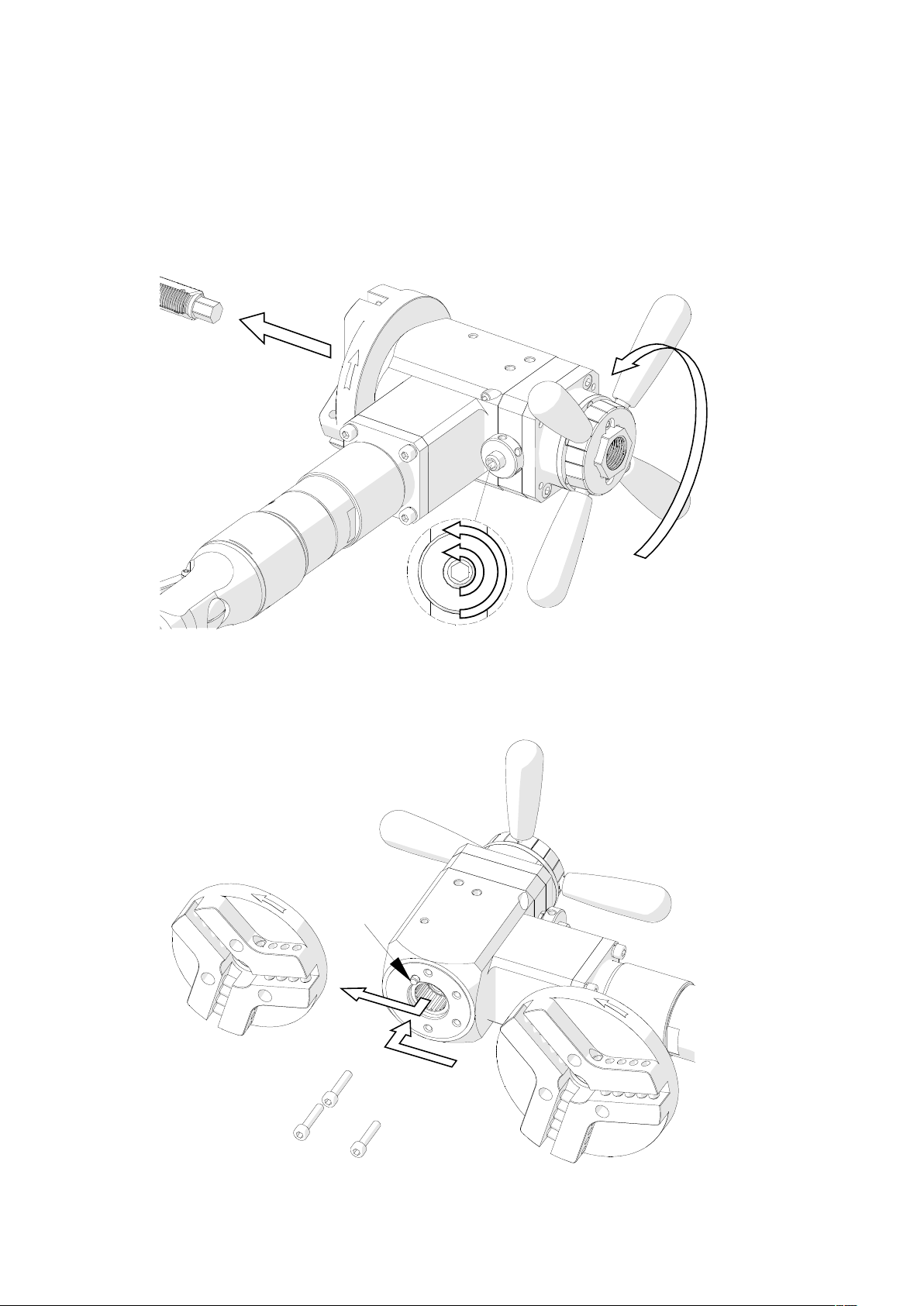
Loosen the nut and use the 6 mm hex wrench to loosen the set screw (1, Fig. 7) to at
least one turn. Then, rotate the spoke handles counterclockwise (2) to disengage the
mandrel from the machine (3).
3
2
1
Fig. 7. Removing the mandrel from the machine
Use the 5 mm hex wrench (1, Fig. 8) and remove the spindle disk (2). Then, mount
the new disk (3) onto the pin 4 and tighten with the same screws.
4
2
3
1
Fig. 8. Replacing the spindle disk
14 PRO 5 PB USER MANUAL
Page 15
PRO 5 PB (PBE)
3.9. Facing and bevelling at the same time
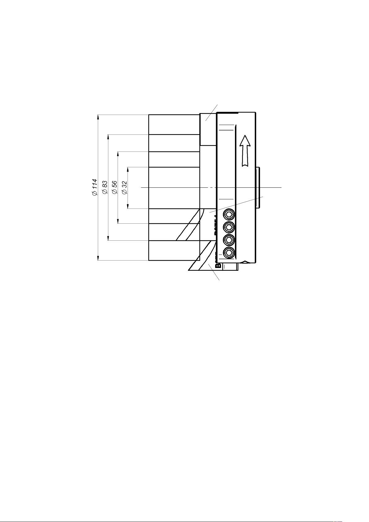
When facing and bevelling is performed at the same time, use either short or long
bevelling tool bit depending on the pipe diameter (Fig. 9).
F0-30 facing tool bit
Short tool bit
Short or long
tool bit
Long tool bit
Long tool bit
Long tool bit
Short or long
tool bit
Short tool bit
Short tool bit
Fig. 9. Positioning the facing tool bit and a short or long bevelling tool bit
15PRO 5 PB USER MANUAL
Page 16
PRO 5 PB (PBE)
4. ACCESSORIES
4.1. Tool bits
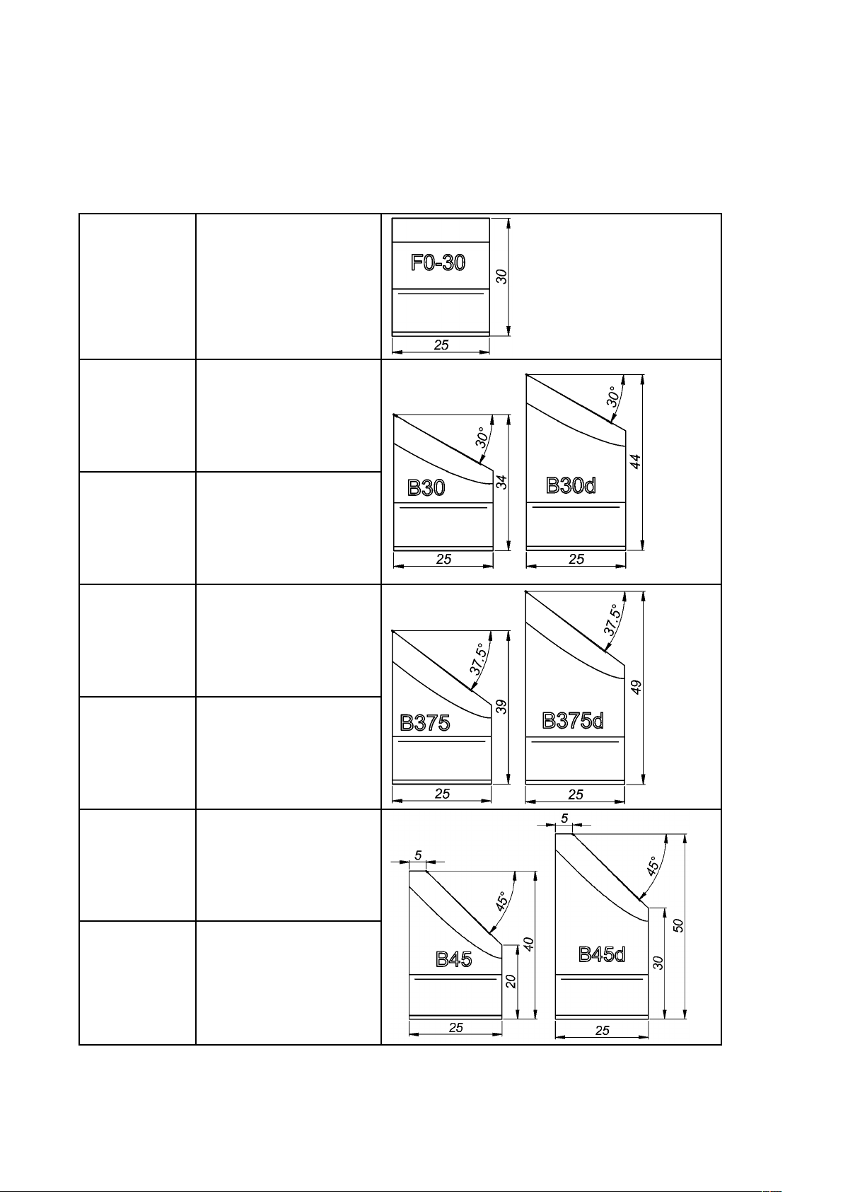
WAP-P05/F030
WAP-P05/B3034
WAP-P05/B3044
WAPP05/B37539
F0-30
0° facing tool bit
B30
30° bevelling tool bit*
B30d
30° bevelling tool bit**
B375
37.5° bevelling tool bit*
WAPP05/B37549
WAP-P05/B4540
WAP-P05/B4550
* for diameters over 56 mm, if works together with 0° facing tool bit
** for diameters under 83 mm, if works together with 0° facing tool bit
B375d
37.5° bevelling tool bit**
B45
45° bevelling tool bit*
B45d
45° bevelling tool bit**
16 PRO 5 PB USER MANUAL
Page 17
PRO 5 PB (PBE)
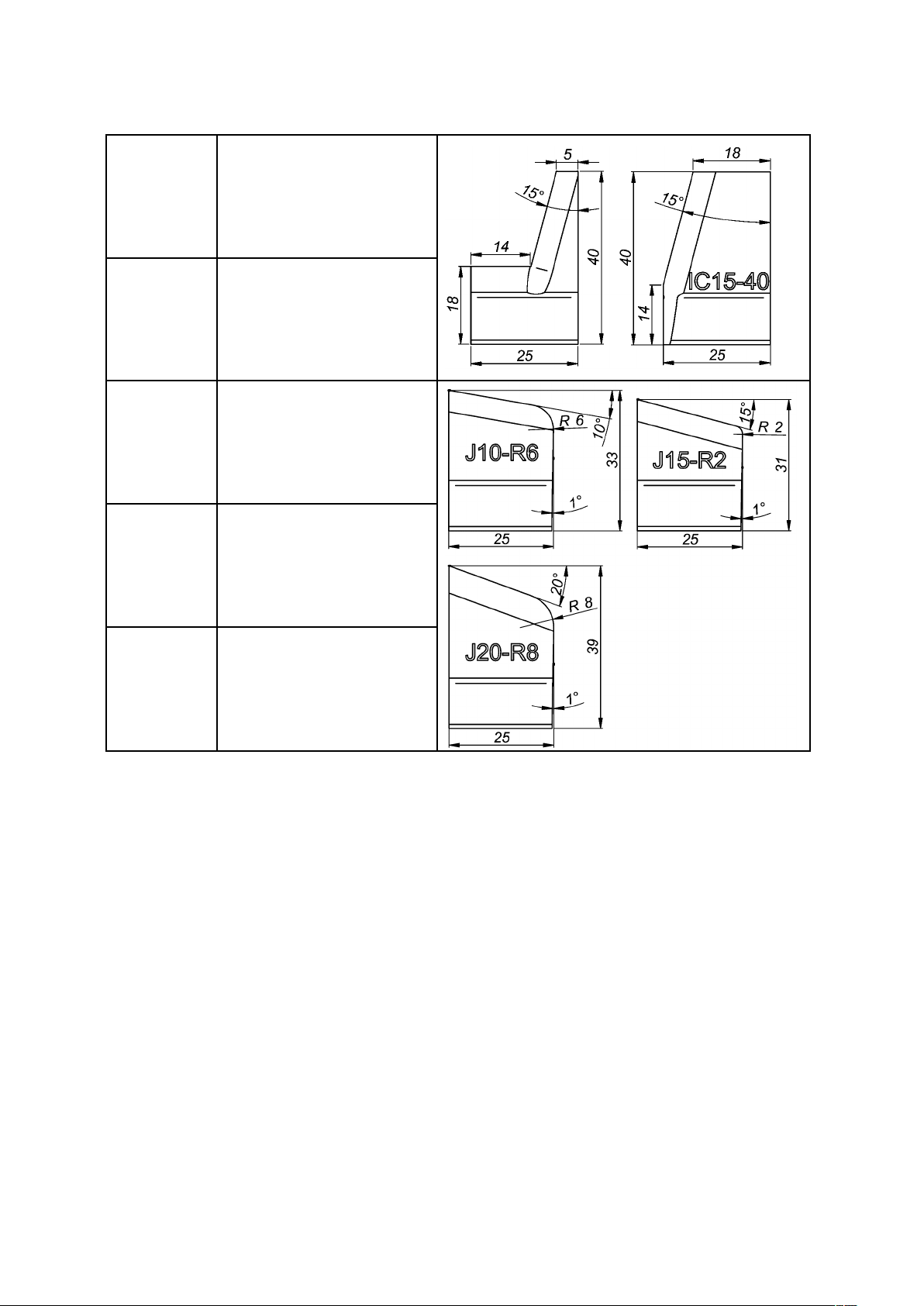
WAPP05/IB1540
WAPP05/IC1540
IC15-40
15° internal calibration tool
bit
IC15-40
(for diameters over 56 mm)
15° internal calibration tool
bit
WAPP05/J2533R6
WAPP05/J2531R2
WAPP05/J2539R8
J10-R6
10° J-bevelling tool bit
J15-R2
15° J-bevelling tool bit
J20-R8
20° J-bevelling tool bit
17PRO 5 PB USER MANUAL
Page 18
PRO 5 PB (PBE)
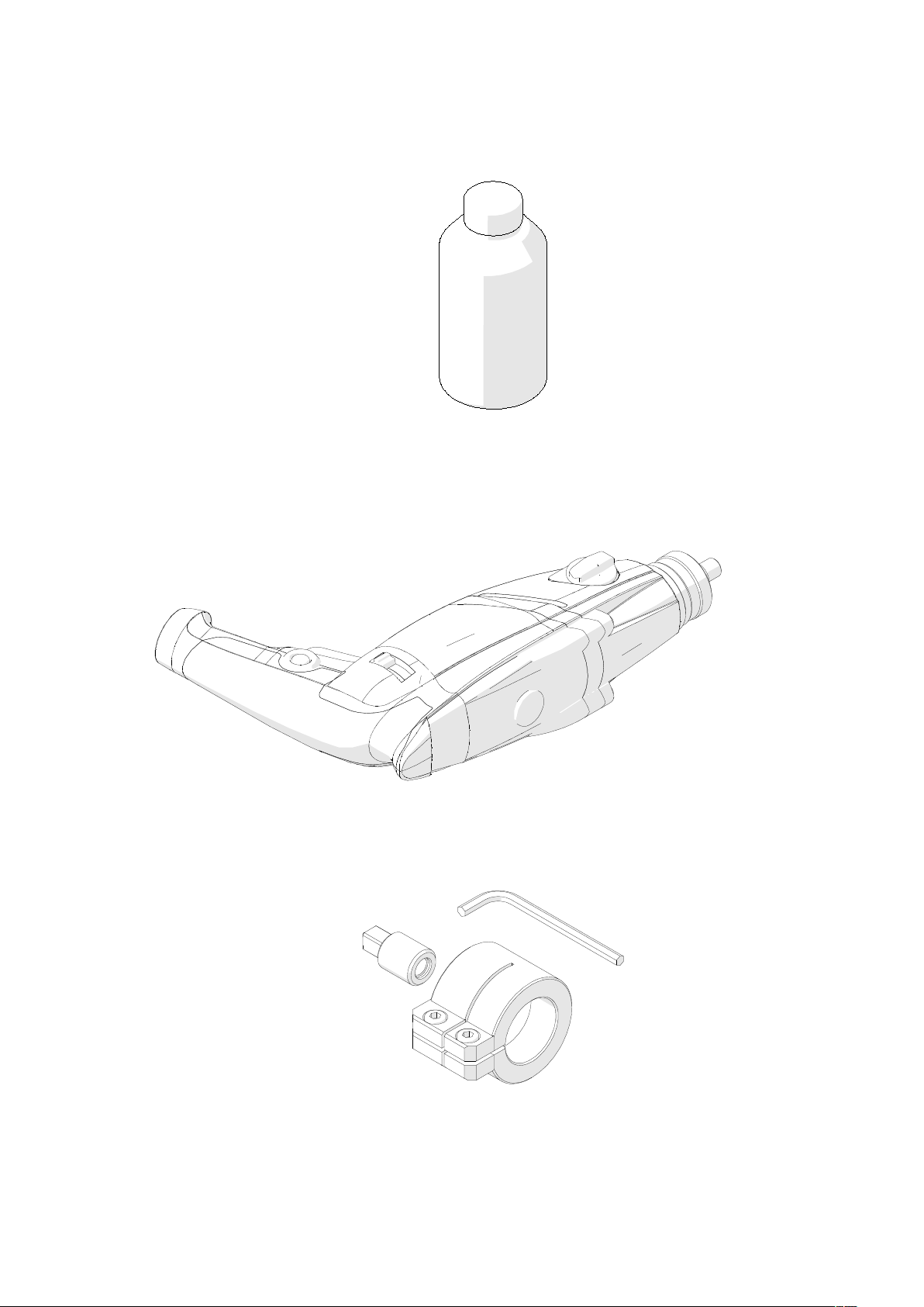
4.2. Cutting fluid
4.3. Electric motor
Part number:
WAP-B05/105
4.4. Electric motor attachment set
Required for connecting the electric motor with the machine.
Part number:
WAP-B05130
18 PRO 5 PB USER MANUAL
Page 19
PRO 5 PB (PBE)
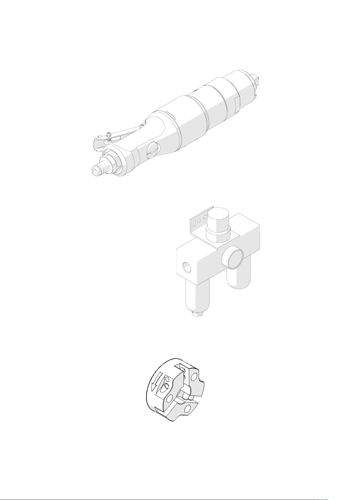
4.5. Air motor
Part number:
WAP-B05/100
4.6. Air preparation unit
ffilter, regulator, lubricator
4.7. 75 mm spindle disk
Facilitates working in places hard to reach.
Part number:
WAP-B05/140
19PRO 5 PB USER MANUAL
Page 20
PRO 5 PB (PBE)
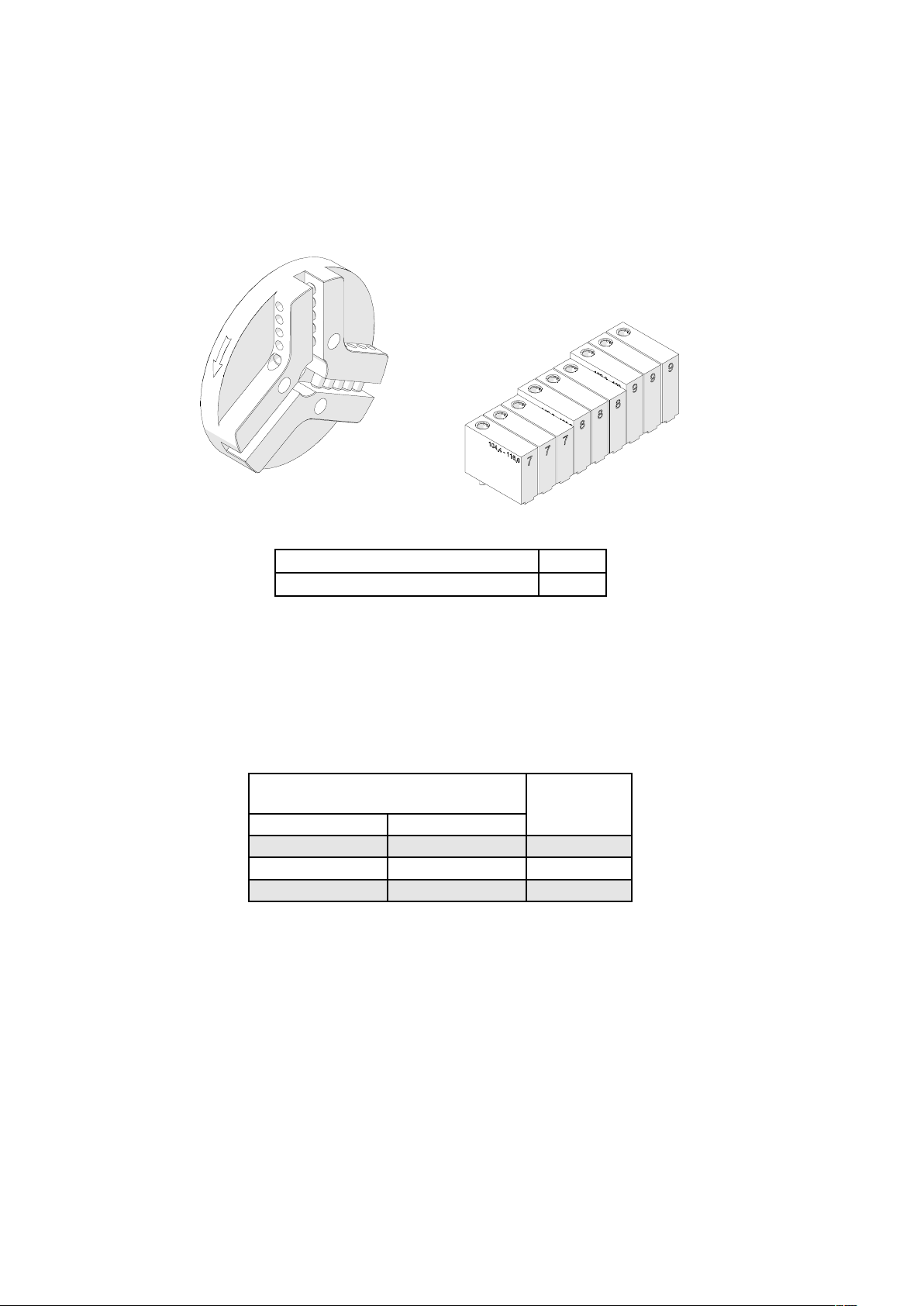
4.8. 140 mm spindle disk set
Allows machining pipes from inside diameters of 105 mm (4.13’’) to outside
diameters of 140 mm (5.51’’).
Part number:
WAP-B05/130
Included equipment consists of:
140 mm spindle disk 1 unit
Jaw blocks (number 7, 8, 9) 3 sets
Install the spindle disk after previously removing the existing spindle disk (Fig. 7,
Fig. 8). Then, use the following table to select jaw blocks of the set suitable to the
inside diameter of the pipe to be machined, and use the 3 mm hex wrench to tighten
them to the expanding mandrel (1, Fig. 2). Mount the tool bits in the sockets and
tighten the screws (3, Fig. 2) using the 4 mm hex wrench.
Pipe inside diameter
with 140 mm spindle disk set
[mm] [inch]
104.4–116.6 4.11–4.59 7
113.6–125.8 4.47–4.95 8
122.8–133
4.83–5.24 9
Jaw block
number
20 PRO 5 PB USER MANUAL
Page 21
PRO 5 PB (PBE)
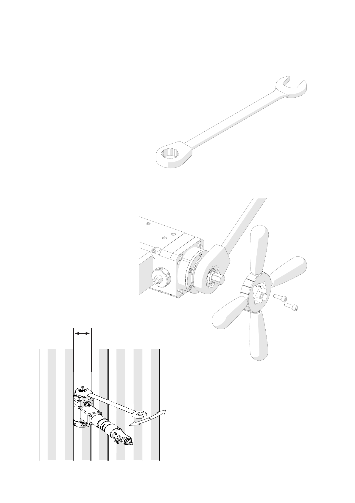
4.9. Ratchet wrench
Allows performing the feed instead of the spoke handles.
To dismount the feed disk and use the ratchet wrench, unscrew two screws using
the 4 mm hex wrench.
75MM
75 mm
(2.95’’)
21PRO 5 PB USER MANUAL
Page 22
Parts list PRO-5PB v.1.04
5.0. PARTS BREAKDOWN
ITEM PART NUMBER DESCRIPTION Q-TY
1 WAP-B05/101 JAW BLOCKS SET 1
2 WAP-B05/102 TOOL CONTAINER 1
3 WAP-B05/103 METAL BOX 1
4 WAP-B05/104 3 MM HEX WRENCH 1
5 WAP-B05/105 5 MM HEX WRENCH 1
6 WAP-B05/106 6 MM HEX WRENCH 1
7 WAP-B05/107 4 MM HEX WRENCH WITH HANDLE 1
8 WAP-B05/108 SOCKET WRENCH s=13 1
9 WAP-B05/109 COOLANT CONTAINER 1
10 WAP-B05/110 BLOCK SET L=7,4 1
11 WAP-B05/111 BLOCK SET L=13 1
12 WAP-B05/112 BLOCK SET L=18,4 1
13 WAP-B05/113 BLOCK SET L=23,5 1
14 WAP-B05/114 BLOCK SET L=28,6 1
15 WAP-B05/115 BLOCK SET L=33,4 1
3
7
9
6
5
4
12
13
1
14
15
11
10
8
2
22 PRO 5 PB USER MANUAL
Page 23
Parts list PRO-5PB v.1.04
1
36
35
8
37
43
42
38
25
39
40
2
29
41
28
23
22
15
14
26
11
13
12
10
19
16
21
33
32
34
30
3
31
6
9
4
7
5
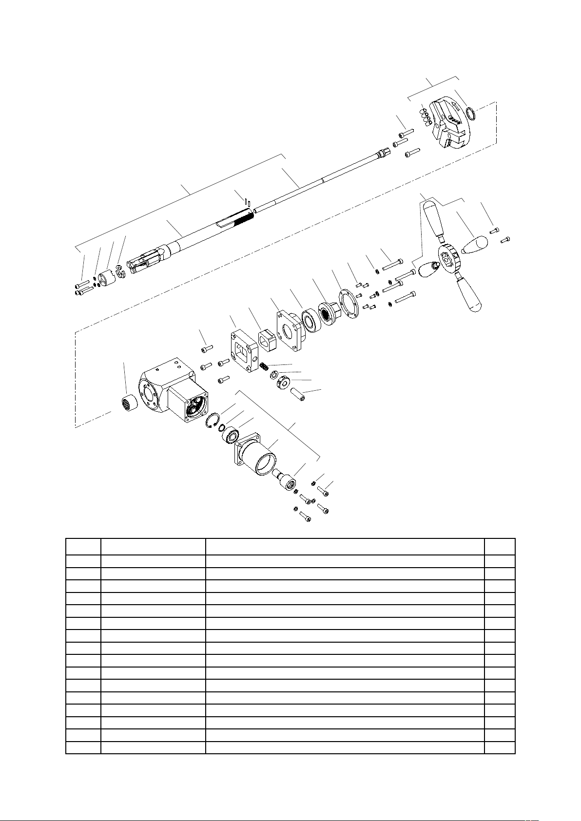
ITEM PART NUMBER DESCRIPTION Q-TY
1 WAP-B05/201 SPINDLE DISK ASSY 1
2 WAP-B05/202 EXPANDING MANDREL ASSY 1
3 WAP-B05/203 DRIVER BODY ASSY 1
4 WAP-B05/204 NUT DISK ASSY 1
5 WAP-B05/205 LEVER 4
6 WAP-B05/206 SPRING WASHER 6.1 4
7 WAP-B05/207 HEX SOCKET HEAD CAP SCREW M5x16 2
8 WAP-B05/208 HEX SOCKET HEAD CAP SCREW M6x30 3
9 WAP-B05/209 HEX SOCKET HEAD CAP SCREW M6x25 4
10 WAP-B05/210 SPRING 1
11* WAP-B05/211 DRIVE HOUSING 1
12* WAP-B05/212 LOCKING CLASP 1
13* WAP-B05/213 DRIVER CLASP 1
14* WAP-B05/214 DRAW NUT 1
15* WAP-B05/215 LOCKING RING 1
16 WAP-B05/216 KNURLED NUT 1
23PRO 5 PB USER MANUAL
Page 24

Parts list PRO-5PB v.1.04
ITEM PART NUMBER DESCRIPTION Q-TY
17 WAP-B05/217 BEARING NUT KM-7 M35x1,5 1
18 WAP-B05/218 INTERNAL RETAINING RING 62w 1
19 WAP-B05/219 SPRING WASHER 12.2 1
20 WAP-B05/220 BEARING TOOTHED WASHER MB-7 1
21 WAP-B05/221 HEX SOCKET SET SCREW WITH FLAT POINT M12x1,25x40 1
22* WAP-B05/222 SLOTTED PAN HEAD SCREW WITH SMALL HEAD M5x10 6
23* WAP-B05/223 SPRING WASHER 6.1 4
24 WAP-B05/224 HEX SOCKET SET SCREW WITH CONE POINT M8x20 1
25 WAP-B05/225 NEEDLE BEARING 25x32x20 1
26* WAP-B05/226 BALL BEARING 25x52x15 1
27 WAP-B05/227 ANGULAR BALL BEARING 35x62x14 1
28* WAP-B05/228 HEX SOCKET HEAD CAP SCREW M6x45 4
29* WAP-B05/229 HEX SOCKET HEAD CAP SCREW M6x20 4
30 WAP-B05/230 DRIVE HOUSING 1
31 WAP-B05/231 DRIVER SHAFT 1
32 WAP-B05/232 EXTERNAL RETAINING RING 15z 1
33 WAP-B05/233 INTERNAL RETAINING RING 35w 1
34 WAP-B05/234 DOUBLE-ROW ANGULAR BALL BEARING 15x35x15.9 1
35 WAP-B05/235 HEX SOCKET SET SCREW WITH FLAT POINT M8x20 12
36 WAP-B05/236 SEAL O-RING 25.2x3 1
37 WAP-B05/237 MANDREL SCREW 1
38 WAP-B05/238 NUT 1
39 WAP-B05/239 MANDREL PLATE 3
40 WAP-B05/240 MANDREL WITH JAWS ASSY 1
41 WAP-B05/241 DOWEL PIN 3n6x14 2
42 WAP-B05/242 SPRING WASHER 5.1 3
43 WAP-B05/243 HEX SOCKET HEAD CAP SCREW M5x30 3
*- MOUNTED ON MANDREL SHAFT, ITEM 2
24 PRO 5 PB USER MANUAL
 Loading...