

Page 1
GECKO
WELDING CARRIAGE
OPERATOR’S MANUAL
BEFORE USE, ENSURE EVERYONE USING THIS MACHINE READS AND UNDERSTANDS
ALL SAFETY AND OPERATING INSTRUCTIONS IN THIS MANUAL .
Serial #............................................ Date of Purchase............................
Page 2

TRADEMASTER GECKO WELDING CARRIAGE
IMPORTED & DISTRIBUTED BY
18 BUSINESS ST
YATALA QLD 4207 AUSTRALIA
07 3287 1114
T
07 3287 1115
F
E
www.industrialtool.com.au
W
INDUSTRIAL TOOL & MACHINERY SALES
WARRANTY TERMS
In addition to any warranties or conditions implied by applicable Statute or Regulations, Industrial Tool & Machinery
Sales warrants all of it’s products against defective workmanship and faulty materials for a period of twelve (12)
months from the date of purchase, unless otherwise stated. At our option we will repair or replace, free of charge,
any item on the condition that:
• The complete machine or tool is returned, freight prepaid to ITM or one of it’s authorised service agents as
directed by ITM, and is found to have a material or constructional defect.
• The machine or tool has not been subject to misuse, neglect or damage by accident.
• The fault is not a result of normal “wear and tear”.
• Written permission has been received from ITM prior to commencement of repair.
• Repairs, tampering or modification carried out by unauthorised personnel will void all warranty.
• Consumable items such as cutting tools, pilot pins, saw blades, grinding wheels etc. are NOT covered by
warranty.
Our goods come with guarantees which cannot be excluded under the Australian Consumer Law. You are entitled
to replacement or refund for a major failure and to compensation for other reasonably foreseeable loss or damage.
You are also entitled to have the goods repaired or replaced if the goods fail to be of acceptable quality and the
failure does not amount to a major failure.
TABLE OF CONTENTS
General Information 2
Technical Data 3
Design 4 - 5
Saftey Precautions 6 - 7
Startup and Operation 8 - 11
Wiring Diagram 12
Parts Lists & Exploded Views
General Assembly 13 - 14
Drive System Assembly 15
Drive System 16 - 17
Controller Housing Complete 18
Panel Assembly 19
Torch Holding & Low Torch Holding Assembly 20
1
Page 3
GENERAL INFORMATION
1. GENERAL INFORMATION
1.1. Application
The GECKO Welding Carriage produces continuous welds using MIG/MAG welding torches with
handle diameter in 16–22 mm range (0.63–0.87’’). The machine can work in PA, PB, PC, and PF
welding positions. It is fixed by permanent magnets and contains a four wheel drive with speed
adjustment.
1.2. Technical data
2
Page 4
TECHNICAL DATA
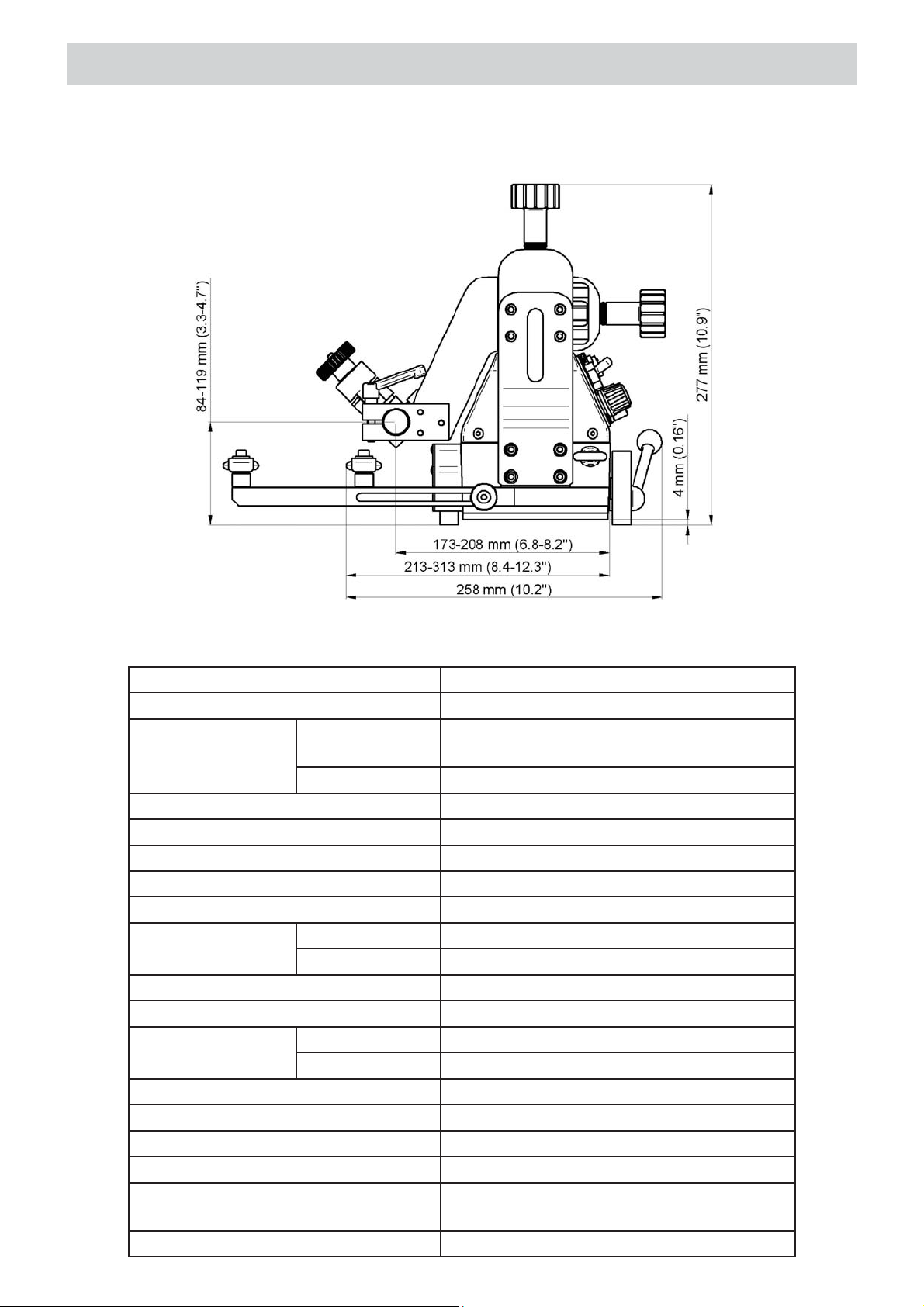
Welding position ~ 115–230 V, 50–60 Hz
Power 20 W
Welding position horizontal PA (flat), PB (horizontal vertical), PC
(horizontal)
vertical PF (vertical up)
Minimum path convex radius 1000 mm (40’’)
Minimum path concave radius 1250 mm (50’’)
Torch type MIG/MAG
Torch diameter 16–22 mm (0.63–0.87’’)
Maximum torch reach 70 mm (2.76’’)
Maximum weight
of cables
Welding material thickness minimum 4 mm (0.16’’)
Ground clearance 4 mm (0.16’’)
Pulling force horizontal work 150 N
Torch adjustment range 35 mm (1.38’’, up-down, left-right)
Follower arm adjustment range 100 mm (3.93’’)
Horizontal speed 0–110 cm/min (0–43.3’’/min)
Vertical speed 0–100 cm/min (0–39.4’’/min)
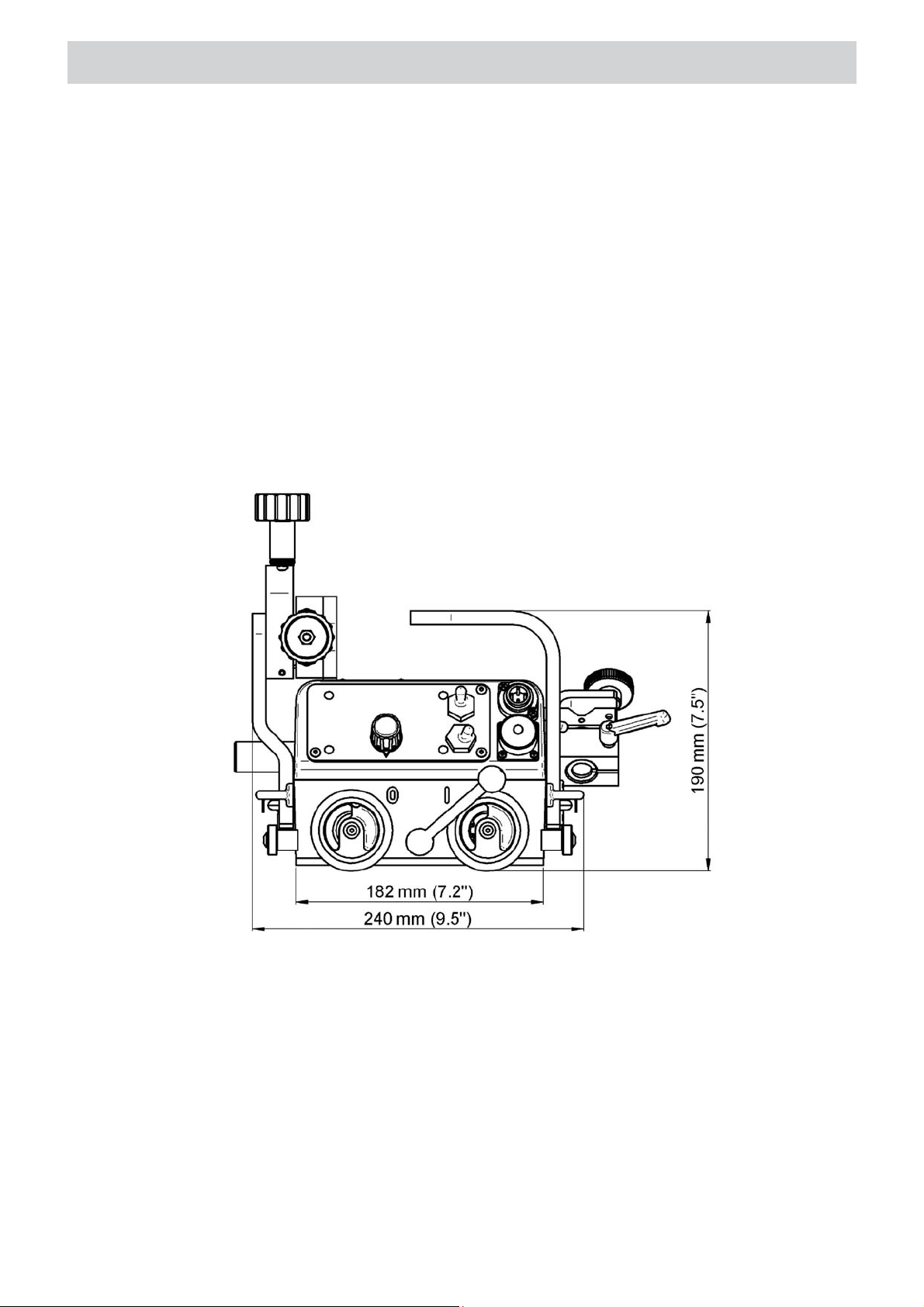
Dimensions 240 mm (L) × 258 mm (W) × 277 mm (H)
3
Weight 8 kg (17.7 lbs)
horizontal work 8 kg (17.7 lbs)
vertical work 13.3 lbs)
vertical work 100 N
9.5’’ (L) × 10.2’’ (W) × 10.9’’ (H)
Page 5
DESIGN
1.3. Design
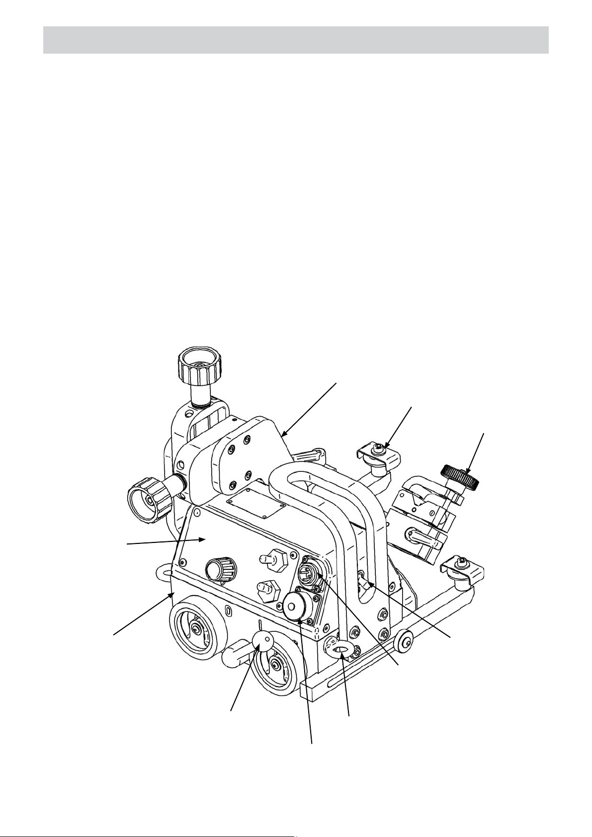
The GECKO Welding Carriage contains a drive system with controller, cross slides, two follower
arms, and torch holder. The drive system comprises a gear motor that drives four rubber wheels
of high thermal resistance.
The magnetic unit with powerful permanent magnets fitted at the carriage bottom ensures
proper adhesion to ferromagnetic surfaces. Toggling the magnetic unit lever (Figure 1) to position
“0” reduces the intensity of the magnetic field, what helps moving the welding carriage during
positioning. The cross slides enable precise control of the torch holder position in both horizontal
and vertical axis. Additionally, the machine can ignite an arc through the arc ignition socket when
choosing a travel direction.
Control Panel
Drive System
Cross Slides
Follower Arm
Torch Holder
Power Switch
Magnetic Unit Lever
Arc Ignition Socket
Figure 1. GECKO Operator’s Manual
Saftey Line Lug
Power Supply Socket
4
Page 6
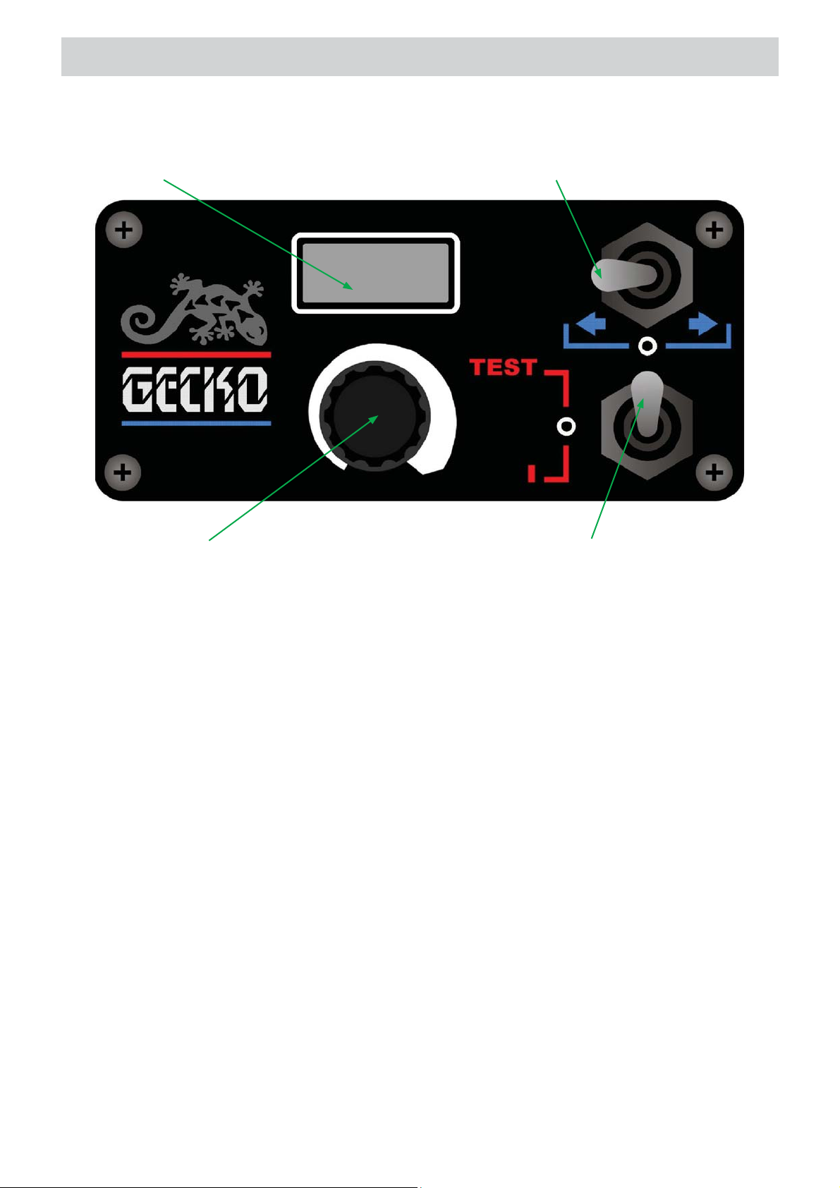
DESIGN
LED Display
Speed Adjusting Knob Arc Ignition Switch (TEST / 0 / 1)
Travel Direction Switch (left / 0 / right)
Figure 2. Control Panel Design
1.4. Equipment included
The GECKO Welding Carriage is supplied with complete standard equipment in a foam filled
cardboard box. The included equipment consists of:
• welding carriage – 1 unit
• foam filled cardboard box – 1 unit
• power cord – 1 unit
• arc ignition cable – 1 unit
• torch holder – 1 unit
• 4 mm Allen key – 1 unit
• Operator’s Manual – 1 unit
5
Page 7

SAFTEY PRECAUTIONS
2. SAFETY PRECAUTIONS
1. Before start, read Operator’s Manual and complete proper occupational safety and
health training.
2. Machine must be used only in applications stated in Operator’s Manual.
3. Machine must be complete and all parts must be genuine.
4. Power supply specifications must conform to those stated on rating plate.
5. Power supply socket must be equipped with grounding pin.
6. Never carry machine by cord or yank it to disconnect plug from socket. It may cause
power cord to break and result in electric shock.
7. Bystanders must not be present in immediate vicinity of machine.
8. Before start, check condition of machine and electrical installation, including power
cord, plug, control panel, and wheels.
9. Keep machine dry. Exposing it to rain, snow, or frost is prohibited.
10. Ensure proper lighting at worksite.
11. Never use machine in vicinity of flammable fluids or gases, or in explosive environments.
12. Make sure that rubber of driving wheels is clean and not damaged.
13. Never disassemble driving wheels cover.
14. Remove objects attracted to chassis by magnetic unit.
15. Transport and position machine using carrying handle, with magnetic unit lever set to
position “0”.
16. Place machine on ferromagnetic material in such a way that wheels always touch
surface and there is no contact between surface and chassis.
17. Do not stay underneath machine placed at heights.
18. Plug power cord into mains only when power switch is set to position “0”.
19. Keep power socket clean. Do not use compressed air for cleaning purposes.
20. Mounting torches other than MIG/MAG type or torches with handle diameter outside
16–22 mm range (0.63–0.87’’) is prohibited.
21. Maximum torch reach must not exceed 70 mm (2.76’’).
22. Keep torch cables from touching surface (they must be suspended to reduce carriage
load). Use only cables which maximum weight is 8 kg (17.7 lbs) for horizontal work
and 6 kg (13.3 lbs) for vertical work.
23. Operating in welding positions: PD (horizontal overhead), PE (overhead), and PG
(vertical down), as well as on curvatures with convex (concave) radius lower than
1000 mm (1250 mm) is prohibited.
24. When operating at heights, use safety line to protect machine from falling down.
25. Always use eye protection (welding helmet, shield, and screen), hearing protection,
gloves, and protective clothing during operation. Do not wear loose clothing.
26. Before every use, inspect machine to ensure it is not damaged. Check whether any
part is cracked or improperly fitted. Make sure to maintain proper conditions that may
affect machine operation.
27. Never try to manually stop motion of machine. For this purpose set travel direction
switch to position “0”.
6
Page 8
SAFTEY PRECAUTIONS
28. Perform all maintenance work only with power cord unplugged from power socket.
29. Perform all repairs only in service center appointed by seller.
30. If machine falls on hard surface, from height, is wet, or has other damage that could
affect technical state of machine, stop operation and immediately send machine to
service center for inspection.
31. Never leave machine unattended during operation.
32. Remove from worksite and store in safe and dry location when not in use.
WARNING! Safety rules must be closely observed.
7
Page 9
STARTUP AND OPERATION
3. STARTUP AND OPERATION
WARNING! Read safety precautions before starting.
3.1. Preparation
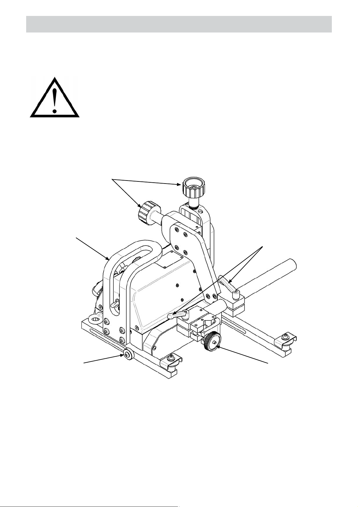
Use carrying handle (Figure 3) for transportation and positioning at the worksite. Set all levers
to position “0”: power switch, magnetic unit lever, travel direction switch, and arc ignition switch.
Precise Torch Adjusting Knobs
Carrying Handle
Bolt Securing Follower Arms
Levers Securing Torch
Position and Angle
Knob Securing Torch Into Holder
Figure 3. Control units
Plug the cord into machine power supply socket, put a torch into torch holder, and secure with
knob. If the machine is to be used to control the welding device, plug supplied arc ignition cable
into the arc ignition socket. The cable works as a welding gun switch and comprises two wire
pairs of a different color. Connecting each pair enables to control arc ignition of one welder.
8
Page 10
STARTUP AND OPERATION
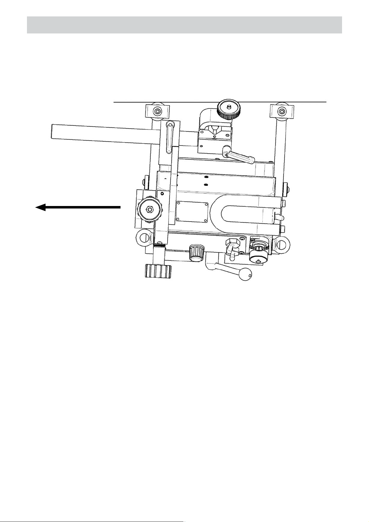
To continuously track the travel geometry, set the first follower arm 10 mm (0.4’’) closer to the
machine than the second one (Figure 4). For this purpose, use 4 mm Allen key to unscrew the
bolt that secures the follower arms and screw the bolt after the setting has been made.
Travel Direction
Figure 4. Proper follower arms position
Toggle the magnetic unit lever from left (“0”) to right position (“1”), what changes the machine
adhesion to work surface from the minimum to maximum. Loosen the levers (Figure 3) and adjust
the position and angle of the torch. Set the torch position precisely using the two knobs located at
the cross slides. If the work is to be done along the vertical axis, perform welding upward (position
PF according to the EN ISO 6947). When operating at heights, attach a safety line to the lug. The
safety line is not included in the standard equipment.
3.2. Operation
Plug the power cord into the mains and turn on the power by toggling power switch to position
“I”, which will indicated by the illuminating all the segments of the display (“888”). After a while,
the indication changes to “EUr” if the unit of speed is set to centimeters per minute, or to “USA”
– for inches per minute. Then, you will see the carriage speed, which you adjust by rotating the
knob located on the panel. If the machine is to be used to control the torch, toggle the arc ignition
switch to position “I”. To check whether the arc ignition cable is connected correctly, toggle the
switch to position “TEST”.
9
Page 11
STARTUP AND OPERATION
WARNING: If the arc ignition switch is set to position “I”, the torch starts welding
immediately after setting a travel direction.
Choose a motion direction using the travel direction switch. The real speed of the welding carriage
shows up on the display. To stop the motion, set travel direction switch to position “0”.
3.3. Changing unit of speed
To change the unit of speed from centimeters per minute to inches per minute, or vice versa,
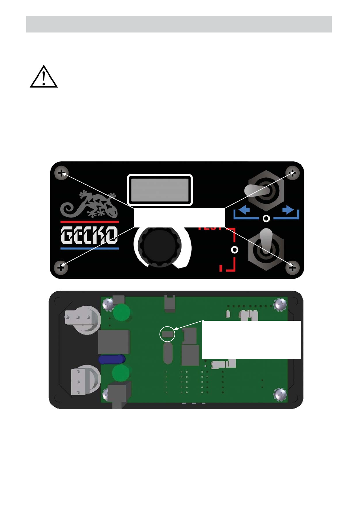
unplug the power cord from the mains and follow steps shown in the Figure 5.
Use a 2.5 mm Allen key to loosen
bolts that secure the control panel.
The joint is used to change the unit
of speed. If the jumper is in place,
the speed is displayed in centimeters
per minute. Removing the jumper
changes the unit to inches per minute.
Figure 5. Method of changing the unit of speed
Once you change the unit and power the machine again, the actual unit shows up. With the
jumper removed, the display shows “USA” message and the speed is indicated in inches per
minute. With jumper in place, the display shows “EUr” and the speed is given in centimeters
per minute. The 2.5 mm Allen key used to unscrew the control panel is not included in standard
equipment.
10
Page 12
STARTUP AND OPERATION
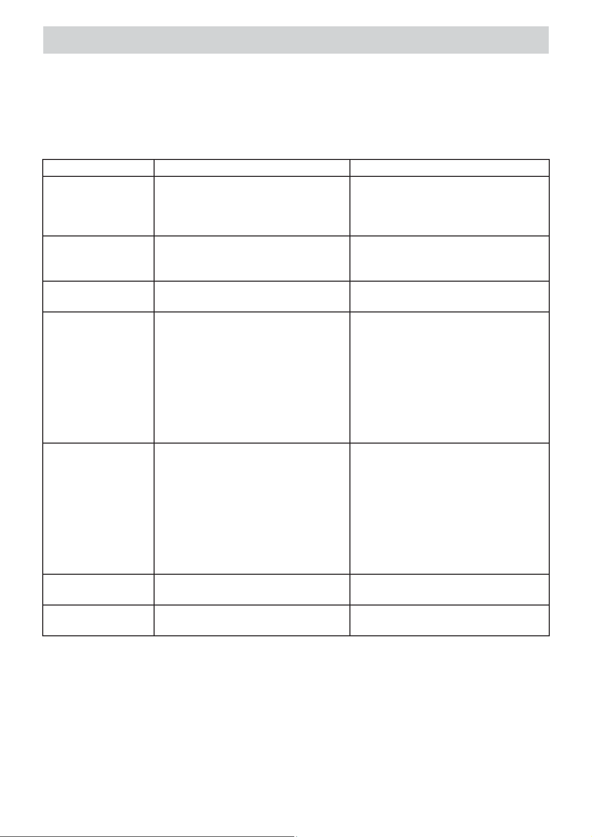
3.4. Meaning of display messages
Message Description Solution
8.8.8. Display test
If some segments are not
illuminated, it indicates a problem
with the display.
EUr Indicates that the speed is
displayed in centimeters per
minute.
USA Indicates that the speed is
displayed in inches per minute.
Er.S Travel direction switch error
1. Travel direction switch is active
(left or right direction chosen) when
powering up.
2. If displayed during welding,
it indicates a malfunction of
travel direction switch or travel
direction identification circuit of the
controller.
crL Motor overload
Motor safe current level
exceeded. Welding carriage stops
immediately.
110 Maximum speed in centimeters per
minute for horizontal work.
43.4 Maximum speed in inches per
minute for horizontal work.
Contact service center to
investigate the problem.
-
-
1. Set travel direction switch to
position “0”.
2. Contact service center. Possible
switch or controller fault.
Use welding cables that do not
exceed maximum weight stated in
technical data.
Adjust arrangement of the cables
that block carriage motion.
Remove any other elements that
block the carriage or its wheels.
If this message still appears,
contact service center.
-
-
11
Page 13
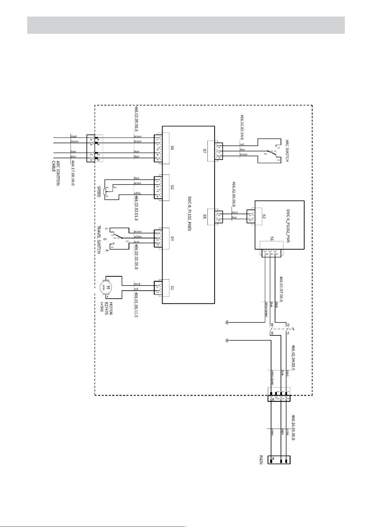
4. WIRING DIAGRAM
WIRING DIAGRAM
12
Page 14
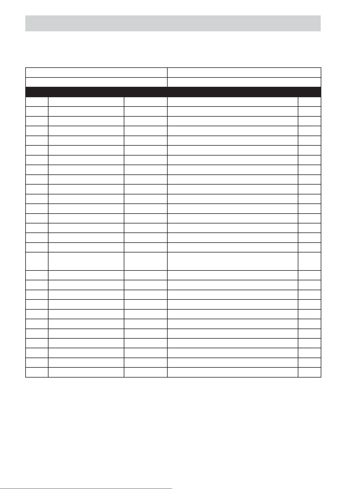
PARTS LIST - GENERAL ASSEMBLY
WOZ-0466-10-20-00-0 GECKO /230V
WOZ-0466-10-10-00-0 GECKO /115V
ITEM PART NUMBER VERSION DESCRIPTION Q-TY
1 WOZ-0466-11-00-00-0 2060 DRIVE SYSTEM ASSY 1
ZSP-0466-03-00-00-0 2062 CROSS SLIDES ASSY 1
2
3 UCW-0466-04-00-00-0 2064 TORCH HOLDING ASSY 1
4 PLY-0466-05-00-00-0 2066 TORCH PLATE COMPLATE 1
5 WSP-0466-07-00-00-0 2068 SLIDE BRACKET 1
6 RKJ-0466-08-00-00-0 2070 HANDLE 1
7 SRB-000083 HEX SOCKET BOLT M5x16 4
8 SRB-000114 HEX. SOCKET BOLT M6x20 4
9 SRB-000075 HEX SOCKET BOLT M5x10 8
10 PDK-000018 WASHER 5.3 8
11 TBL-0466-15-01-03-0 NAME PLATE 1
12 NIT-000010 ROUND HEAD RIVET 2x6 4
13 GLK-0466-12-00-00-0 2141 HANDLE KNOB 1
14 DZW-0419-01-04-13-0 LEVER 1
15 KUL-0466-13-00-00-0 2143 BALL LEVER 1
16 PNL-0466-02-02-00-1 2636 CONTROL PANEL ASSEMBLY 1
17 WKR-000092 SOCKET BUTTON HEAD CAP SCREW
M4x10
18 WKR-000048 SOCKET SET SCREW M5 x 6 1
19 NKL-0466-15-00-02-0 LOGO LABEL “STEELMAX” 1
20 PDK-000021 ROUND WASHER 6,4 4
22 UCW-0476-06-00-00-0 2072 LOW TORCH HOLDING ASSY 1
23* ZST-0466-25-00-00-0 2492 EQUIPMENT SET 1
23.1* PWD-0466-18-00-00-0 POWER CORD 230V 1
23* ZST-0466-25-00-00-0 2121 EQUIPMENT SET 1
23.1* PWD-0466-16-00-00-0 POWER CORD 115V 1
23.2* KBL-0466-17-00-00-0 CONTROL CABEL START-STOP 1
23.3* KLC-000007 HEX. WRENCH S=4 1
23.4* INS-0239-55-00-00-1 OPERATORS MANUAL 1
* - not shown on drawing
4
13
Page 15
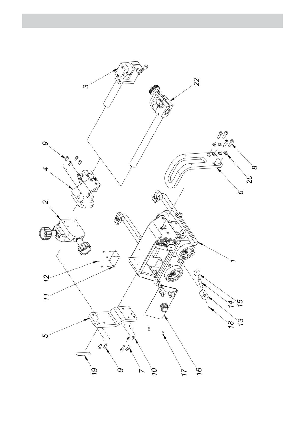
PARTS LIST - GENERAL ASSEMBLY
14
Page 16
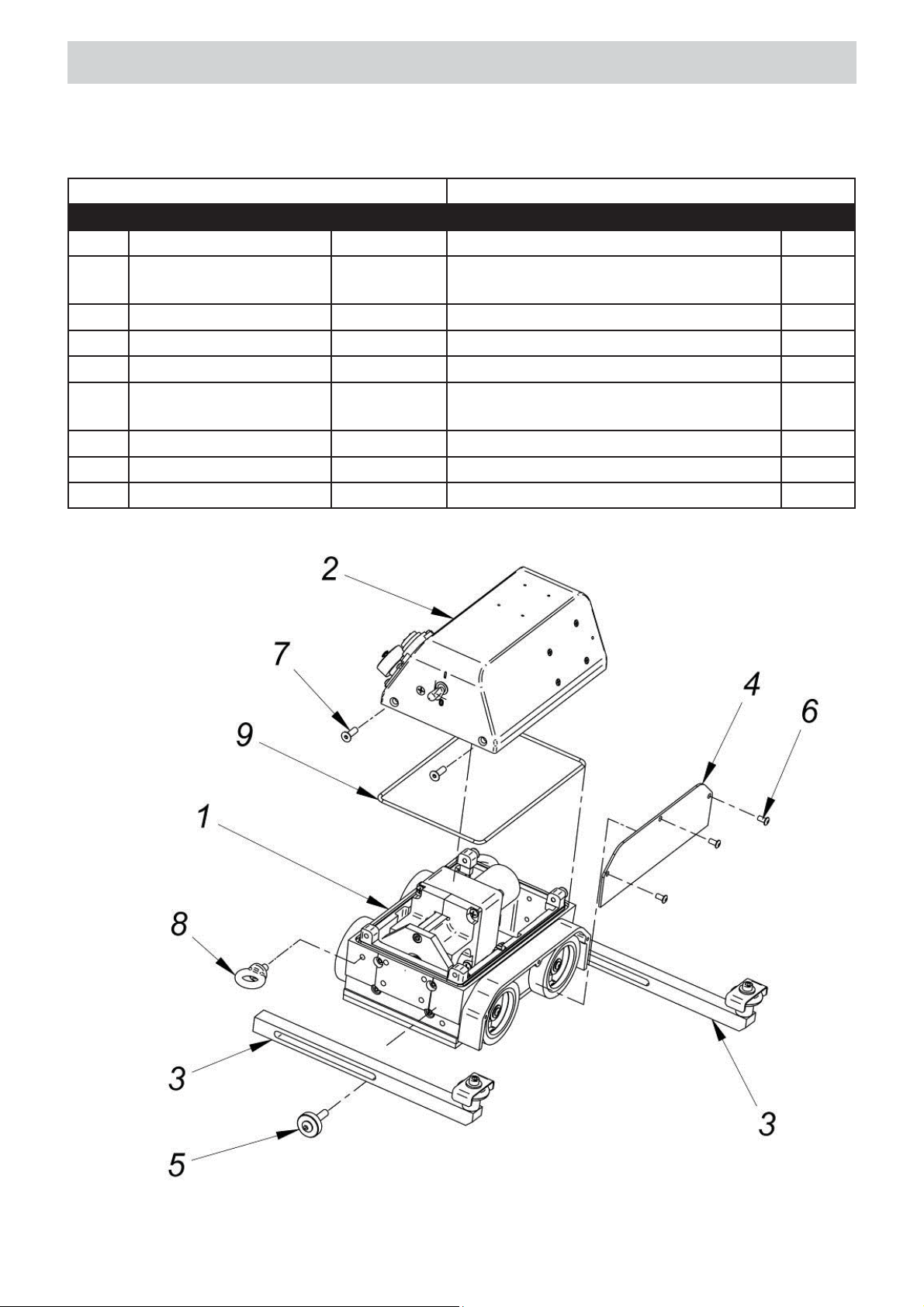
PARTS LIST - DRIVE SYSTEM ASSEMBLY
WOZ-0466-11-00-00-0 DRIVE SYSTEM ASSY
ITEM PART NUMBER VERSION DESCRIPTION Q-TY
1.1 ZSP-0466-01-00-00-0 2074 DRIVE SYSTEM 1
1.2
1.3 PRW-0466-06-00-00-0 2076 FOLLOWER ASSEMBLY 2
1.4 OSL-0466-09-00-00-0 2077 WHEEL GUARD 1
1.5 SRB-0466-10-00-00-0 FOLLOWER SCREW 2
1.6 WKR-000091 SOCKET BUTTON HEAD CAP
1.7 WKR-000136 SCR, M5 x 16 FHSCS 4
1.8 SRB-000278 EYE BOLT M6 2
1.9 PRS-000266 SEAL O-RING 173x3 1
OBD-0466-02-00-00-0 2490 CONTROLLER HOUSING
COMPLETE
SCREW M4x8
1
3
15
Page 17
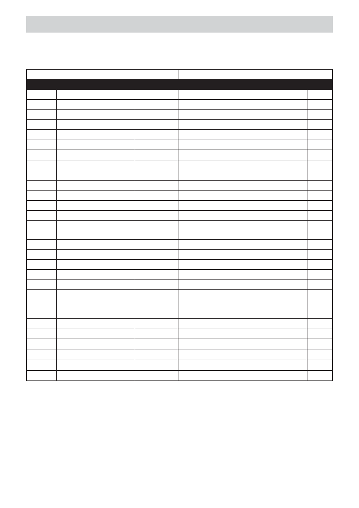
PARTS LIST - DRIVE SYSTEM
ZSP-0466-01-00-00-0 DRIVE SYSTEM
ITEM PART NUMBER VERSION DESCRIPTION Q-TY
1.1.1 KRP-0466-01-01-00-1 2078 FRAME 1
1.1.2
1.1.3 WLK-0466-01-03-00-0 BACK DRIVE SHAFT ASSY 1
1.1.4 BLO-0466-01-04-00-0 2079 MAGNET BLOCK ASSEMBLY 1
1.1.5 KOL-0466-01-05-00-0 INDIRECT GEAR WHEEL ASSY z30 1
1.1.6 MTR-0466-01-06-00-0 MOTOR ASSEMBLY 1
1.1.6.1 SLN-0466-01-06-10-0 MOTOR 1
1.1.7 KOL-0466-01-07-00-0 2080 DRIVE WHEEL 4
1.1.8 KOL-0466-01-08-00-0 BEVEL GEAR z30 1
1.1.9 ZSP-0466-01-09-00-0 LEVER ASSEMBLY 1
1.1.10 PDK-0466-01-10-00-0 SPACER WASHER 4
1.1.11 KOL-0456-01-05-00-0 INTERMEDIATE GEAR ASSY 2
1.1.12 PDK-000164 ROUND WASHER 12x18x1 2
1.1.13 TLJ-000088 SELF-LUBRICATING BRUSHUNG
1.1.14 LOZ-000038 BEARING 6001 ZZ 4
1.1.15 WPS-000027 WOODRUFF KEY 3x5x13 1
1.1.16 PRS-000018 INTERNAL RETAINING RING 28W 4
1.1.17 PRS-000005 EXTERNAL RETAINING RING 15z 2
1.1.18 SRB-000082 HEX. SOCKET BOLT M5x14 3
1.1.19 SRB-000061 HEX SOCKET BOLT-M4X10 1
1.1.20 WKR-000092 SOCKET BUTTON HEAD CAP
1.1.21 WKR-000136 SCR, M5 x 16 FHSCS 8
1.1.22 WKR-000434 FHSCS M4x20 1
1.1.23 PDK-000108 ROUND WASHER 4,3 7
1.1.25 PDK-000017 ROUND WASHER 5,3 3
1.1.26 PDK-000060 SPRING WASHER 4,3 2
WLK-0466-01-02-00-0 FRONT DRIVE SHAFT ASSY 1
1
FLANGE
4
SCREW M4x10
1.1.27 NKR-000031 NUT M4 SHORT 2
16
Page 18
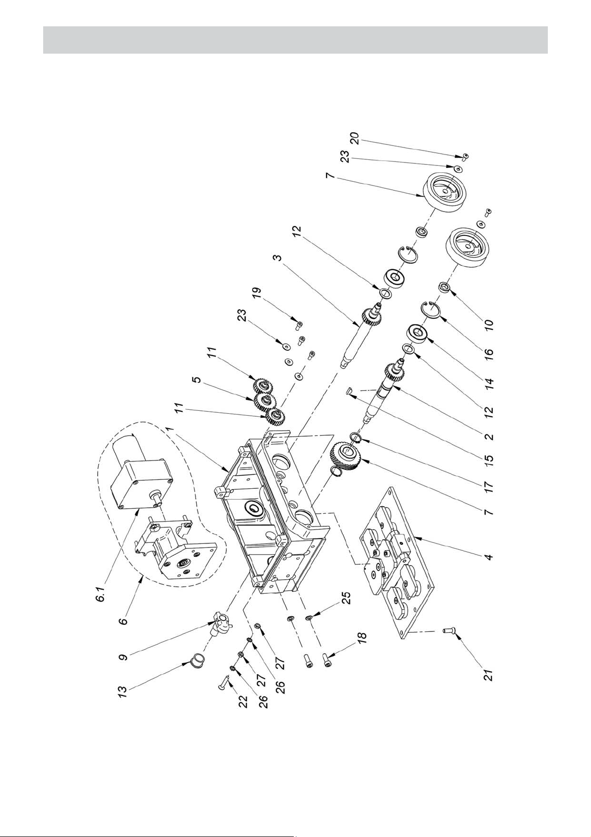
PARTS LIST - DRIVE SYSTEM
17
Page 19
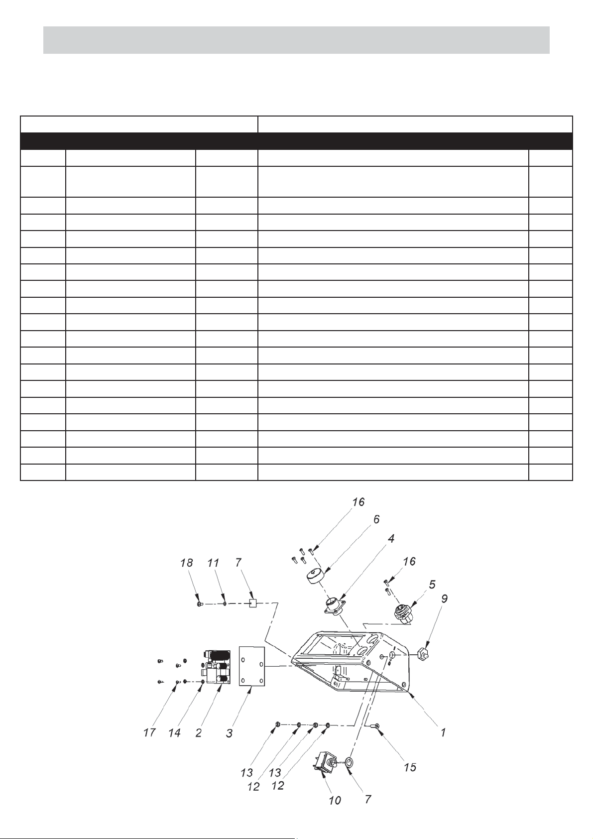
PARTS LIST - CONTROLLER HOUSING COMPLETE
OBD-0466-02-00-00-0 CONTROLLER HOUSING COMPLATE
ITEM PART NUMBER VERSION DESCRIPTION Q-TY
1.2.1 PKR-0466-02-01-00-0 2082 CONTROLLER HOUSING COVER 1
1.2.2
1.2.3 PLY-0466-02-08-00-0 INSULATING PLATE 1
1.2.4 WZK-0466-02-05-00-0 IGNITION SOCKET WIRE SET 1
1.2.5 WZK-0466-02-04-00-0 POWER SOCKET WIRE SET 1
1.2.6 NKR-000120 SAFETY NUT 1
1.2.7 PDK-000098 SILICONES WASHER 20x15 1
1.2.8 PDK-000165 LOCKING WASHER 12/19 1
1.2.9 OSL-000036 LEVER KEY COVER 1
1.2.10 PNK-000026 LEVER KEY, 641 H/3 1
1.2.12 PDK-000060 SPRING WASHER 4,3 2
1.2.13 NKR-000013 HEX NUT M4 2
1.2.14 PDK-000058 WASHER, LOCK, INTERNAL STAR M3 4
1.2.15 WKR-000152 SCREW M4 x 16 1
1.2.16 WKR-000427 CROSS RECESSED SCREW M3x8 6
1.2.17 WKR-000428 CROSS RECESSED SCREW M3x8 4
1.2.18 WKR-000414 LOTTED PAN HEAD MACHINE SCREWS M3x8 1
1.2.19 WZK-0466-02-06-00-0 PANEL WIRE SET 1
1.2.20 WZK-0466-02-07-00-0 POWER WIRE SET 1
* - not shown on drawing
MDL-0466-02-03-00-0 POWER SUPPLY ELECTRONIC CONTROLLER
ASSY
1
18
Page 20
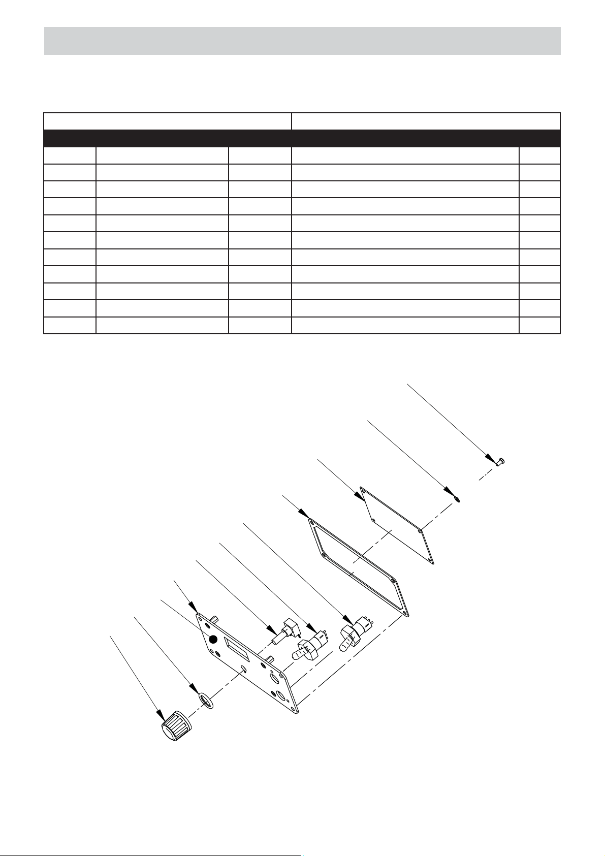
PARTS LIST - PANEL ASSEMBLY
PNL-0466-02-02-00-1 PANEL ASSEMBLY
ITEM PART NUMBER VERSION DESCRIPTION Q-TY
16.1 MSK-0466-02-02-10-1 2638 PANEL PLATE ASSY 1
16.1.1
16.2 STR-0466-02-02-02-0 ELECTRONIC CONTROLLER 1
16.3 PKT-000028 POTENCIOMETER KNOB 1
16.4 WZK-0466-02-02-01-0 POTENCIOMETER WIRE SET 1
16.5 WZK-0466-02-02-04-0 IGNITION WIRE SET 1
16.6 WKR-000181 CROSS RECESSED SCREW M3x6 4
16.7 PDK-000058 WASHER, LOCK, INTERNAL STAR M3 4
16.8 WZK-0466-02-02-05-0 DIRECTION OF MOTION WIRE SET 1
16.9 PRS-000095 O-RING 12x2 1
16.10 USZ-0466-02-02-03-0 PANEL PLATE SEAL 1
NKL-0466-15-01-01-1 PANEL PLATE LABEL 1
6
7
2
10
8
5
4
1
1.1
9
3
19
Page 21
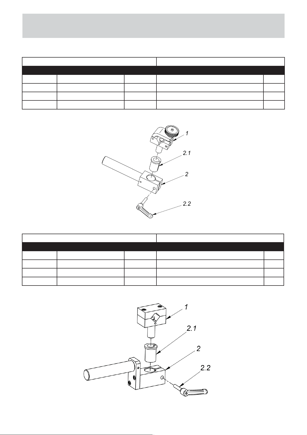
PARTS LIST - TORCH HOLDING ASSEMBLY
& LOW TORCH HOLDING ASSEMBLY
UCW-0476-20-00-00-0 TORCH HOLDING ASSY
ITEM PART NUMBER VERSION DESCRIPTION Q-TY
10.1 ZRZ-0466-04-01-00-0 2093 TORCH CLAMP ASSY, 1
10.2
10.2.1 TLJ-0419-04-02-03-0 INSULATION SLEEVE, 1
10.2.2 RKJ-000036 HANDLEVER GN 300-45-M6-32-SW, 1
WLK-0466-04-10-00-0 2708 LONG TORCH BRACKET ASSY
UCW-0476-06-00-00-0 LOW TORCH HOLDING ASSY
ITEM PART NUMBER VERSION DESCRIPTION Q-TY
22.3.1 ZCS-0476-06-01-00-0 2108 CLAMPING BLOCKS 1
22.3.2
22.3.2.1 TLJ-0419-04-02-03-0 INSULATION SLEEVE 1
22.3.2.2 RKJ-000036 HANDLEVER GN 300-45-M6-32-SW 1
TRM-0476-06-10-00-0 2811 TORCH BRACKET ASSY
20
 Loading...