

Page 1
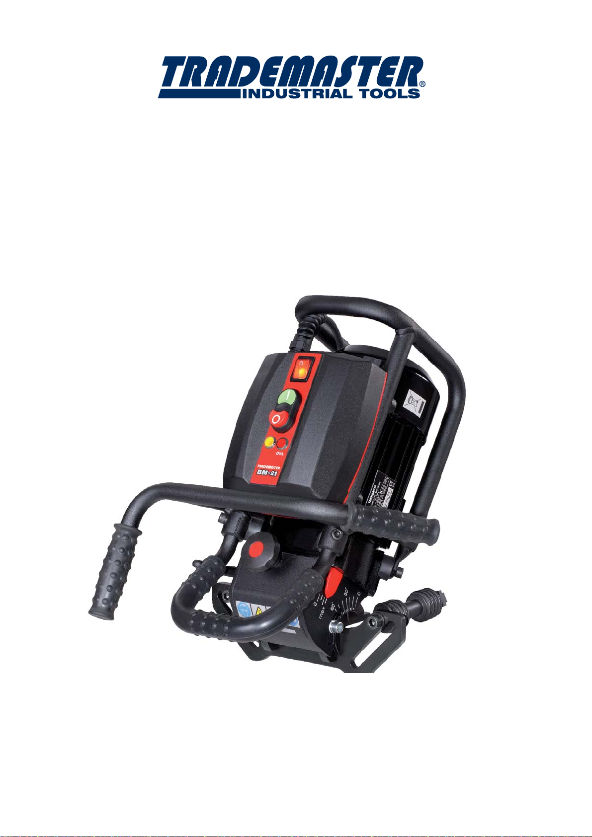
OPERATOR’S MANUAL
BM-21
BEVELLING MACHINE
Page 2

IMPORTED & DISTRIBUTED BY
18 BUSINESS ST
YATALA QLD 4207 AUSTRALIA
07 3287 1114
T
07 3287 1115
F
E
www.industrialtool.com.au
W
INDUSTRIAL TOOL & MACHINERY SALES
WARRANTY TERMS
In addition to any warranties or conditions implied by applicable Statute or Regulations,
Industrial Tool & Machinery Sales warrants all of it’s products against defective workmanship
and faulty materials for a period of twelve (12) months from the date of purchase, unless otherwise stated. At our option we will repair or replace, free of charge, any item on the condition that:
- The complete machine or tool is returned, freight prepaid to ITM or one of it’s authorised
service agents as directed by ITM, and is found to have a material or constructional defect.
- The machine or tool has not been subject to misuse, neglect or damage by accident.
- The fault is not a result of normal “wear and tear”.
- Written permission has been received from ITM prior to commencement of repair.
- Repairs, tampering or modification carried out by unauthorised personnel will void all warranty.
- Consumable items such as cutting tools, pilot pins, saw blades, grinding wheels etc. are
NOT covered by warranty.
Our goods come with guarantees which cannot be excluded under the Australian Consumer
Law. You are entitled to replacement or refund for a major failure and to compensation
for other reasonably foreseeable loss or damage. You are also entitled to have the goods
repaired or replaced if the goods fail to be of acceptable quality and the failure does not
amount to a major failure.
Read Operator’s Manual
before you start to work with the machine
Operator’s Manual – BM-21 Bevelling Machine
2
Page 3

CONTENTS
1. GENERAL INFORMATION.................................................................4
1.1. Application....................................................................................4
1.2. Technical data..............................................................................4
1.3. Equipment included ....................................................................5
2. SAFETY
3. STARTUP AND OPERATION.............................................................8
3.1. Preparing to operation..................................................................8
3.2. Adjusting bevel width and angle...................................................9
3.3. Bevelling metal plates.................................................................10
3.4.Bevelling pipes............................................................................10
3.5.Bevelling larger pipes (only for optional equipment)...................13
3.6.Replacing cutting inserts.............................................................14
3.7.Replacing milling head................................................................15
4. WIRING DIAGRAM...........................................................................16
PRECAUTIONS....................................................................6
Operator’s Manual – BM-21 Bevelling Machine
3
Page 4
1. GENERAL INFORMATION
GENERAL INFORMATION
1.
1.1. Application
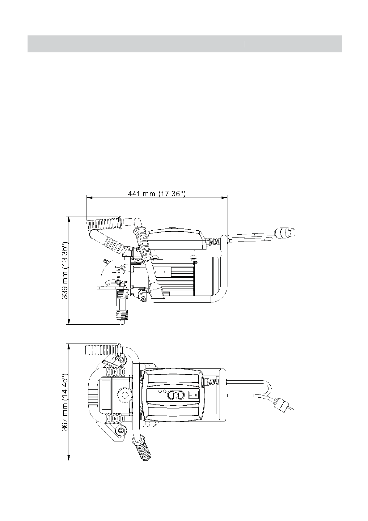
The BM-21 Bevelling Machine is designed for milling edges of plates and pipes
made of carbon steel. The machine enables the bevelling of sheet steel edges and
pipe edges with diameters from 150 mm (6’’) to 300 mm (12’’) in 0–60° angular range
with maximum bevel width of 21 mm (13/16’’). When equipped with the optional
guide available on request, it can also work on pipes with diameters above 300 mm
(12’’). The machine contains dampers that enable more comfortable operation, reducing unwanted vibrations.
1.2. Technical data
Operator’s Manual – BM-21 Bevelling Machine
4
Page 5
Voltage ~ 220–240 V, 50–60 Hz
Electric motor
Single-phase induction motor with run
capacitor; 1100 W
Power 1600–1800 W
Rotational speed 2780–3340 rpm
Protection level IP 20
Milling speed 550–650 m/min (1800–2200 ft/min)
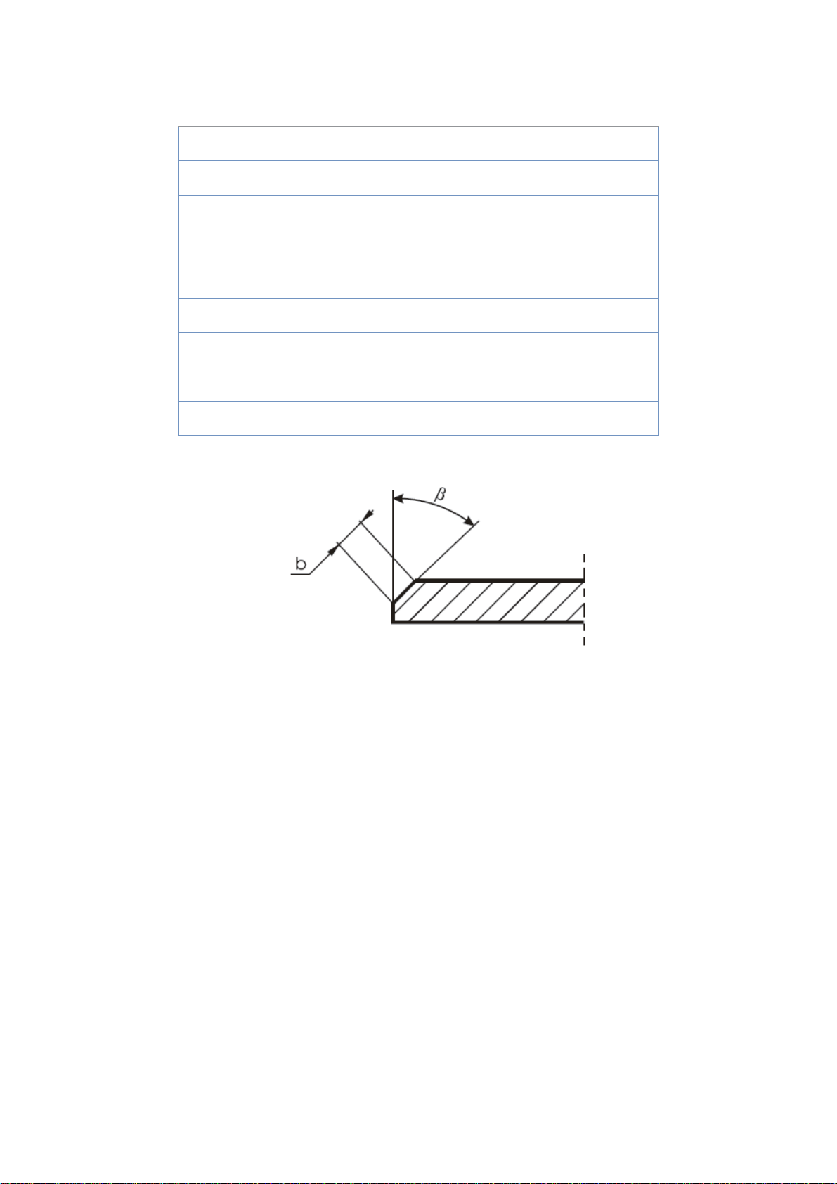
Maximum bevel width b 21 mm (13/16’’, Figure 1)
Bevel angle range 0° ß 60° (Figure 1)
Weight Approx. 23 kg (51 lbs)
Milling tool is equipped with 10 removable multi-edge cutting inserts made of carbide.
Figure 1. Bevel dimensions
1.3. Equipment included
BM-21 Bevelling Machine is supplied in metal box with complete standard equipment.
The included equipment consists of:
• bevelling machine with a set of cutting inserts – 1 unit
• metal box – 1 unit
• size 8 Allen key – 1 unit
• size 6 Allen key – 1 unit
• size 4 Allen key – 1 unit
• size 12 flat key – 1 unit
• torx T15 screwdriver – 1 unit
• Operator’s Manual – 1 unit
Operator’s Manual – BM-21 Bevelling Machine
5
Page 6

2. SAFETY PRECAUTIONS
Using the machine is not allowed if:
1. Operator has not read Operator’s Manual or has not completed proper occupational safety and
health training.
2. Machine is to be used in applications not stated in Operator’s Manual.
3. Machine is not complete or parts used for repair are not genuine.
4. Power supply specifications do not conform to those stated on rating plate.
5. Operator has not checked condition of machine, including power cord, control panel components
and milling tools.
6. Power supply socket is not equipped with earthing pin.
7. Bystanders are present in immediate vicinity of machine.
Detailed safety rules:
1) Before you start to work with machine, check condition of electrical installation, including power
cord and plug.
2) Connect machine only to power sockets equipped with a safety circuit (earthing) protected with
16A fuse for 230 V supply. When used on building sites, supply power to machine through
a separation transformer with a class 2 power supply.
3) Never carry machine by cord or pull it to disconnect plug from socket. It may cause power cord
to break and result in electric shock.
4) Keep machine dry. Exposing it to rain or snow is prohibited.
5) Ensure proper lighting on your worksite.
6) Never use machine in vicinity of combustible fluids or gases or in explosive environments.
7) Always use safety goggles, hearing protection, gloves and protective clothing during operation.
Do not wear loose clothing!
8) Never use blunt or damaged tools.
9) Never remove hot and sharp metal chips with bare hands.
10) Securely fasten cutting inserts in milling head using fastening screws.
WARNING! Do not hold rotating parts
of the machine or metal chips formed during milling!
Operator’s Manual – BM-21 Bevelling Machine
6
Page 7

11) If cutting edge of insert is worn out, rotate insert in socket by 90° or, if all edges are worn out,
replace with new insert specified in Operator’s Manual.
12) Before every use, inspect machine to ensure it is not damaged. Check whether any part is
cracked and whether all parts are properly fitted. Make sure to maintain proper conditions that
may affect machine operation.
13) Maintain machine and tools with care. Cover steel parts with thin grease layer to protect them
against rust when not in use for a long period.
14) After every use, remove metal chips from machine, particularly from milling head, ensuring that
power cord is unplugged from power socket.
15) Use only parts recommended by manufacturer and specified in Operator’s Manual.
16) Perform all maintenance work and repairs only with power cord disconnected from power socket.
17) Replace damaged parts of machine only with genuine parts.
18) Perform all mechanical and electrical repairs only in service centre appointed by seller.
19) If machine falls on a hard surface, from a height, is wet or has other damage that could affect
technical state of machine, stop operation and immediately send machine to service centre for
inspection.
WARNING! Do not hold rotating parts.
Safety rules must be closely observed.
Operator’s Manual – BM-21 Bevelling Machine
7
Page 8
START UP AND OPERATION
START UP AND OPERATION
WARNING! Read safety precautions
before you start to work with the machine.
3.1. Preparing for operation
Before performing any work, set required bevel width and angle (see “Adjusting bevel width and angle”
pg 9).
After setting proper values, plug the machine into an earthed power socket. Place machine
vertically on the right edge of workpiece in a way that milling head does not touch working edge. Then,
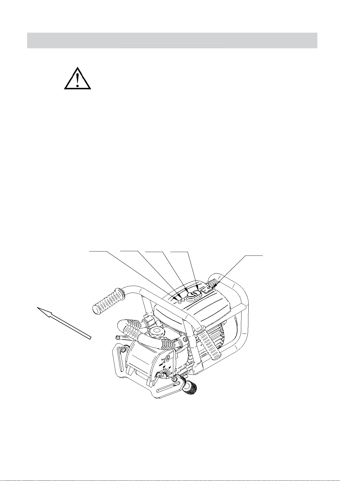
turn on the power by pressing main switch located on the motor housing (Figure 2, Item 1) to “I” position,
what will be indicated by amber light. The green button marked “I” (Figure 2, Item 2) is used to start the
machine, pressing red button marked “0” (Figure 2, Item 3) stops the machine. To turn off the power,
press main switch back to “0” position. The yellow lamp (Figure 2, Item 4) indicates operation of the tool.
Pressing vertical guide to the working edge, slowly slide machine until the tool starts to cut steel.
Bevelling is performed according to counter-rotation. The proper feed direction is shown in Figure 2;
direction of milling head rotation is indicated on the motor disc under milling head cover.
5
4
3
2
1
Figure 2. Control panel design and proper machine feed direction
Operator’s Manual – BM-21 Bevelling Machine
8
Page 9
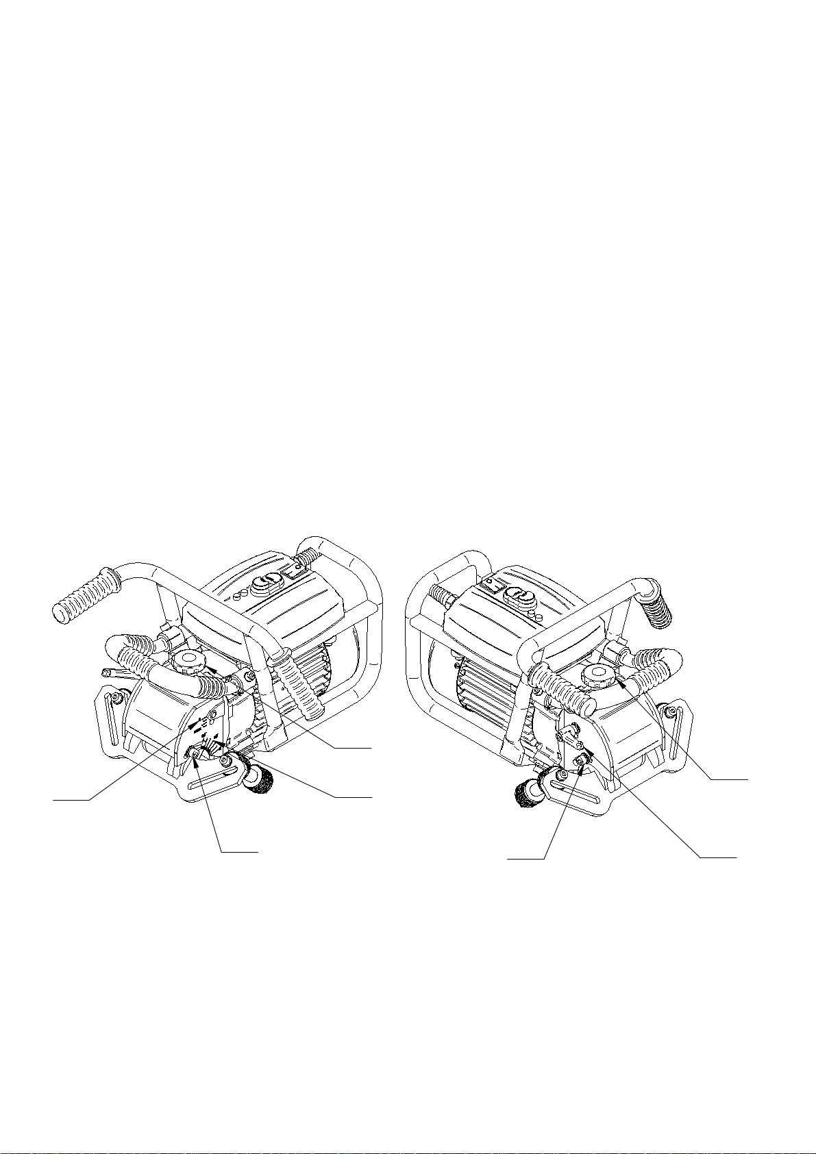
3.2. Adjusting bevel width and angle
The machine enables easy and quick adjustment of bevel parameters. Before performing adjustments, ensure that the power cord is unplugged from power socket. Adjustment of the bevel angle starts
with milling head penetration set to zero (indication “0” on the milling head cover side wall).
To change bevel angle, use size 6 Allen key and loosen two M8 bolts (Figure 3, Item 1) that lock machine guide. Then, turn the guide, setting required angle on the scale located on milling head cover side
wall (Figure 3, Item 3) and secure the bolts afterwards.
To adjust bevel width, change penetration of the milling head: loosen M8 lever (Figure 3, Item 2) and
turn adjusting knob (Figure 3, Item 5) to obtain required width.
The pitch that indicates milling head penetration (Figure 3, Item 4) is only an estimate, because
bevel width varies with angle. For example, for the angle of 10° the maximum width “b” (Figure 1) is
approximately equal 18 mm (11/16’’), while the scale indicates 9 mm (6/16’’). Increasing penetration at
this angle will distort the bevel. You can obtain maximum bevel width (b 21 mm, 13/16’’) for the angle
of 45°. Experimentally determine the required bevel width for individual angles, by gradually increasing
milling head penetration into the working piece.
5
5
4
1
3
1
2
Figure 3. Adjusting bevel width and angle
Operator’s Manual – BM-21 Bevelling Machine
9
Page 10

3.3. Bevelling metal plates
Slide the bevelling machine to the left. Note that the feed rate depends on the profile and
composition of the working material. You can bevel the majority of weldable steels in just one pass.
It is recommended to perform bevels wider than 12 mm (1/2’’) in at least two or three passes.
To obtain maximum bevel width (21 mm, 13/16’’) in two passes, first pass should be 14 mm wide
(9/16’’), whereas for three passes the first one should be 12 mm wide (1/2’’) and the second one
should be 16 mm wide (5/8’’).
If the feed is too fast, a red signal lamp illuminates, indicating motor overload (Figure 2, Item 5).
Further load increasing triggers safety circuit and shuts down the motor. In this case, move the tool away
from bevelled edge, press main switch to “0” position and after red signal lamp turns off press main
switch back to “I” position. Operation with the maximum permitted load (with flashing red signal lamp) is
technically possible, but motor temperature should not exceed 85°C (185°F). The motor can work under
high temperatures, but long overheating may permanently damage the windings. Therefore, after every
hour of working under full load, stop the motor to cool it down for 10–15 minutes. Do not cool the motor
down by leaving it in the idle state, because it will become heated even faster than when working with
load.
3.4. Bevelling pipes
The guide with rollers supplied as a part of standard equipment enables to bevel pipes with
diameters 150–300 mm (6–12’’).
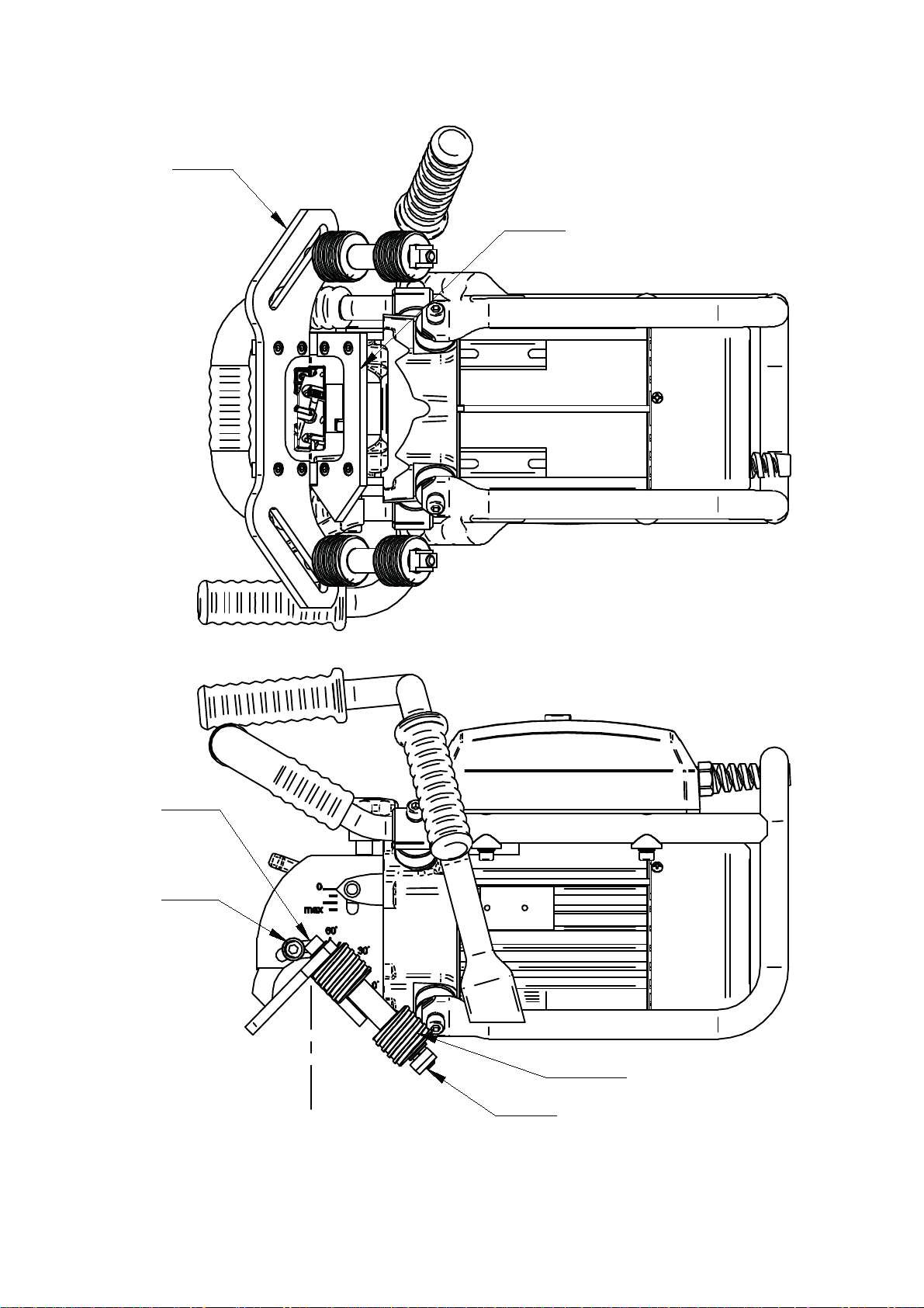
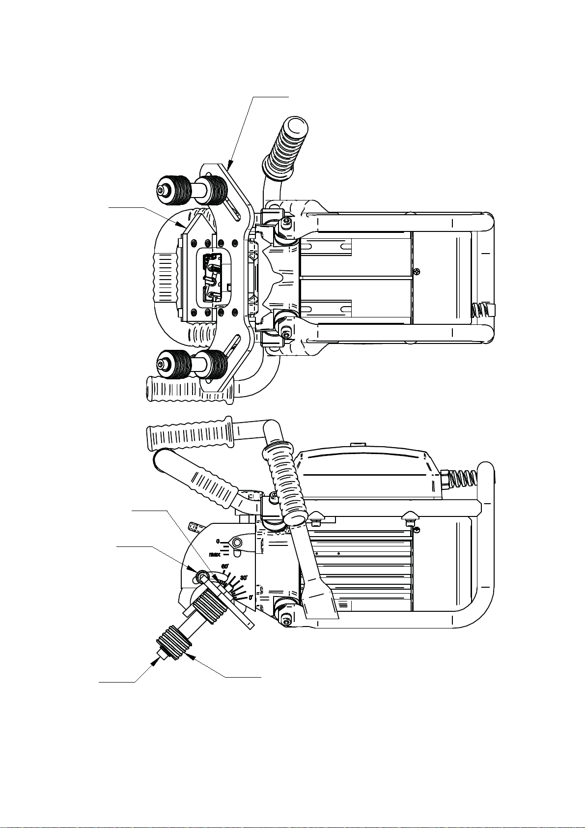
To prepare the machine for work on pipes, unscrew two M8 bolts (Figure 4a, Item 2) using size 6
Allen key. Then, take out the guide set (Figure 4a, Item 1, 5), rotate it by 180º around the axis indicated
in Figure 4a, mount as shown in Figure 4b and secure again with M8 bolts. Using size 8 Allen key and
size 12 flat key, unscrew bolts (Figure 4a, Item 4) that secure the rollers. Then, move rollers (Figure 4a,
4b, Item 3) from opening (Figure 4a) to slot (Figure 4b), placing T-nut (Figure 4a, 4b, Item 6) into the
slot.
Using adjusting knob (Figure 3, Item 5), set “0” position on the pitch (Figure 3, Item 4).
Move rollers away from each other and place the machine as shown in Figure 5, with horizontal guide
(Figure 4b, Item 5) touching the pipe. Then, move rollers (Figure 4a, 4b, Item 3) symmetrically to touch
the pipe and secure with bolts (Figure 4b, Item 4) in this position. Adjust required bevel width and angle
(see “Adjusting bevel width and angle”) and start to work with bevelling machine.
Operator’s Manual – BM-21 Bevelling Machine
10
Page 11
1
5
4
2
3
6
Figure 4a. Machine prepared for work on metal plates
Operator’s Manual – BM-21 Bevelling Machine
11
Page 12
1
5
4
2
6
3
Figure 4b. Machine prepared for work on pipes
Operator’s Manual – BM-21 Bevelling Machine
12
Page 13
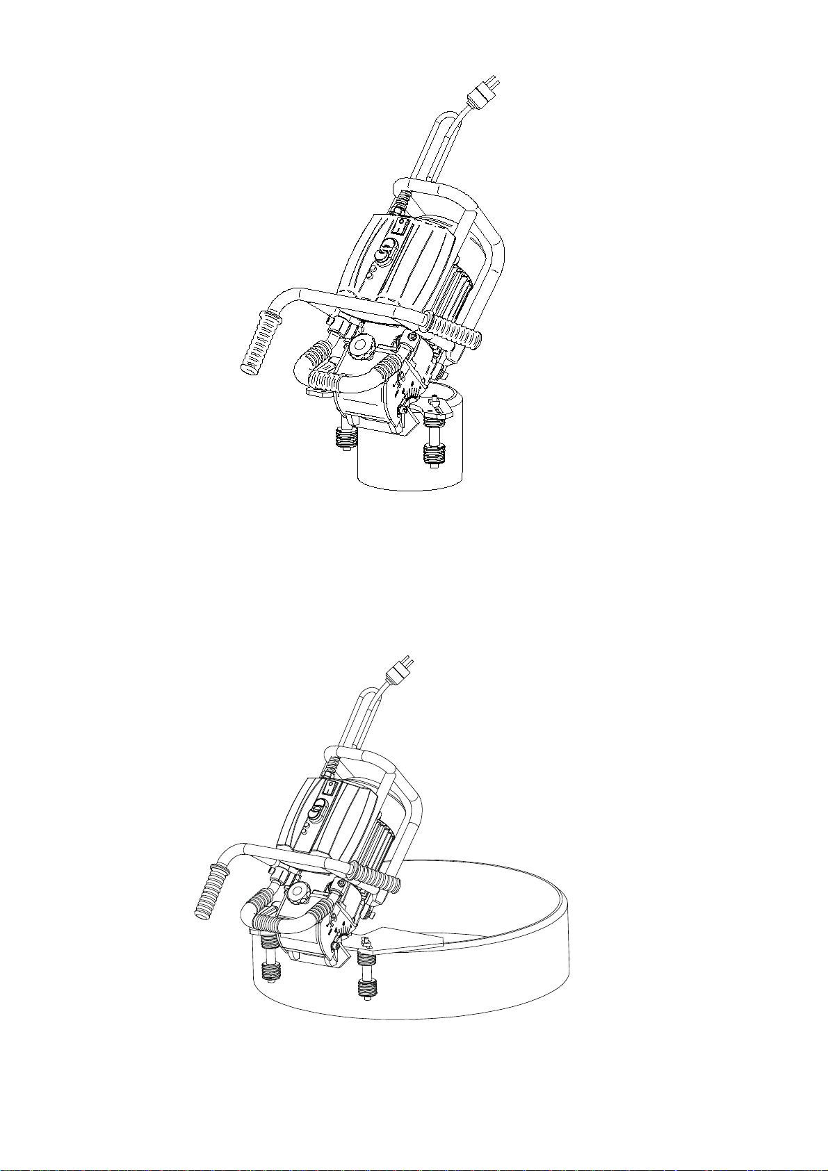
Figure 5. Machine prepared for work on smaller pipes ( 150–300 mm, 6–12’’)
3.5. Bevelling larger pipes (only for optional equipment)
You can optionally order the guide for bevelling larger pipes with diameters 260–600 mm (
10–24’’, Figure 6). To prepare the machine for work on larger pipes, proceed as described in previous section.
Figure 6. Machine prepared for work on larges pipes ( 260–600 mm, 10–24’’)
Operator’s Manual – BM-21 Bevelling Machine
13
Page 14
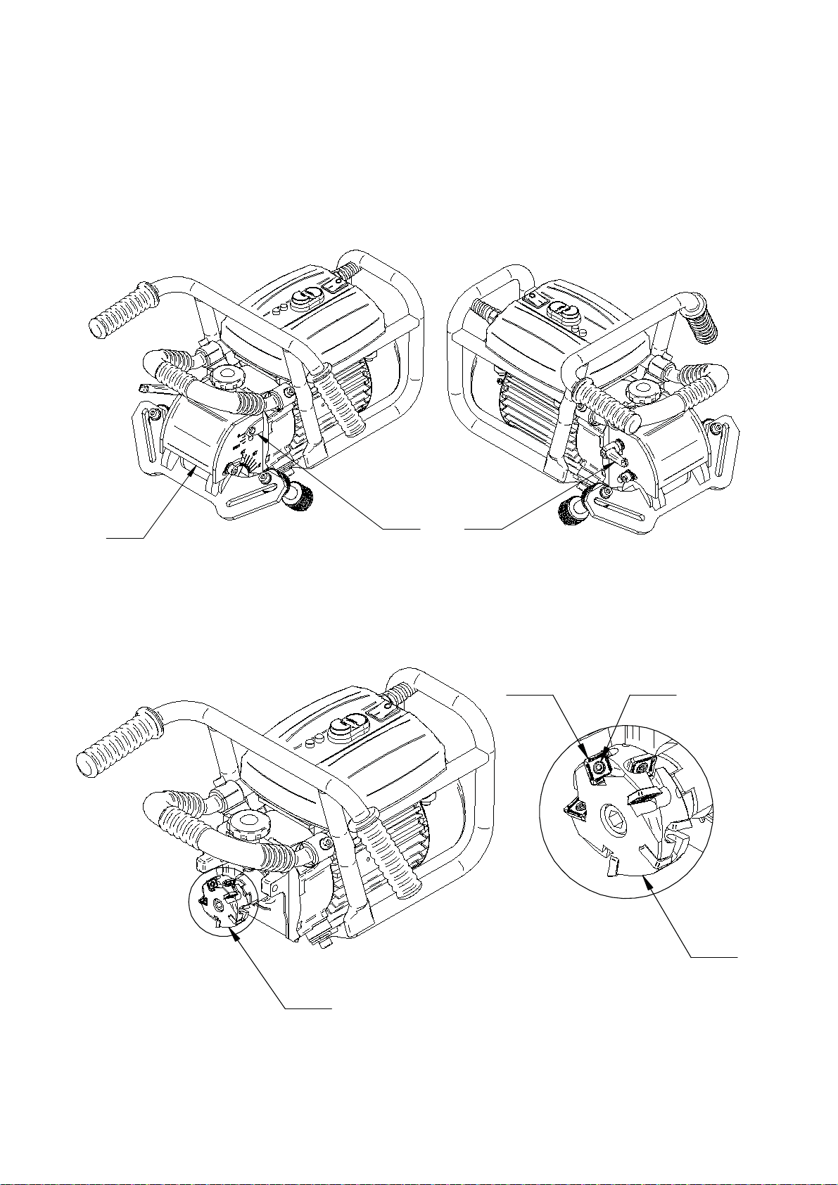
3.6. Replacing cutting inserts
BM-21 Bevelling Machine is equipped with uniform milling head (Figure 8, Item 1), containing
two insert rings, each holding five cutting inserts, for a total of 10 inserts. The inserts can be replaced
or rotated. Perform this work only with power cord unplugged from power socket. To replace or
rotate the insert, unscrew lever (Figure 7, Item 1), remove pitch (Figure 7, Item 2) and remove milling
head cover (Figure 7, Item 3).
3
Figure 7. Dismantling milling head cover Using torx T15 screwdriver, unscrew bolt (Figure 8,
Item 3), remove external insert (Figure 8, Item 2) and clean the socket. Then, place rotated
insert again or replace with new one if all four edges are worn out. To replace insert from
internal ring, remove external insert first.
12
2 3
A
1
Figure 8. Milling Tool
Operator’s Manual – BM-21 Bevelling Machine
A
1:2
1
14
Page 15
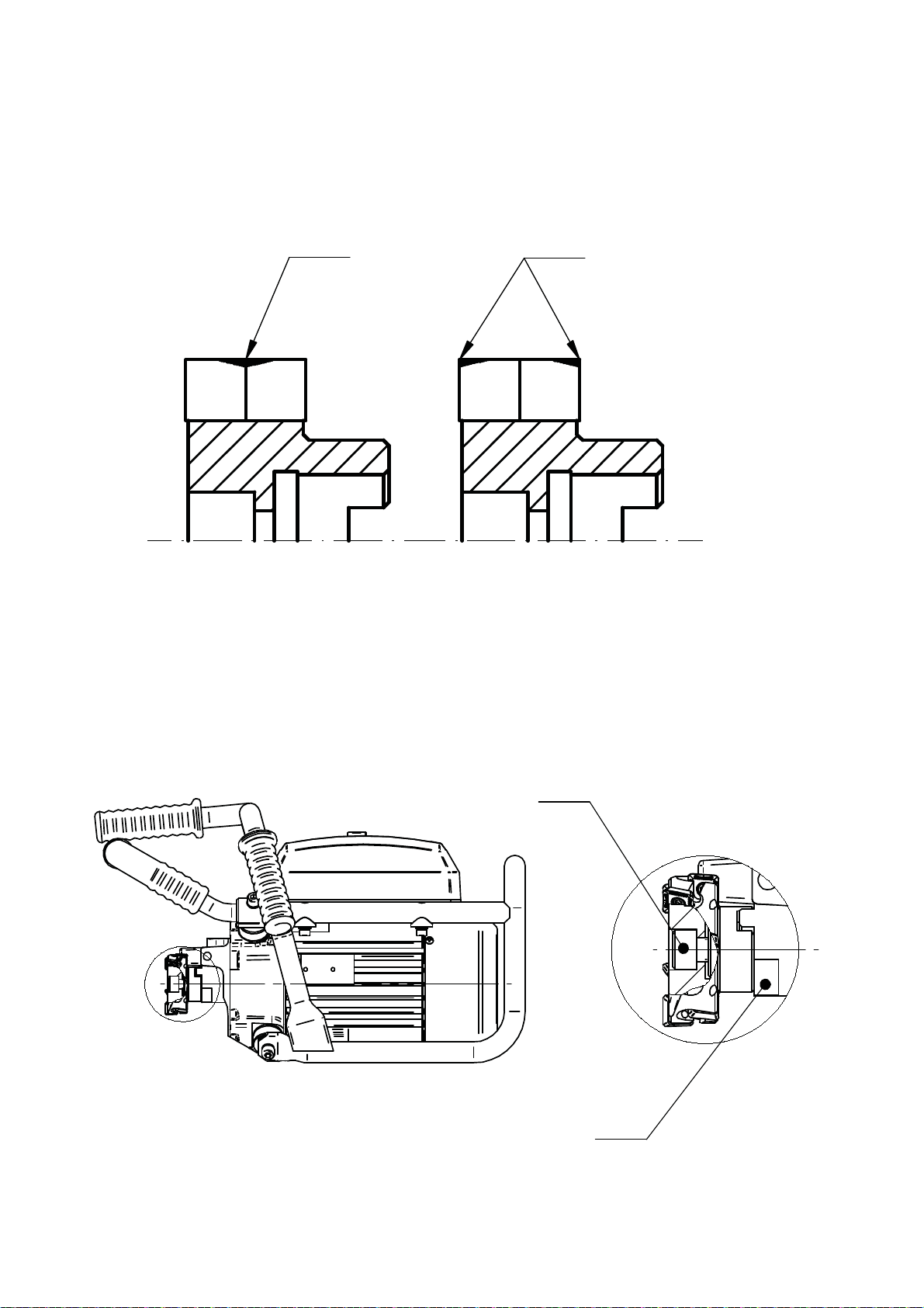
When performing small width bevels, cutting inserts wear only on one, internal corner.
Rotate inserts between rings (Figure 9), to extend the life of inserts.
Worn out corners
Figure 9. Changing cutting inserts between rings
3.7. Replacing milling head
To replace milling head, unscrew lever (Figure 7, Item 1), remove pitch (Figure 7, Item 2) and
remove milling head cover (Figure 7, Item 3). Place size 32 flat key on driving ring (Figure 10, Item 1)
to lock spindle rotation. Then, use size 8 Allen key to unscrew bolt (Figure 10, Item 2) and remove
milling head. Size 32 flat key is not included in standard equipment.
Worn out corners
A
2
1
Figure 10. Replacing milling head
Operator’s Manual – BM-21 Bevelling Machine
A
15
Page 16
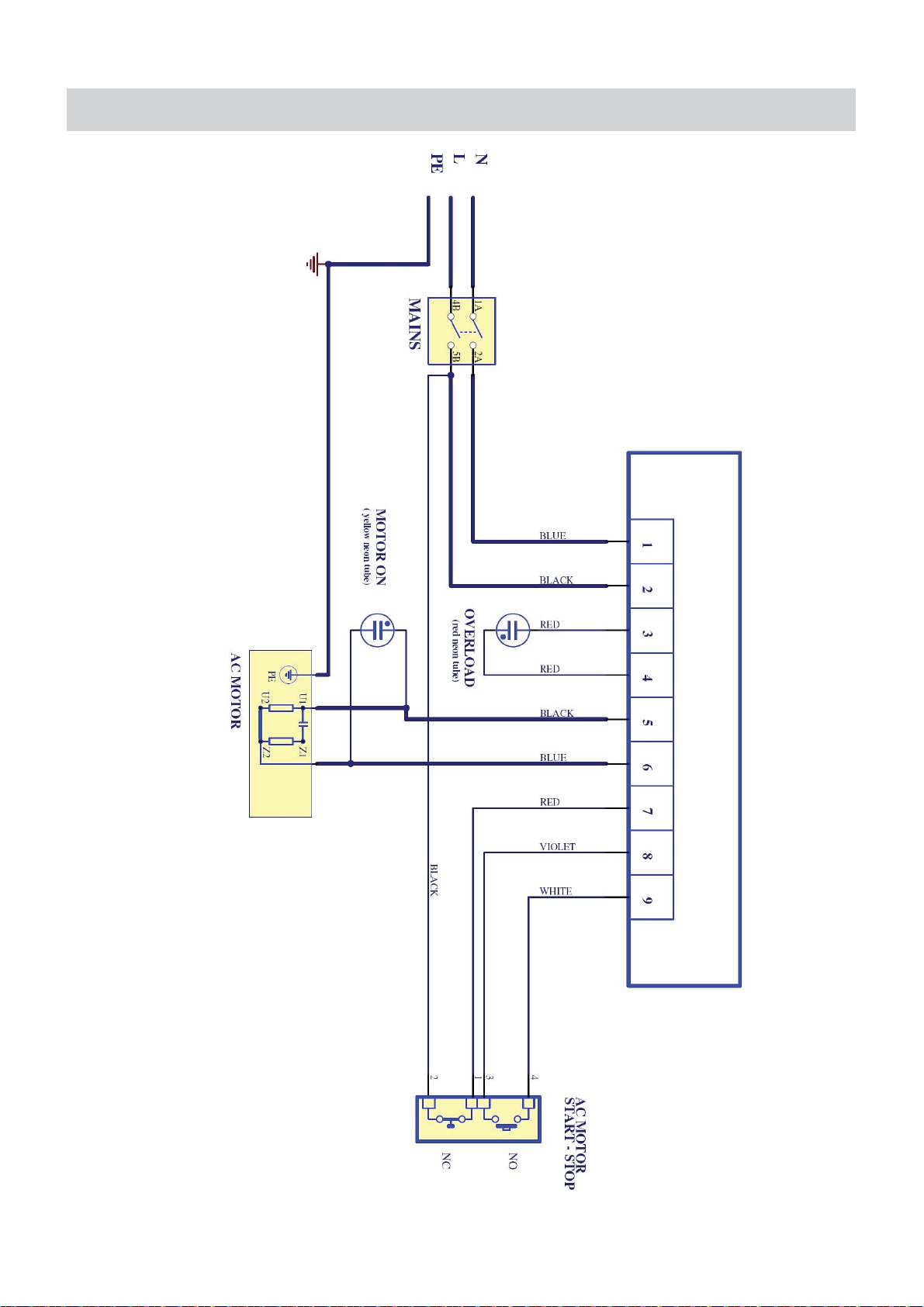
4. WIRING DIAGRAM
Operator’s Manual – BM-21 Bevelling Machine
16
Page 17
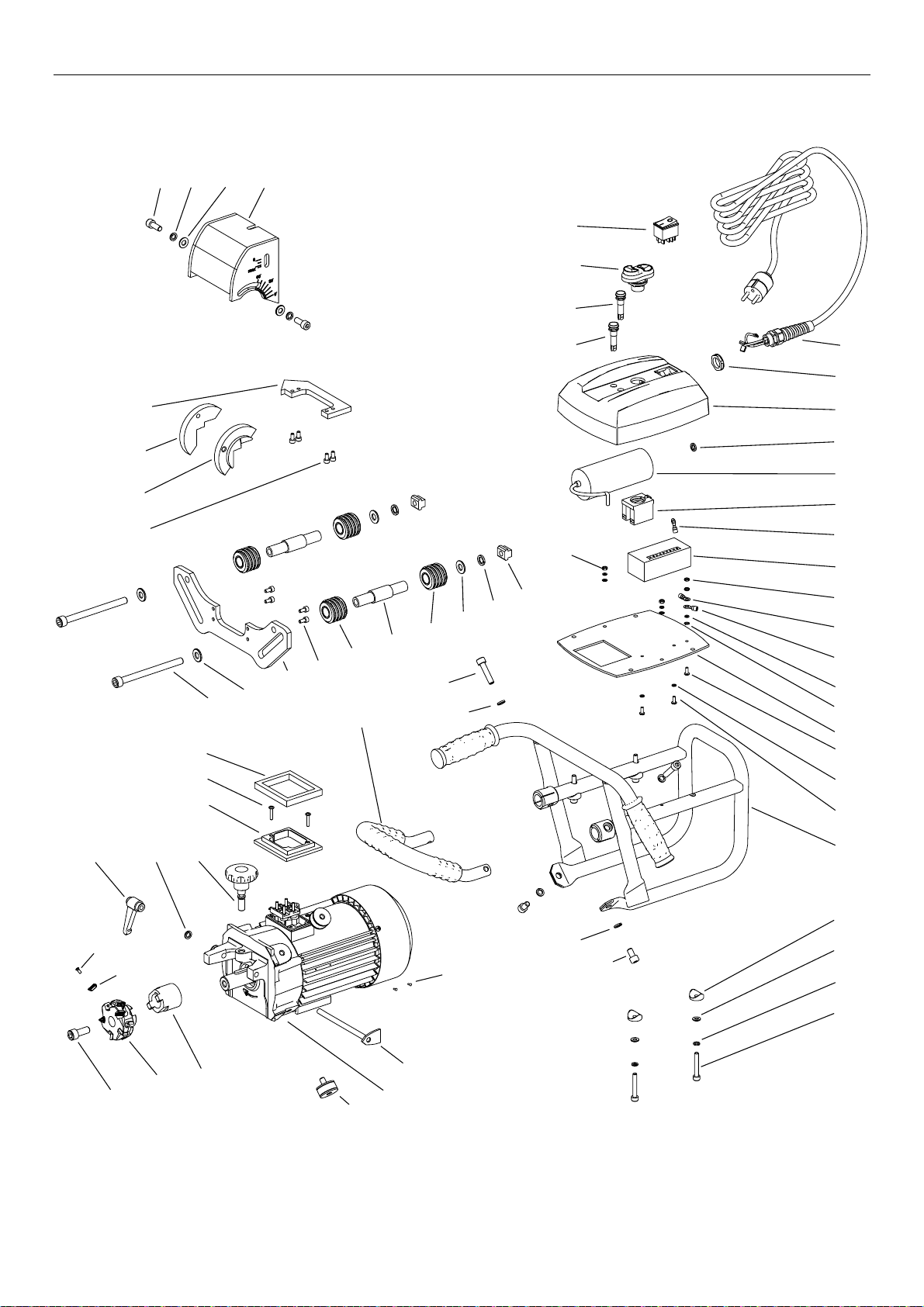
Parts list BM-21S v.1.04
This document is protected by copyrights.
Copying, using, or distributing without permission of PROMOTECH is prohibited. 1
46
59
36
58
51
47
32
35
49
53
13
38
40
38
52
43
43
1
46
28
38
16
29
57
45
15
44
49
56
14
3
38
17
19
23
18
21
22
60
48
5
4
30
31
37
41
39
20
34
54
12
50
11
8
50
12
24
7
9
38
33
10
34
55
6
Page 18

Parts list BM-21S v.1.04
This document is protected by copyrights.
Copying, using, or distributing without permission of PROMOTECH is prohibited. 2
ITEM
PART NUMBER
DESCRIPTION
Qty
1
PWD-0461-17-00-00-0
POWER CORD - 230V
1
1
PWD-0461-17-00-00-1
POWER CORD - 115V
1
1
PWD-0461-17-00-00-2
POWER CORD - 230V (AU)
1
3
SLN-0505-01-00-00-2
MOTOR ASSY - 230V
1
3
SLN-0505-01-00-00-3
MOTOR ASSY - 115V
1
4
ZBI-0461-02-00-00-0
DRIVING RING
1
5
PKT-0461-04-00-00-0
KNOB
1
6
OSL-0461-05-00-00-0
MILLING HEAD COVER
1
7
PRW-0505-02-01-00-0
VERTICAL GUIDE
1
8
PRW-0505-02-02-00-0
HORIZONTAL GUIDE
1
9
OBS-0461-06-03-00-1
GUIDE HOLDER I
1
10
OBS-0461-06-04-00-1
GUIDE HOLDER II
1
11
OSK-0461-06-05-00-0
PIVOT
2
12
RLK-0505-02-03-00-0
ROLLER
4
13
RMK-0461-07-00-00-0
FRAME
1
14
RKJ-0461-08-00-00-0
FRONT HANDLE
1
15
MDL-0461-09-02-00-0
ELECTRONIC MODULE COMPLETE - 230V
1
15
MDL-0461-09-02-00-1
ELECTRONIC MODULE COMPLETE - 115V
1
16
PLY-0461-09-03-00-0
BOTTOM PLATE
1
17
PKR-0461-09-04-00-0
CONTROLLER HOUSING COVER
1
18
KON-0461-09-10-00-0
RED LAMP
1
19
KON-0461-09-11-00-0
YELLOW LAMP
1
20
WSK-0461-11-00-00-0
PENETRATION INDICATOR
1
21
LCZ-0461-12-00-00-0
LINK
1
22
USZ-0461-13-00-00-0
RUBBER SEAL
1
23
WBR-0461-14-00-00-0
DAMPER
4
24
GLW-0461-03-00-00-0
MILLING HEAD WITH BOLTS
1
28
NKR-000014
HEX. NUT M4
2
29
NKR-000032
NUT SHORT M4
2
30
NKR-000082
T-NUT
2
31
NIT-000010
ROUND HEAD RIVET 2x6
2
32
PDK-000021
ROUND WASHER 6,4
4
33
PDK-000022
ROUND WASHER 8,4
3
34
PDK-000026
ROUND WASHER 10,5
4
35
PDK-000175
SADDLE WASHER
4
36
PDK-000060
EXTERNAL TOOTH SPRING WASHER 4,3
6
37
PDK-000052
SPRING WASHER 10,2
2
38
PDK-000051
SPRING WASHER 8,2
8
39
PLY-000282
CUTTING INSERT
10
40
RKJ-000010
HANDLEVER
1
41
SRB-000311
MOUNTING BOLT
10
43
WKR-000183
SCREW M4x10 PHCRMS
4
44
KND-000114
CAPACITOR 30uF - 240V
1
44
KND-000115
CAPACITOR 80uF - 110V
1
45
NKR-000040
STRAIN RELIEF NUT
1
46
PDK-000043
SPRING WASHER 4,1
6
47
PDK-000046
SPRING WASHER 6,1
4
48
PNK-000013
POWER SWITCH
1
49
PRC-000007
MOTOR ON/OFF SWITCH
1
50
SRB-000075
HEX SOCKET BOLT M5x10
8
51
SRB-000124
HEX. SOCKET BOLT M6x40
4
Page 19

Parts list BM-21S v.1.04
This document is protected by copyrights.
Copying, using, or distributing without permission of PROMOTECH is prohibited. 3
ITEM
PART NUMBER
DESCRIPTION
Qty
52
SRB-000141
HEX. SOCKET BOLT M8x14
2
53
SRB-000156
HEX. SOCKET BOLT M8x35
2
54
SRB-000046
HEX. SOCKET BOLT M10x25
1
55
SRB-000309
HEX SOCKET BOLT M10x120
2
56
SRB-000148
HEX. SOCKET BOLT M8x20
2
57
WZK-0461-09-07-00-0
STOP BUTTON WIRE SET
1
58
WZK-0461-09-08-00-0
CONTROLLER PLATE GROUNDING WIRE
1
59
WZK-0461-09-09-00-0
MOTOR GROUNDING WIRE
1
60
WKR-000446
CROSS RECESSED SCREW M4x20
2
61*
SKR-0461-15-00-00-0
METAL BOX
1
62*
KLC-000011
ALLEN KEY s=8
1
65*
KLC-0461-16-00-00-0
ALLEN KEY s=6 -mod.
1
66*
WKT-000005
TORX PLUS SCREWDRIVER T15Px100
1
67*
KLC-000032
FLAT KEY s=12
1
68*
KLC-000007
ALLEN KEY s=4
1
69*
SMR-000005
GREASE FOR SCREWS
1
70*
OLJ-0505-05-00-00-0
OIL FOR STEEL
0,5kg
71*
OLJ-0505-06-00-00-0
OIL FOR STEEL
1kg
72*
OLJ-0505-07-00-00-0
OIL FOR STEEL
5kg
73*
OLJ-0505-08-00-00-0
OIL FOR STEEL
30kg
*- not shown on the drawing
Page 20
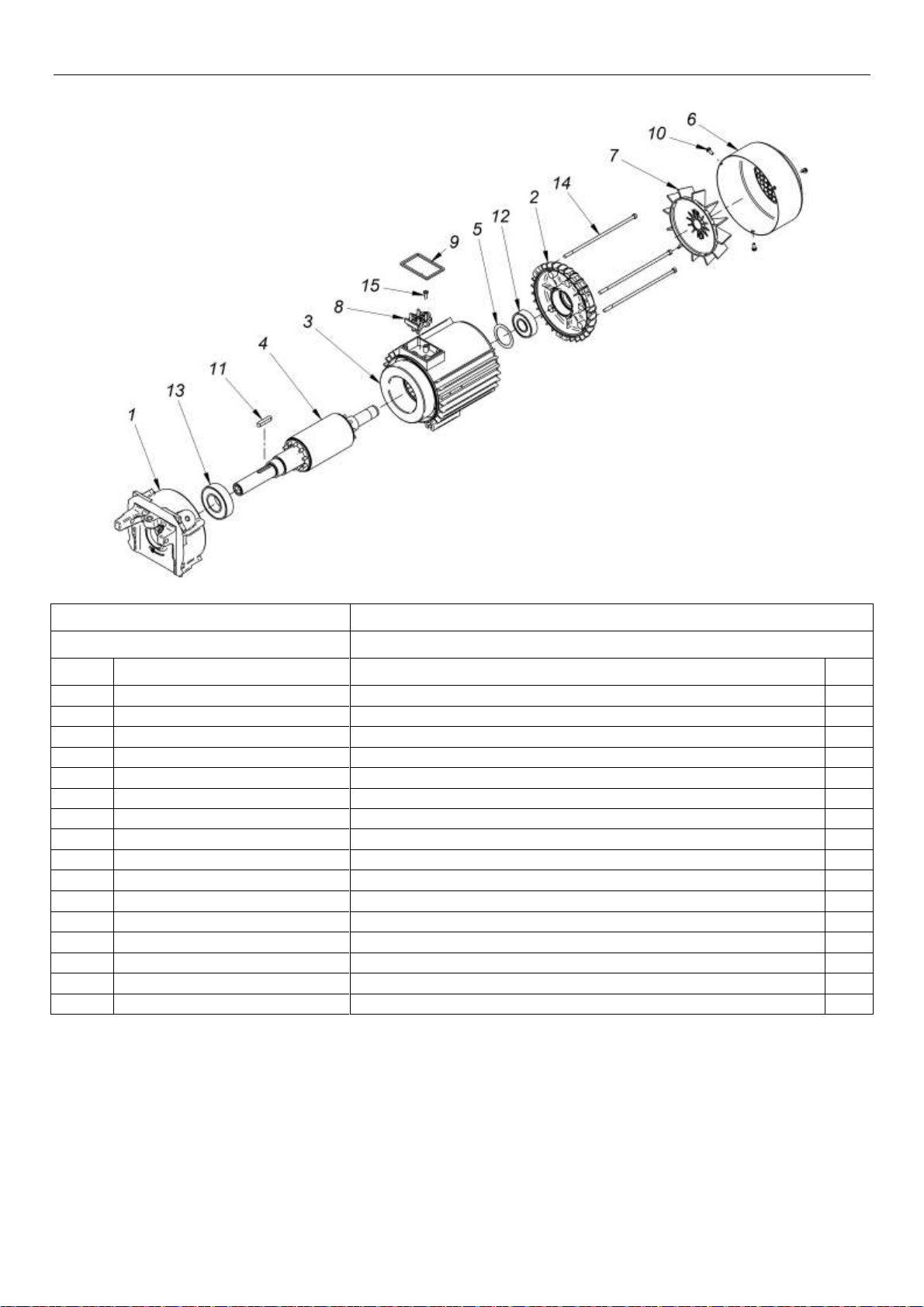
Parts list BM-21S v.1.04
This document is protected by copyrights.
Copying, using, or distributing without permission of PROMOTECH is prohibited. 4
SLN-0505-01-00-00-2
MOTOR ASSY - 230V
SLN-0505-01-00-00-3
MOTOR ASSY - 115V
ITEM
PART NUMBER
DESCRIPTION
Qty
1
TRC-0461-01-02-00-2
BEARING DISK N
1
2
TRC-000024
BEARING DISK P
1
3
KDL-000003
STATOR BODY - 230V
1
3
KDL-000004
STATOR BODY - 110V
1
4
WRN-000051
ROTOR
1
5
PDK-000195
CLEARANCE REMOVAL SPRING WASHER
1
6
OSL-000193
FAN COVER
1
7
WNT-000008
FAN
1
8
TBL-000032
4-TERMINAL PLATE
1
9
USZ-000030
SEAL no.4
1
10
WKR-000466
SELF-TAPPING SCREW M4x8
3
11
WPS-000015
PIN A6x6x32
1
12
LOZ-000139
BALL BEARING 6204 2Z C3
1
13
LOZ-000140
BALL BEARING 6206 2Z CM
1
14
SRB-000349
DRAWBOLT E/M5x168
3
15
WKR-000467
SELF-TAPPING SCREW M4x12
1
 Loading...