

Page 1
INDUSTRIAL TOOLS
OPERATOR’S MANUAL
B
B
M
M--1166
BEVELLING MACHINE
BM16
BEVELLING MACHINE
OPERATOR’S MANUAL
BEFORE USE, ENSURE EVERYONE USING THIS MACHINE READS AND UNDERSTANDS
ALL SAFETY AND OPERATING INSTRUCTIONS IN THIS MANUAL .
Serial #............................................ Date of Purchase............................
Page 2

TRADEMASTER BM16 BEVELLING MACHINE
LIMITED WARRANTY
Industrial Tool & Machinery Sales (hereinafter referred to as ITMS) will, within twelve (12)
months from the original date of purchase, repair or replace any goods found to be defective
in materials or workmanship.
This warranty is void if the item has been damaged by accident, neglect, improper service or
other causes not arising out of defects in materials or workmanship. This warranty does not
apply to machines and/or components which have been altered, changed, or modified in any
way, or subjected to overloading or use beyond recommended capacities and specifications.
Worn componentry due to normal wear and tear is not a warranty claim. Goods returned
defective shall be returned prepaid freight to ITMS or agreed repair agent, which shall be the
buyer’s sole and exclusive remedy for defective goods. ITMS accepts no additional liability
pursuant to this guarantee for the costs of travelling or transportation of the product or parts to
and from ITMS or the service agent or dealer, such costs are not included in this warranty.
Our goods come with guarantees which cannot be excluded under the Australian Consumer
Law. You are entitled to replacement or refund for a major failure and to compensation
for other reasonably foreseeable loss or damage. You are also entitled to have the goods
repaired or replaced if the goods fail to be of acceptable quality and the failure does not
amount to a major failure.
THE MANUFACTURER RESERVES THE RIGHT TO MAKE IMPROVEMENTS AND
MODIFICATIONS TO DESIGN WITHOUT PRIOR NOTICE.
PRODUCTS IMPORTED AND DISTRIBUTED NATIONALLY BY:
INDUSTRIAL TOOL & MACHINERY SALES
18 BUSINESS ST, YATALA QLD 4207
T: 07 3287 1114 E: [email protected]
F: 07 3287 1115 W: www.industrialtool.com.au
TABLE OF CONTENTS
1.GENERAL INFORMATION ............................................................................................3
1.1.Application ...................................................................................................................3
1.2.Technical data .............................................................................................................3
1.3.Equipment included .....................................................................................................4
1.4.Dimensions ..................................................................................................................4
1.5.Design .........................................................................................................................5
2.SAFETY PRECAUTIONS...............................................................................................6
3.STARTUP AND OPERATION ........................................................................................8
3.1.Installing and removing the milling head .....................................................................8
3.2.Adjusting the bevel parameters .................................................................................10
3.3.Adjusting the guide for bevelling with radius .............................................................11
3.4.Preparing
3.5.Operating
3.6.Replacing the cutting inserts .....................................................................................13
3.7.Replacing the roller....................................................................................................14
3.8.Replacing the brushes ...............................................................................................15
4.ACCESSORIES............................................................................................................16
4.1.Guide for bevelling pipes
4.2.Anti-scratch guide sticker
4.3.Worktable fixture........................................................................................................18
4.4.Radius insert positioner .............................................................................................22
4.5.Milling tools ................................................................................................................23
5.SPARE AND WEARING PARTS..................................................................................23
6.WIRING DIAGRAM ......................................................................................................24
2
7.PARTS LIST
...................................................................................................................11
...................................................................................................................12
...........................................................................................16
..........................................................................................18
.................................................................................................................25
Page 3
GENERAL INFORMATION
BM-16
1~ 220–240 V, 50–60 Hz
1~ 110–120 V, 50–60 Hz
Power
2200 W
Rotational speed (without load)
1800–5850 rpm
Protection level
IP 20
Protection class
II
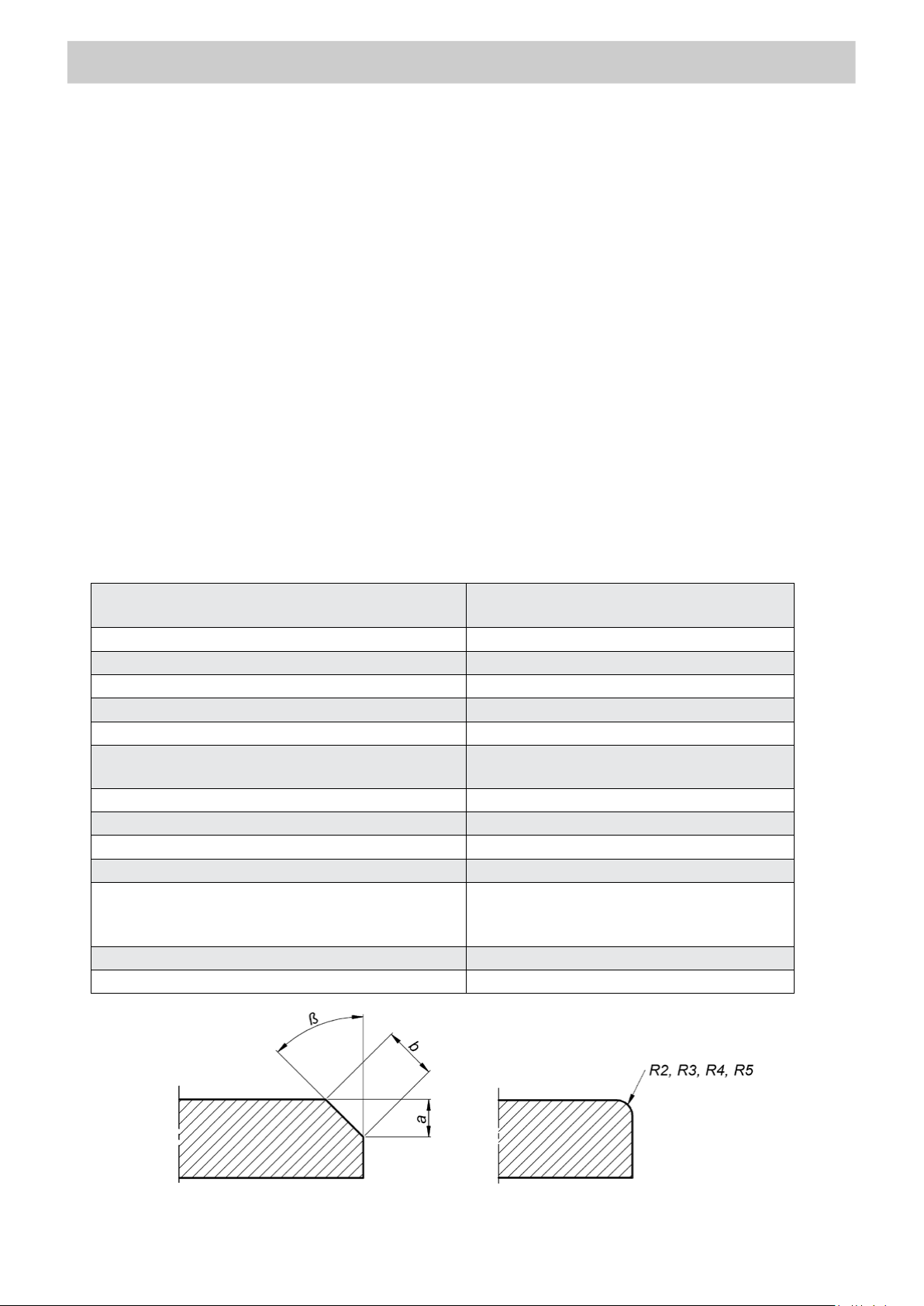
Maximum bevel width (b)
16 mm (0.63’’, Fig. 1)
Bevel angle (ß, depends on the
milling head used)
22.5°, 30°, 37.5°, 45°, 50°, 55°, 60°, 65°
(Fig. 1)
Minimum workpiece thickness for bevelling
1.5 mm (0.06’’)
Minimum hole diameter
40 mm (1.57’’)
Edge radius
2 mm, 3 mm, 4 mm, 5 mm (Fig. 1)
Noise level
More than 70 dB
2.3 m/s2 (7.5 ft/s2)
break s during work.
Required ambient temperature
0–40°C (34–104°F)
Weight (without milling head)
10 kg (22 lbs)
1. GENERAL INFORMATION
1.1. Application
The BM-16 is a bevelling machine designed to mill edges of plates and pipes made
of steel, aluminum alloys, brass, or plastics.
Depending on the milling head used the machine allows bevelling workpieces
with a thickness of at least 1.5 mm (0.06’’) at the angle of 22.5°, 30°, 37.5°, 45°, 50°,
55°, 60°, or 65° to the maximum bevel width of 16 mm (0.63’’). A radius m illing h ead
allows bevelling with a radi us of 2, 3, 4, or 5 mm. The minimum diameter of a hole to
be machined is 40 mm (1.57’’).
An optional guide allows bevelling pipes, sticker protects aluminum workpieces
against scratches, and worktable fixture allows bevel ling flat bars.
1.2. Technical data
Voltage
Vibration level
Machine harmful for health. Take periodic
Fig. 1. Bevel dimensions
3
Page 4
BM-16
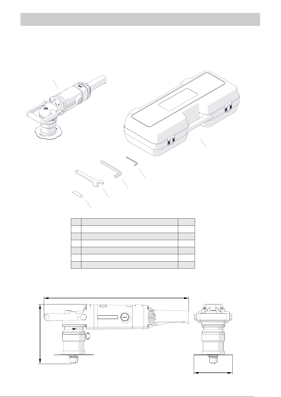
1
Bevelling machine (without milling head)
1 unit
2
Plastic box
1 unit
3
5 mm hex wrench
1 unit
4
14 mm hex wrench
1 unit
5
32 mm flat wrench
1 unit
6
Grease for screws (5 g, 0.17 oz)
1 unit
–
Operator’s Manual
1 unit
1
3 4 5
2
6
585 mm (23’’)
241 mm (9.4’’)
156 mm (6.1’’)
1.3. Equipment included
GENERAL INFORMATION
1.4. Dimensions
4
Page 5
GENERAL INFORMATION
BM-16
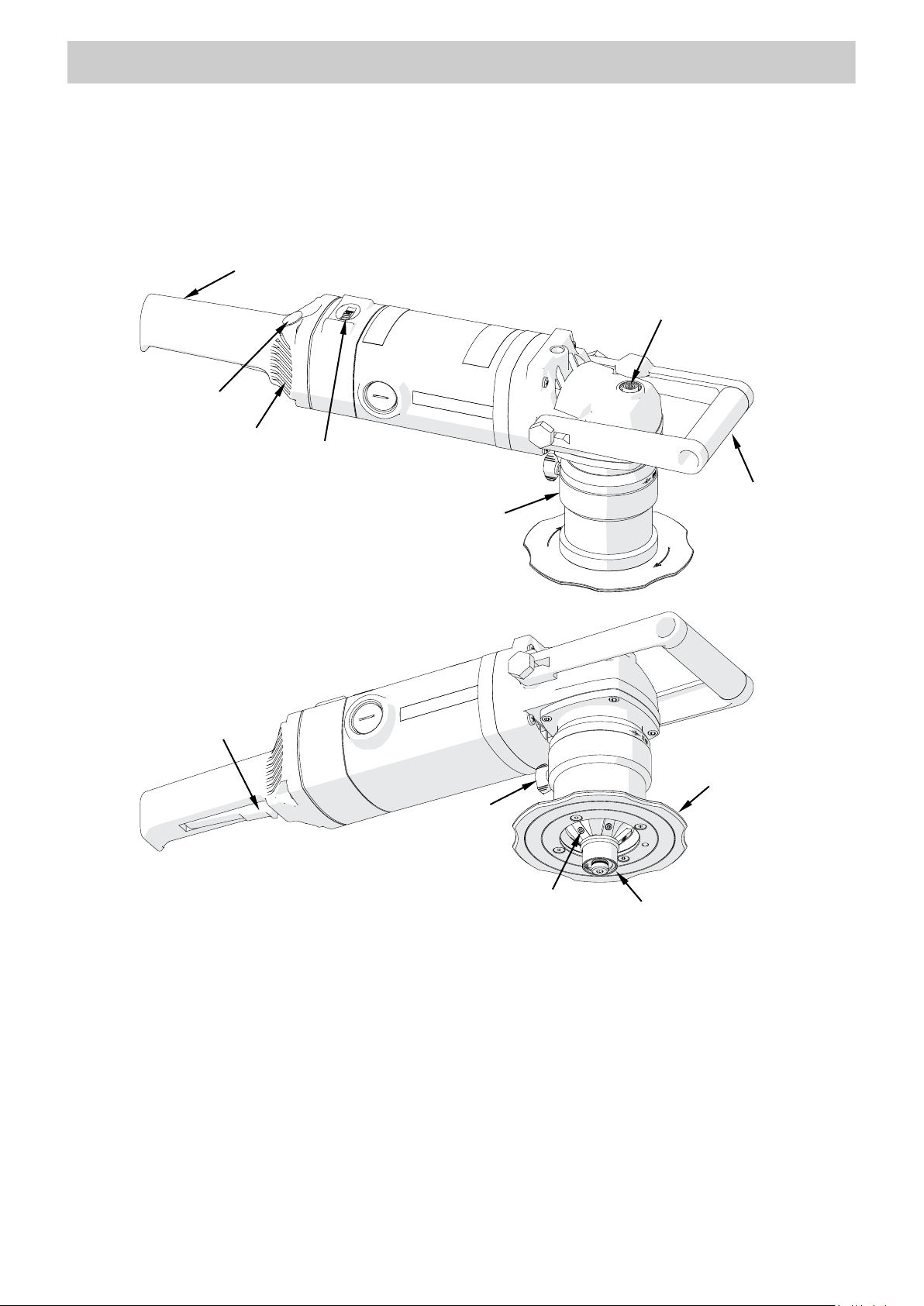
Speed adjustment dial
Handle
Handle
Spindle lock button
Switch lock
ON/OFF switch
Guide
Clamping
Milling head
Guiding roller
Sleeve
Air vents
1.5. Design
screw
5
Page 6

SAFETY PRECAUTIONS
BM-16
2. SAFETY PRECAUTIONS
1. Before starting, read this Operator’s Manual and complete proper occupational
safety and health training.
2. Use the machine only in applications specified in this Operator’s Manual.
3. The
4. The specifications of the power source must conform to those specified on the
5. Never carry the machine by the cord and never pull the cord because this may
6. Untrained bystanders must not be present near the machine.
7. Before starting, ensure the correct condition of the machine, power source, power
8. Keep the machine dry, and never expose it to rain, snow, or frost.
9. Keep the work area well lit, clean, and free of obstacles.
machine must be complete and all parts must be genuine and ful l y functional.
rating plate.
damage it and result in electric shock.
cord, plug, control components, and milling tools.
10. Never use near flammable liquids or gases, or in explosive environments.
11. Use only tools specified in this Operator ’ s Manual.
12. Never use tools that are dull or damaged.
13. Install the cutting inserts and milling head securely. Remove adjusting keys and
wrenches
14. Never use the machine in upside down position with the milling head facing up.
15. If the cutting edge of the insert is worn, rotate the insert in the socket by 90° or
180° or, if all possible to use edges are worn, replace with a new insert specified in
this Operator’s Manual.
16. Before every use, inspect the machine to ensure it is not damaged. Check whether
any part is cracked or improperly fitted. Make sure to maintain proper conditions
that may affect the operation of the machi ne.
17. Always use eye and hearing protection, non-skid footwear, and protective clothing
during work. Do not wear loose clothing.
18. Never use the spindle lock button when operating the machine or removing the
from the work area before connecting the machine to the power sourc e.
milling head because this may damage the machine.
19. Do not touch moving parts or metal chips formed during milling. Prevent objects
from being caught in movi ng parts .
6
Page 7

SAFETY PRECAUTIONS
BM-16
20. After every use, remove metal chips from the machine, especially from the milling
head. Never remove chips with bare hands. Clean
the machine with a c otton cloth
without using any agents.
21. Cover steel parts with a thin anti-corrosion coating to protect them from rust when
not in use for any extended period.
22. Maintain the machine and install/remove parts and tools only when the machine
is unplugged from the power source.
23. Repair only in a service center appointed by the seller.
24. If the machine falls from any height, is wet, or has any other damage that could
affect the technical state of the machine, stop the work and promptly
send the
machine to the service center for inspection and repair.
25. Remove
from the worksite and store in a secure and dry place when not in use.
7
Page 8
STARTUP AND OPERATION
BM-16
2 1 3 6 7 5 8
CORRECT
INCORRECT
INCORRECT
Washers
Distance
4
3. STARTUP AND OPERATION
3.1. Installing and removing the milling head
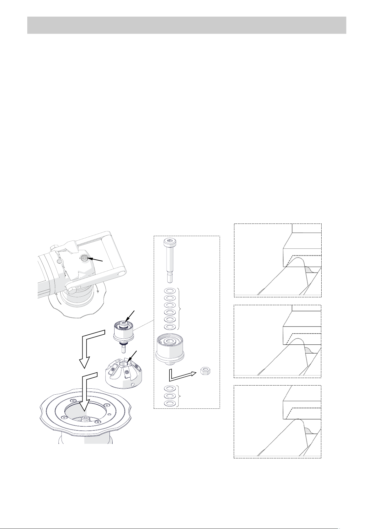
Unplug the machine from the power source. To install the milling head, place it on the
spindle (1, Fig. 2), and then press and hold the spindle lock button (2) and tighten the
head with the 14 mm hex wrench (3). Next, remove the nut (4) and assemble the roller
with
the pivot pin by using washers (5), and then place the roll er on the milli ng head ( 6),
press and hold the button (2), and tighten the roller with the 5 mm hex wrench (7).
Use such a number of 0.5-mm and 0.1-mm washers to keep a little gap between the
roller and cutting inserts (8). The number of washers needed depends on the milling
head used.
unused
washers
(collision
between
roller and
cutting insert)
✓
(too large gap
between roller
and cutting
insert)
8
Fig. 2. Installing the milling head
Page 9
STARTUP AND OPERATION
BM-16
7
2 1 6 9 8
3
5
4
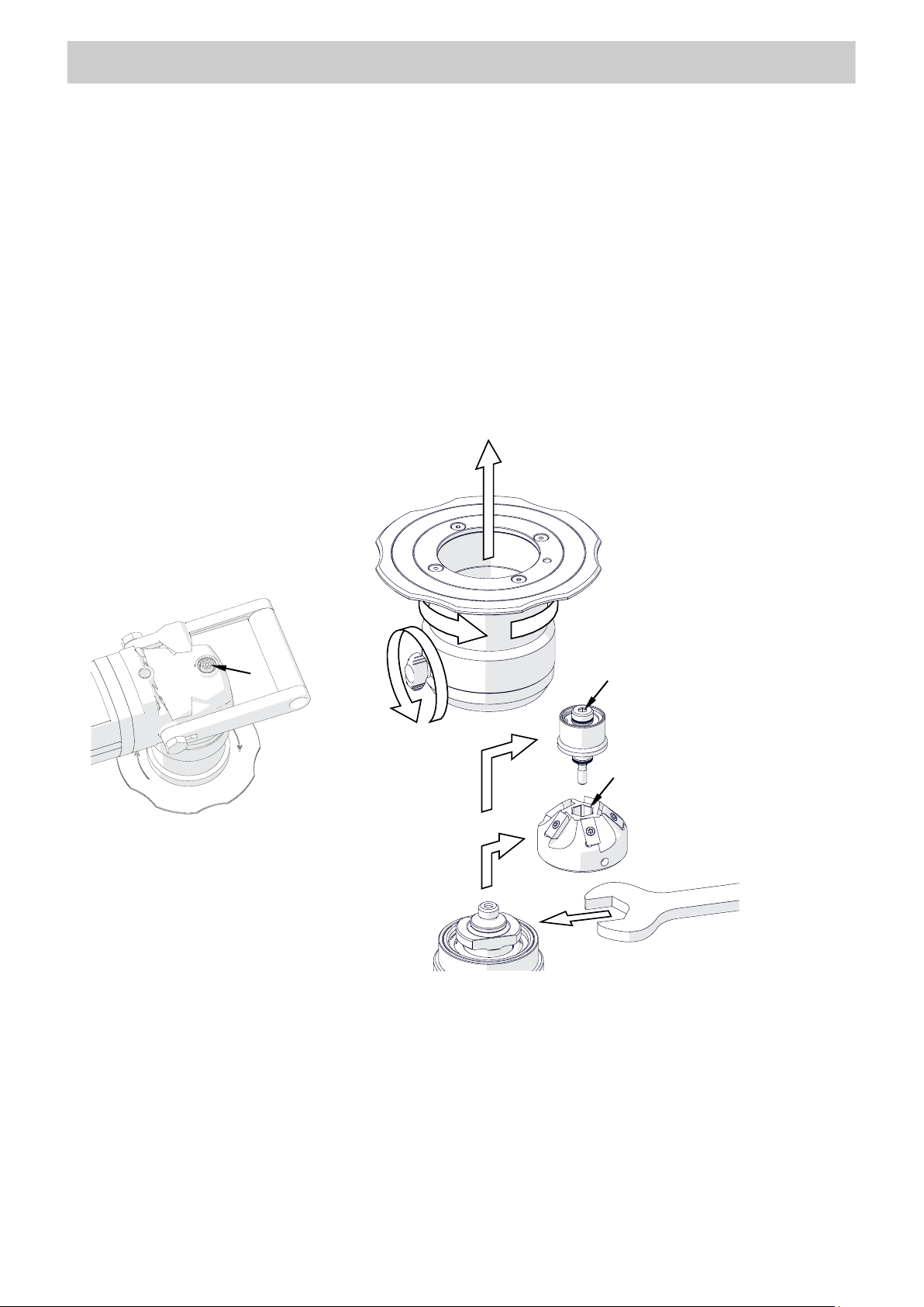
Adjust the gap between the rol l er and t he cutt ing inserts every time you replace the
milling head. Place all unused washers
between the pivot pin and the r ol ler .
To remove the milling head, loosen the clamping screw (1, Fig. 3), and then
unscrew the sleeve (2) and remove it (3). Next, press and hold the button (4), and
then use the 5 mm hex wrench (5) to unscrew the roller, and remove it (6). Lock the
spindle with the 32 mm flat wrench (7, do not use the spindle lock button 4 because
this may damage the machine), and then use the 14 mm hex wrench to unscrew the
head (8), and remove it (9).
Fig. 3. Removing the milling head
9
Page 10
STARTUP AND OPERATION
BM-16
Height ‘a’ [mm]
Width ‘b’ [mm]
1
0.7
1.4
1.6
2.3
2.9
3.7
2
1.2
2.0
2.8
3.1
4.0
4.9
6.1
3
1.1
2.3
3.2
4.2
4.7
5.8
6.9
8.5
4
2.3
3.5
4.5
5.7
6.2
7.5
8.9
10.8
5
3.4
4.6
5.7
7.1
7.8
9.3
10.9
13.2
6
4.5
5.8
7.0
8.5
9.3
11.0
12.9
15.5
7
5.6
6.9
8.3
9.9
10.9
12.8
14.9 8
6.7
8.1
9.5
11.3
12.4
14.5
9
7.7
9.3
10.8
12.7
14.0
16.3
10
8.8
10.4
12.1
14.1
15.6
11
9.9
11.6
13.3
15.6
11.5
10.4
12.2
13.9
16.3
12
11.0
12.7
14.6
13
12.1
13.9
15.8
1 2 3
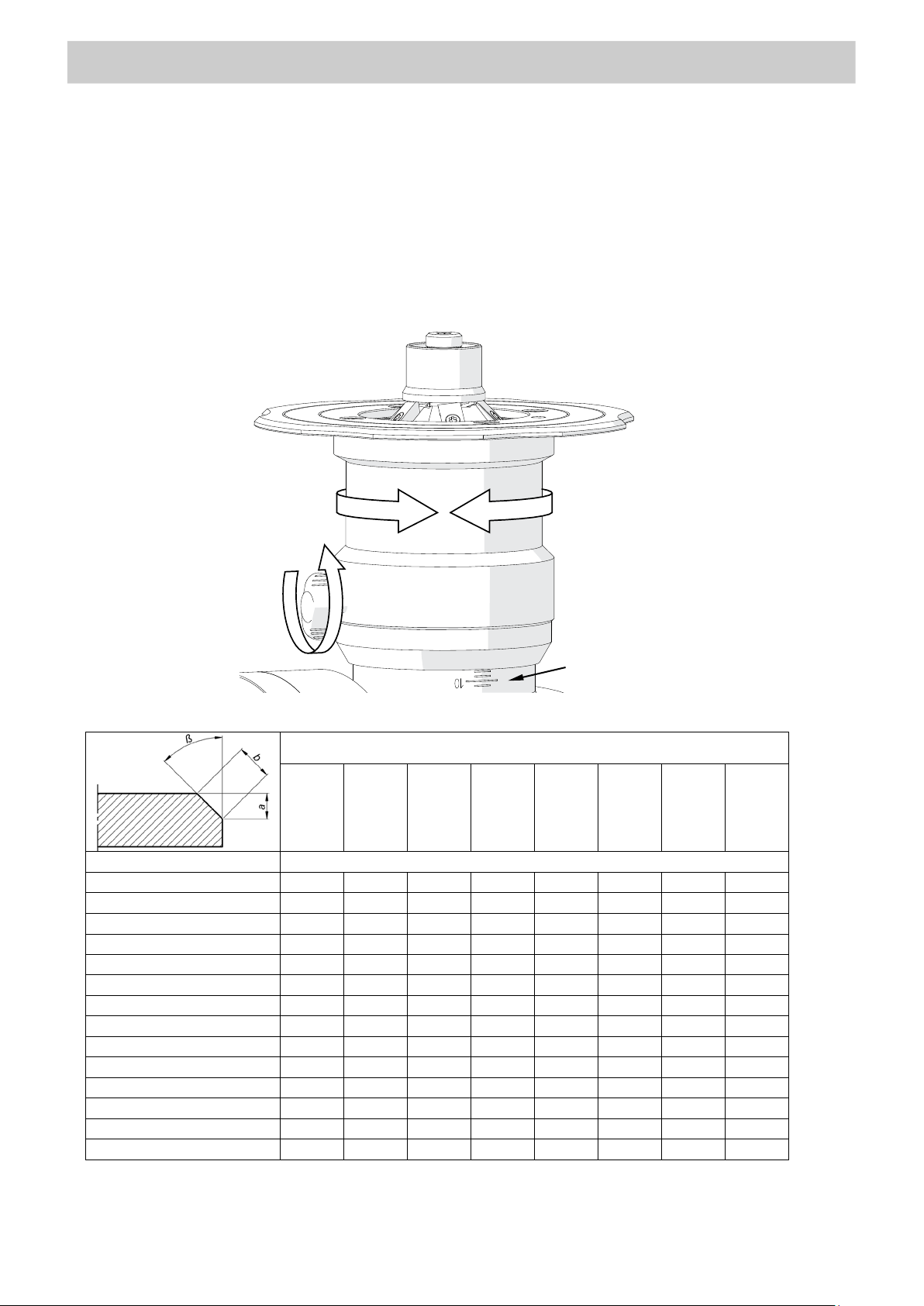
3.2. Adjusting the bevel parameters
Unplug the machine from the power source. Next, loosen the clamping screw (1,
Fig. 4), rotate the sleeve (2) so that the scale (3) shows the required bevel height ‘a’
(Tab. 1), and then re-tighten the screw.
Fig. 4. Adjusting the bevel parameters
Milling head
22.5°
30° 37.5°
45°
50°
55°
60°
65°
10
Tab. 1. Relation between bevel width and height of the available milling head s
Page 11
STARTUP AND OPERATION
BM-16
Material type
Rotational speed
Setting 6
(5850 rpm)
Settings 3–5
(3100–4500 rpm)
2
1
3.3. Adjusting the guide for bevelling with radius
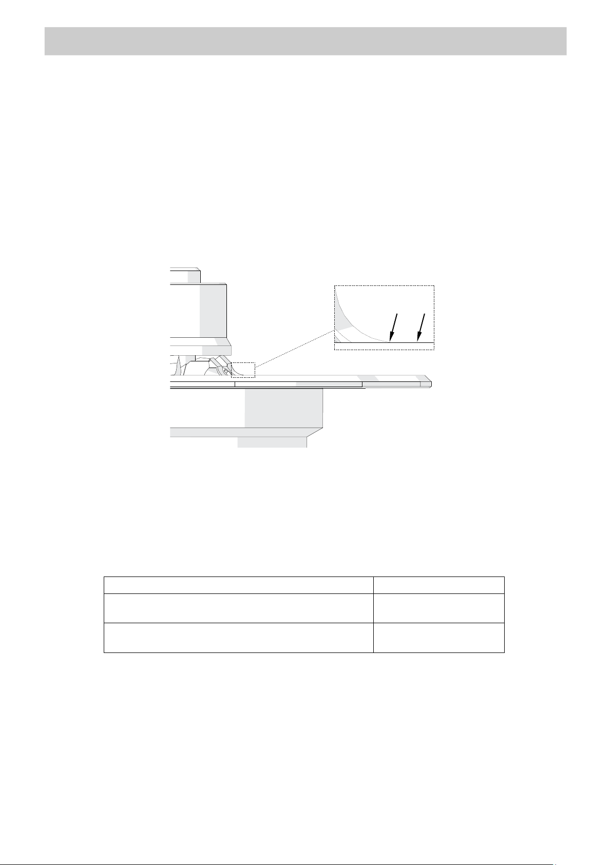
Unplug the machine from the power source, and then in the manner described before
loosen the clamping screw and rotate the sleeve to set the surface (1, Fig. 5) on the
same level as the radial cutting edge (2). You can also use an optional radius insert
positioner to set the guide properly. Next, re-tighten the clamping screw, and then
bevel a test edge and readjust the position of the guide if necessary.
Fig. 5. Guide adjusted for bevelling with radius
3.4. Preparing
Install a milling head with cutting inserts, and set the required bevel parameters.
Then, use the speed adjustment dial to set the speed matching to the type of the
workpiece (Tab. 2).
Aluminum, brass, plastics
Structural steel of standard quality, quality steel
Tab. 2. Recommended rotational speeds
The speed adjustment dial allows continuous control of the rotational speed in
the range of 1800–5850 rpm (settings 1–6). The relations between the setting and
speed are as follows: setting 1 – 1800 rpm, 2 – 2400 rpm, 3 – 3100 rpm, 4 – 3800 rpm,
5 – 4500 rpm, 6 – 5850 rpm.
When usin g structural steel of standard quality or quality steel, set the speed to
setting 4 and decrease the speed if intensive sparking occurs during work.
11
Page 12
STARTUP AND OPERATION
BM-16
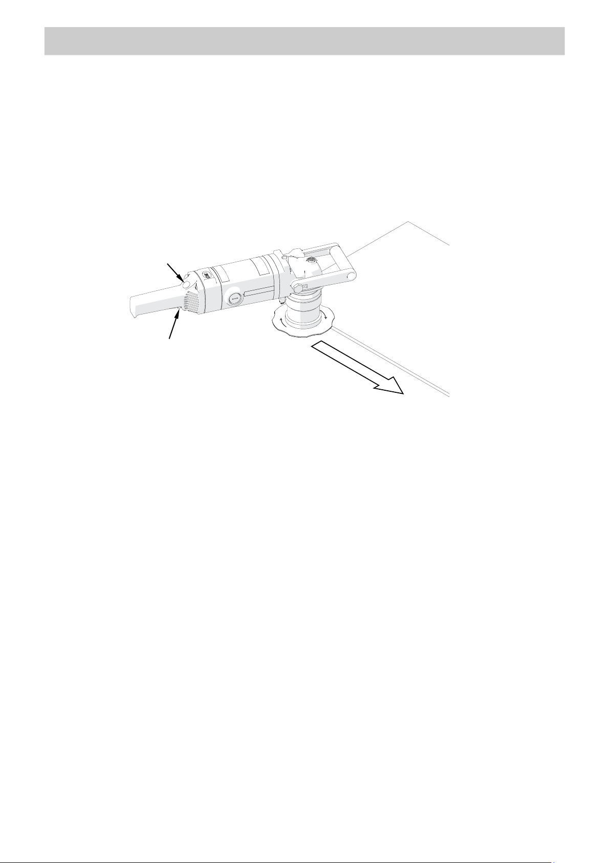
Feed direction
Switch lock
ON/OFF switch
3.5. Operating
Connect the machine to the power source and place the machine on the left side of
the workpiece in the manner shown in Fig. 6. The milling head must not be in contact
with the workpiece. The workpiece must be balanced and well fixed.
Fig. 6. Machine placed on a plate and proper feed direction
To start the motor, press and hold the switch lock and the ON/OFF switch, and
then release the lock. Wait a few seconds until the machine reaches the required
rotational speed, press the machine to the workpiece with both hands, and slowly
slide toward the edge until the tool starts cutting into the metal. Operate according to
the counter-rotation, by sliding the machine from left to right. The rotation direction of
the milling head is indicated by the arrow on the guide.
Start with making small bevels (3–4 mm, 0.12–0.16’’) and increase the bevel width
with experience. Bevel in at least two or three passes. The bevel width should be set
to a value that will allow the feed of one meter per minute without much effort.
If the machine becomes overloaded, for instance when the bevel width is too
large for the material being machined or when the cutting inserts are dull, the motor
will automatically stop. However, prevent the motor from overloading by machining
hard materials in multiple passes and replacing the inserts before they become dull.
Additionally, take periodic breaks during work, and keep the air vents unclogged to
prevent the motor from over heati ng as this may lead to damage of the windings.
After the work is finished, turn off the motor by releasing the ON/OFF switch, wait
until the rotation stops, and unpl ug t he machine from the power source.
Clean the machine with a cotton cloth without using any agents.
12
Page 13
ACCESSORIES
BM-16
3
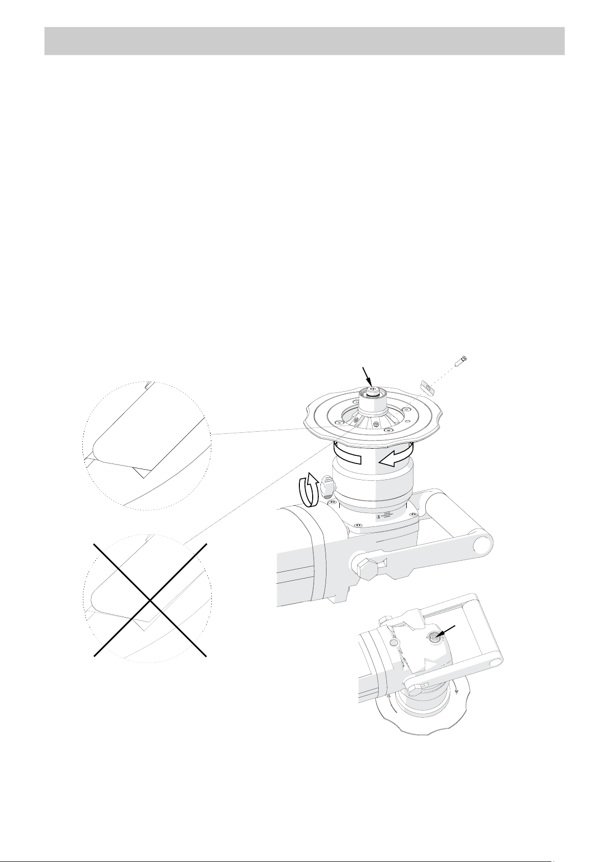
1
2 4 7
6
5
INCORRECT
CORRECT
3.6. Replacing the cutting inserts
Unplug the machine from the power source, and place the machine upside down.
Next, loosen the clamping screw (1, Fig. 7) to access the milling head, and lower the
sleeve
as far as possible by rotating it to the right (2). Then, use the screwdriver supplied
with the milling head to unscrew the screw (3), and remove the cutting insert (4). Clean
the socket, and then rotate the insert and install again or replace with a new one
if all
possible to use edges are worn. Next, push and tighten the insert. The entire bottom
of the insert must be in full contact with the surface of the socket (5).
Before replacing the cutting inserts of the radius milling head, press and hold the
spindle lock button 6 and loosen the guiding roller with the 5 mm hex wren ch (7).
Fig. 7. Replacing the cutting inserts
Clean the threads once a week and, if necessary, grease the fixing screws for inserts
with an agent (for instance copper paste) that will prevent the screws from blocking.
13
Page 14
STARTUP AND OPERATION
BM-16
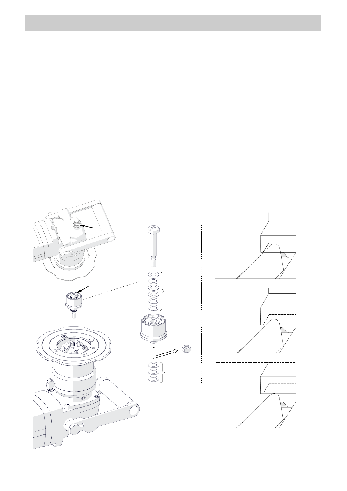
1 2 4
5
CORRECT
INCORRECT
INCORRECT
Washers
Distance
3
3.7. Replacing the roller
Unplug the machine from the power source, and place the machine upside down.
Next, press the spindle lock button (1, Fig. 8), and then use the 5 mm hex wrench to
unscrew the roller (2).
Remove
and then place the
the nut (3) and assemble the rol ler wi th t he pivot pin by usi ng w ashers ( 4),
roller on the milling head, press and hold the button (1), and tighten
the roller with the 5 mm hex wrench (2). Use such a number of washers to keep a little
gap between the roller and the cutting inserts (5). The number of 0.5-mm and 0.1-mm
washers needed depends on the milling head used. Place all unused washers between
the pivot pin and the roll er .
(collision
between
roller and
cutting insert)
unused
✓
washers
(too large gap
between roller
and cutting
insert)
14
Fig. 8. Replacing the roller
Page 15
STARTUP AND OPERATION
BM-16
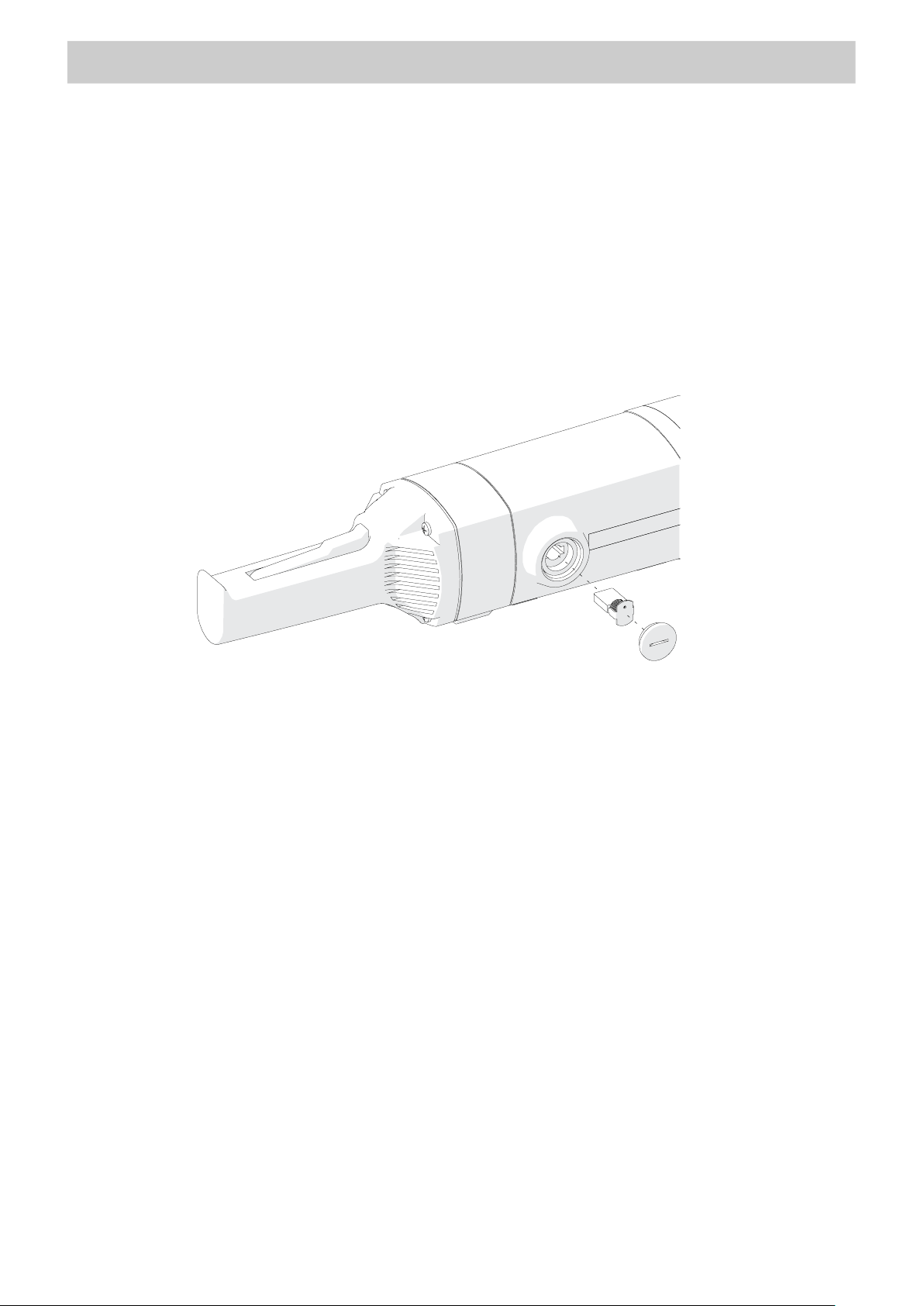
3.8. Replacing the brushes
Check the condition of the carbon brushes every 200 work hours. To do this, unplug
the machine from the power source, unscrew the cap, and remove the brush (Fig. 9).
If the length of the brush is less than 10 mm (0.4’’), replace both brushes with new
ones. To install brushes, proceed in reverse order. After the replacement, run the
motor without load for 20 minutes.
Fig. 9. Replacing the brushes
15
Page 16
BM-16
Part number:
ACCESSORIES
4. ACCESSORIES
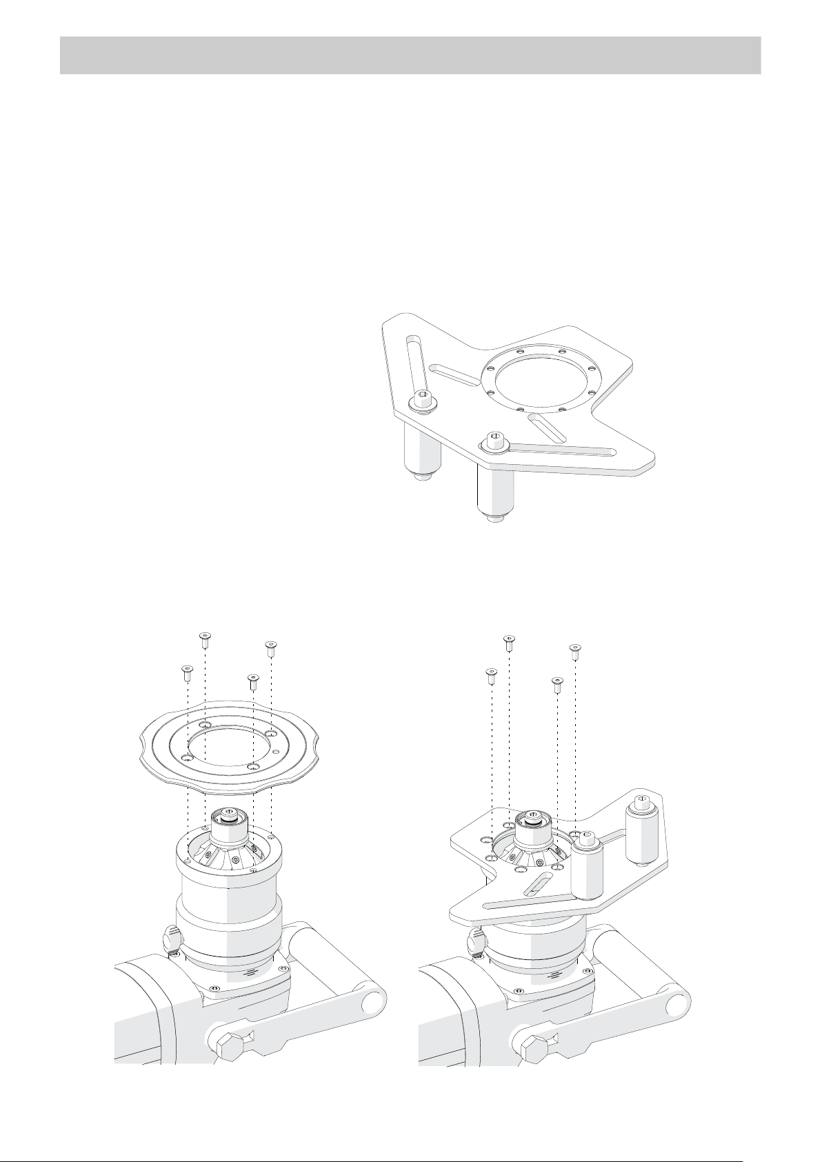
4.1. Guide for bevelling pipes
Allows external bevelling of pipes with a diameter of at least 150 mm (5.9’’) and internal
bevelling of pipes with a diameter of at least 110 mm (4.3’’).
WAP-BM16/1130
PRW-0509-07-00-00-0
(includes: four M5x12 screws,
torx screwdriver, 6 mm hex wrench)
To install, unplug the machine from the power source, and put the machine upside
down (Fig. 10). Use heat to increase the temperature of the screws. Then, use the torx
screwdriver to unscrew the standard guide and screw in the gui de for pipes .
16
Fig. 10. Installing the guide for pipes
Page 17
BM-16
2
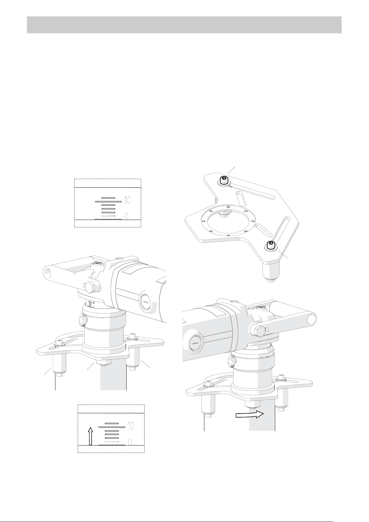
2 1 3 4 4 6 5
ACCESSORIES
Rotate the sleeve to set ‘0’ on the pitch (1, Fig. 11), and then use the 6 mm hex
wrench to loosen the guide rollers (2) and separate them from each other as far as
possible. Place the machine on a vertically positioned pipe, pressing the roller (3)
to the pipe, and then move the rollers (4) evenly to join them to the pipe and tighten
in this position. Next, separate the machine from the pipe, and set the required
parameters (5). Then, start the machine, slowly slide it toward the edge, and bevel
according to the direction 6.
Fig. 11. Using the machine on a pipe
17
Page 18
BM-16
Part number:
Part number:
ACCESSORIES
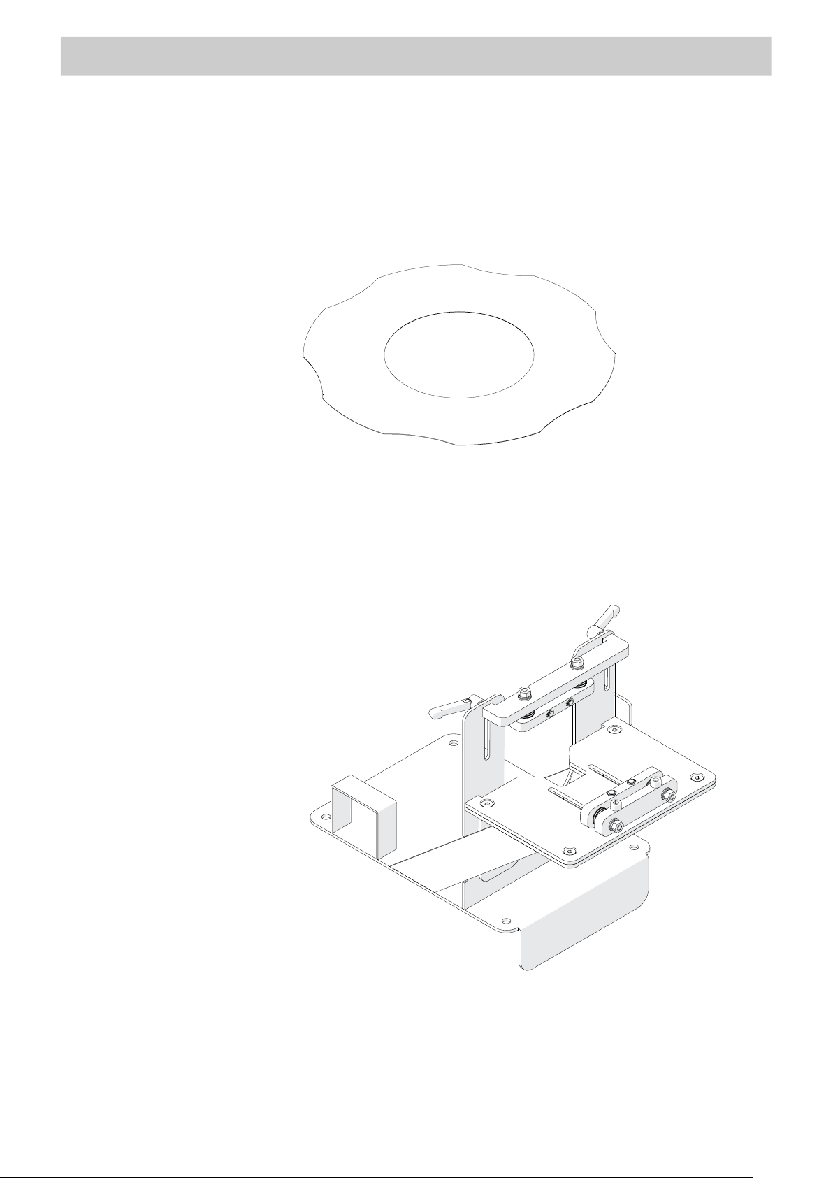
4.2. Anti-scratch guide sticker
Self-adhesive guide sticker against scratches is dedicated for aluminum bevelling.
If the sticker is removed, clean excess glue from the guide with petroleum ether.
NKL-0509-05-00-00-0
WAP-BM16/1140
4.3. Worktable fixture
Designed to bevel workpieces with cross section of at least 15×25 mm (0.6×1’’) and
length of at least 400 mm (16’’). The width of the workpiece can be up to 100 mm (4’’),
and height up to 65 mm (2.5’’). The maximum bevel width is 14 mm (0.55’’).
WAP-BM16/1135
ZBD-0509-12-00-00-0
(includes 5 mm hex wrench)
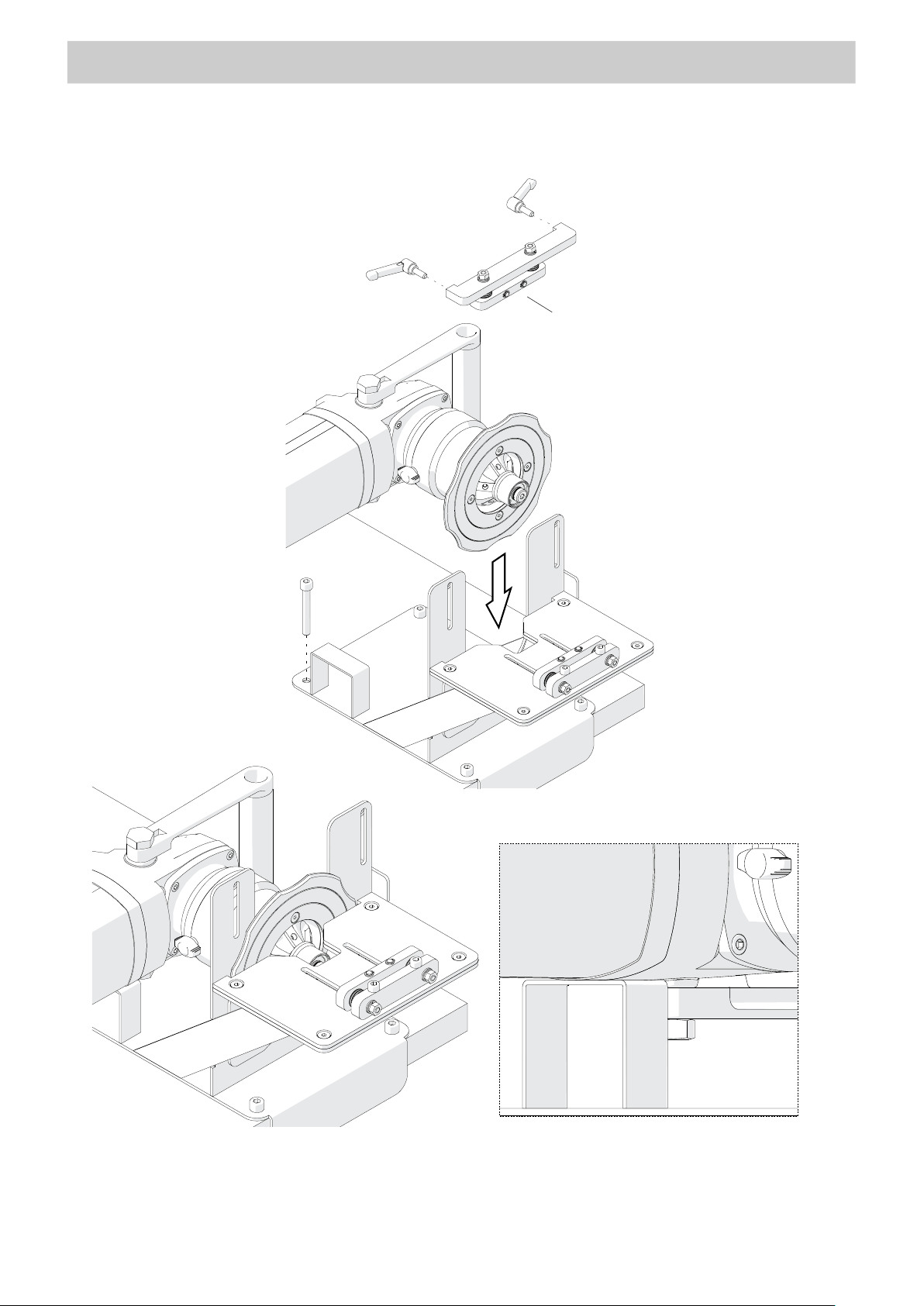
Install the worktable fixture by using holes in the base (1, Fig. 12). Then, unscrew the
18
levers and remove the vertical clamp (2). Unplug the machine from the power source,
and rotate the sleeve to set ‘0’ on the pitch. Next, place the machine with a bevelling
milling head into the worktable fixture (3) so that the motor rests on the suppor t (4).
Page 19
BM-16
2 1 3
4
ACCESSORIES
Fig. 12. Installing the machine into the worktable fixture
19
Page 20
BM-16
3 1 2
4
5
ACCESSORIES
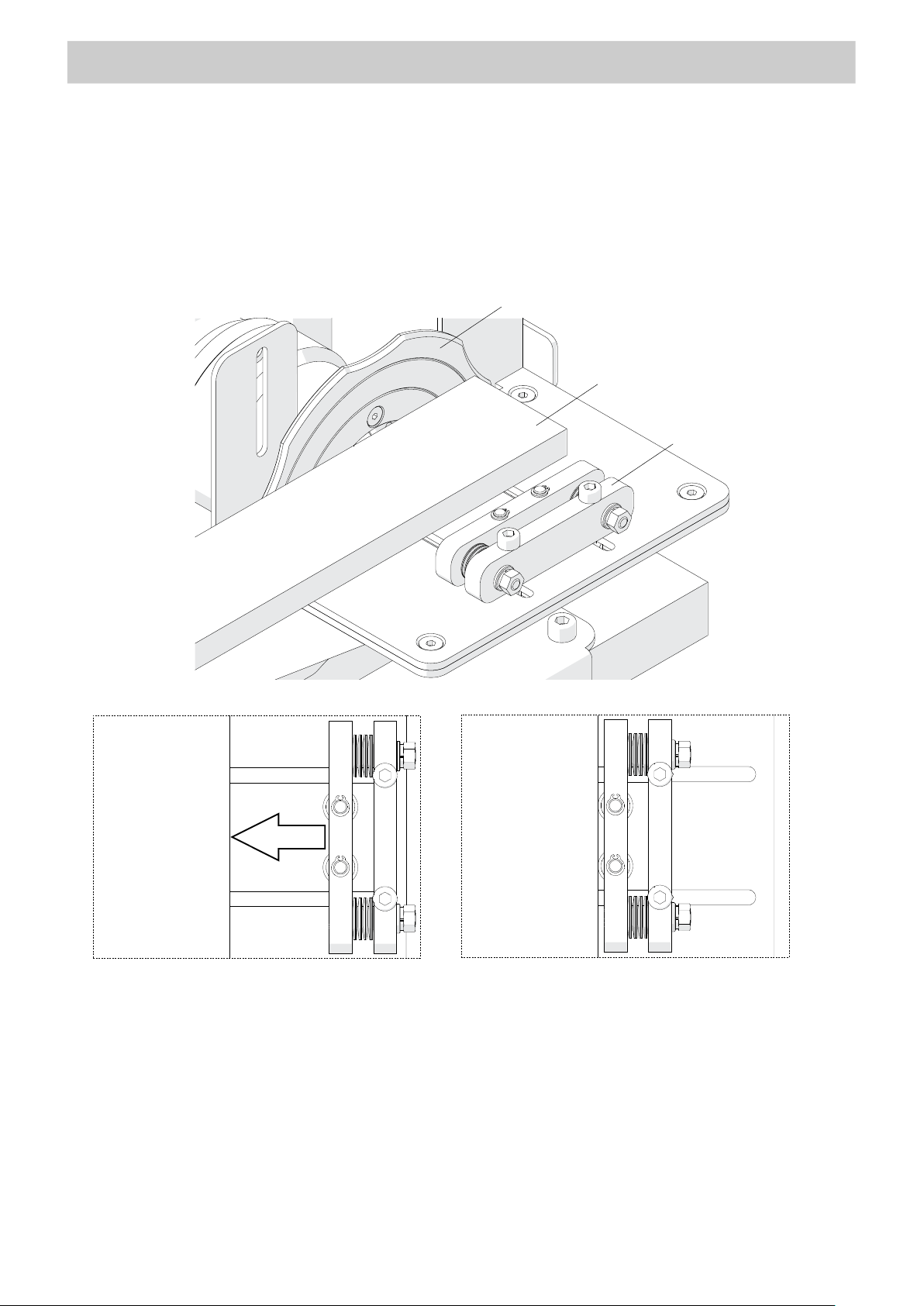
Use the 5 mm hex wrench to loosen the horizontal clamp (1, Fig. 13), and then
place the workpiece (2) s o that it makes contact with the guide (3). Next, move the
horizontal clamp toward the workpiece (4) and tighten the screws in this position (5).
Fig. 13. Adjusting the horizontal clamp
20
Page 21
BM-16
3
2 1 5 6 4
ACCESSORIES
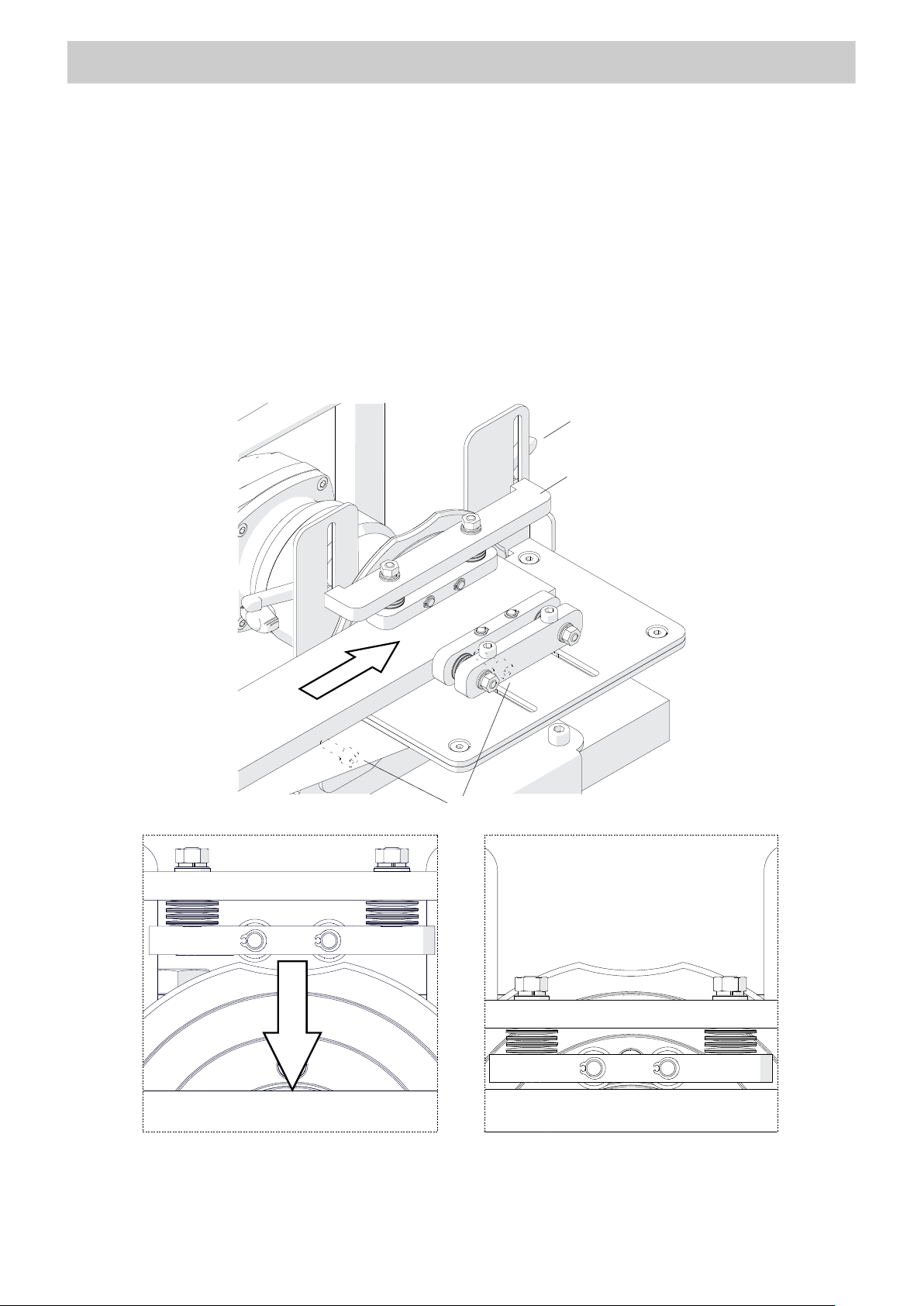
Install the vertical clamp (1, Fig. 14) by lightly tightening the levers (2), move the
clamp
to the workpiece (3), and then tighten the levers in this pos it ion (4). Next, remove
the workpiece, set the required bevel parameters, and then use the 5 mm hex wrench
to tighten the screws (5) to fix the machine.
Start the machine and set the required rotational speed. Then, place the workpiece
on the left and bevel according to the direction 6.
Fig. 14. Adjusting the vertical clamp
21
Page 22
BM-16
Part number:
R2
R3
R4
R5
2
4 1 3
ACCESSORIES
4.4. Radius insert positioner
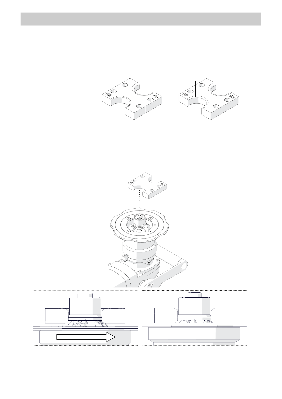
Allows the guide to be set properly for bevelling with a radius of 2, 3, 4, or 5 mm.
UST-0509-16-00-00-0
WAP-BM16/1085
Unplug the machine from the power source, place the machine upside down, and
then lower the sleeve to access the cutting inserts. Next, place the positioner from the
top (1, Fig. 15) so that the edge marked with a given radius is alig ned wit h the edg es of
three cutting inserts with the same radius
(2). Finally, rotate the sleeve (3) so that the
guide makes contact with the positioner (4).
Fig. 15. Adjusting the guide for bevelling with radius
22
Page 23
BM-16
SPARE AND WEARING PARTS
BM-16
4.5. Milling tools
Part Number Description
WAP-BM16/1035 Bevelling milling head 22.5°
WAP-BM16/1010 Bevelling milling head 30°
WAP-BM16/1030 Bevelling milling head 37.5°
WAP-BM16/1015 Bevelling milling head 45°
WAP-BM16/1017 Bevelling milling head 50°
WAP-BM16/1025 Bevelling milling head 55°
WAP-BM16/1020 Bevelling milling head 60°
WAP-BM16/1022 Bevelling milling head 65°
WAP-BM16/1070 Bevelling insert for steel (5 required)
WAP-BM16/1065 Bevelling insert for aluminum (5 required)
WAP-BM16/1100 Fixing screw for bevelling insert
WAP-BM16/1040 Radius milling head
WAP-BM16/1045 Radius insert R2 (4 required)
WAP-BM16/1050 Radius insert R3 (4 required)
WAP-BM16/1055 Radius insert R4 (4 required)
WAP-BM16/1060 Radius insert R5 (4 required)
WAP-BM16/1090 Fixing screw for radius insert
5. SPARE AND WEARING PARTS
Part Number Description
SCZ-000031 Carbon brush for 110 V
WAP-BM16/1105 Carbon brush for 230 V
WAP-BM16/1110 Grease for screws (5 g, 0.17 oz)
23
Page 24
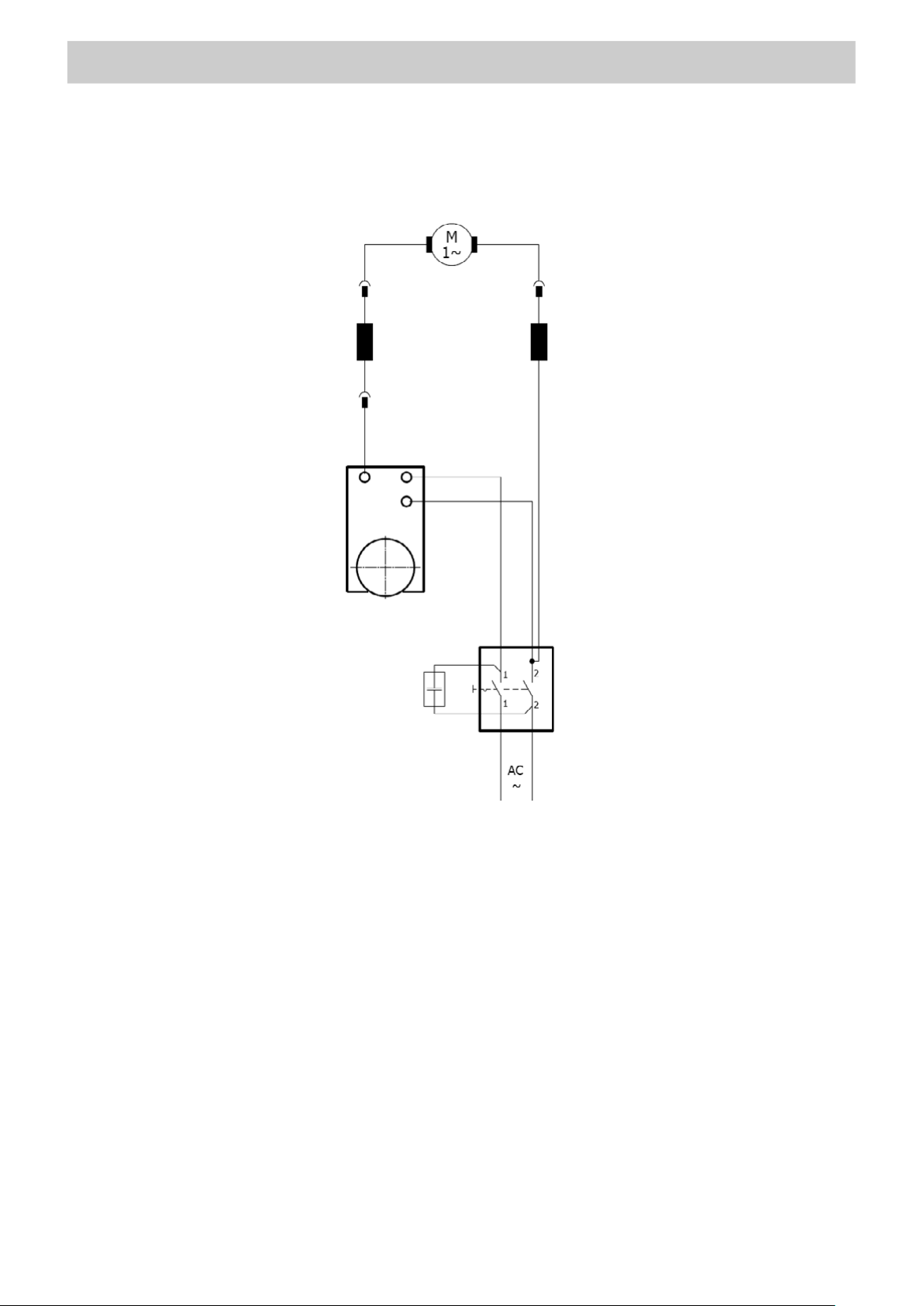
BM-16
6. WIRING DIAGRAM
WIRING DIAGRAM
24
Page 25
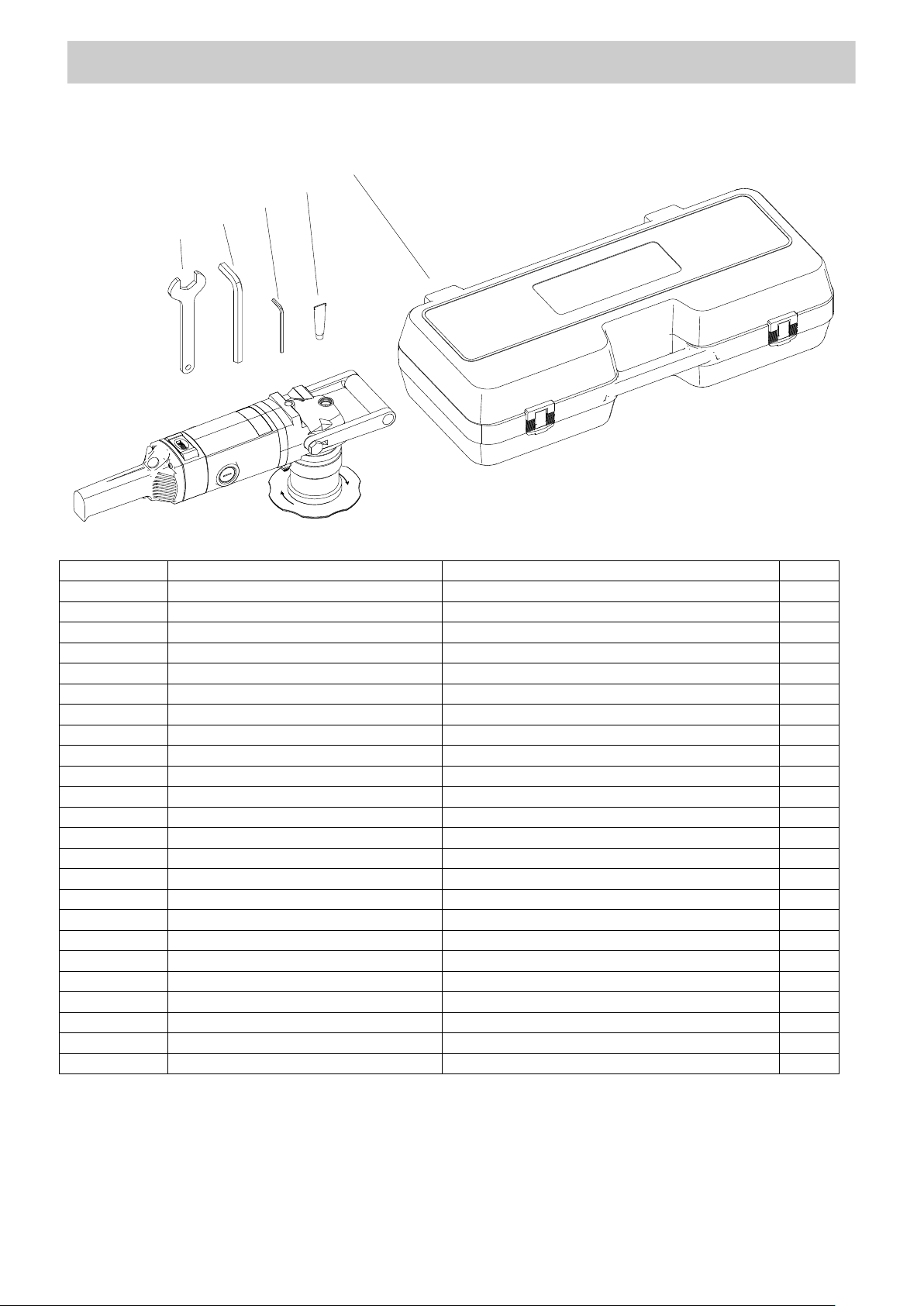
Parts list BM-16 v.1.10
ITEM
PART NUMBER
DESCRIPTION
Q-TY
1
-
32 MM SPECIAL FLAT WRENCH
1
2
-
14 MM HEX WRENCH
1
3
-
5 MM HEX WRENCH
1
4
WAP-BM16/1110
GREASE FOR SCREWS
1
5
-
PLASTIC BOX
1
–
WAP-BM16/1010
MILLING HEAD 30°
1
–
WAP-BM16/1015
MILLING HEAD 45°
1
–
WAP-BM16/1020
MILLING HEAD 60°
1
–
WAP-BM16/1025
MILLING HEAD 55°
1
–
WAP-BM16/1030
MILLING HEAD 37.5°
1
–
WAP-BM16/1035
MILLING HEAD 22.5°
1
–
-
MILLING HEAD 20°
1
–
WAP-BM16/1017
MILLING HEAD 50°
1
–
WAP-BM16/1065
MILLING HEAD 65°
1
–
-
MILLING HEAD 27.5°
1
–
-
MILLING HEAD 40°
1
–
WAP-BM16/1070
BEVELING INSERT FOR STEEL
5
–
WAP-BM16/1065
BEVELING INSERT FOR ALUMINIUM
5
–
WAP-BM16/1100
MOUNTING SCREW FOR BEVELING INSERT
5
–
WAP-BM16/1040
RADIUS MILLING HEAD
1
–
WAP-BM16/1050
RADIUS INSERT R3
4
–
WAP-BM16/1055
RADIUS INSERT R4
4
–
WAP-BM16/1060
RADIUS INSERT R5
4
–
WAP-BM16/1090
MOUNTING SCREW FOR RADIUS INSERT
4
PARTS LIST
5
4
3
2
1
– optional
25
Page 26

Parts list BM-16 v.1.10
PARTS LIST
12
21
11
9
10
23
16
24
8
7
3
17
22
15
13
6
2
19
20
5
33
1
27
32
31
18
26
30
28
32
31
25
29
4
26
Page 27

Parts list BM-16 v.1.10
ITEM PART NUMBER DESCRIPTION Q-TY
1
TLJ-0427-01-03-00-1
SLIDING SLEE VE
1
2
PRW-0427-01-05-00-0
GUIDE
1
3
TLJ-0509-01-01-00-1
SPINDLE SLEEVE
1
4
RLK-0509-04-00-00-0
GUIDING ROLLER ASSY
1 5 WRZ-0509-01-02-00-0
SPINDLE
1 6 TLJ-0509-01-03-00-0
DISTANCE SLEEVE
1
7
KOL-0509-01-04-00-0
BEVEL GEAR z=5 3
1
8
NKR-0509-01-05-00-0
LOCKING NUT
1
9
PRS-000342
BEARING COVER 35x55x2.5
1
10
PDK-000187
DISTANCE WASHER 0.2
1
11
PDK-000188
DISTANCE WASHER 0.3
1
12
NPD-000012
MOTOR ASSY 230V (CEE)
1
13
PRS-000019
EXTERNAL RETAINING RING 28z
1
15
PRS-000285
SEAL A-RING 28x42x7
1
16
PRS-000286
SEAL O-RING 80x3
1
17
PRS-000274
SEAL O-RING 72x3
1
18
PKT-000037
HANDLEVER
1
19
WKR-000539
TORX COUNTERSUNK HEAD SCREW M5x12
4
20
WPS-000010
KEY 5x5x14
1
21
LOZ-000174
BALL BEARING 30x55x13
1
22
SRB-000086
HEX SOCKET HEAD CAP SCREW M5x20
4
23
PRS-000021
EXTERNAL RETAINING RING 30z
1
24
PRS-000343
INTERNAL RETAINING RING 55w
1
25
RLK-0427-14-02-00-1
ROLLER
1
26
SWR-0509-04-01-00-1
ROLLER PIVOT PIN
1
27
TLJ-0509-04-02-00-0
ROLLER SLEEVE
1
28
NKR-000018
HEX NUT M6
1
29
PRS-000003
EXTERNAL RETAINING RING 12z
1
30
PRS-000018
INTERNAL RETAINING RING 28w
1
31
PDK-000174
WASHER 8x14x0.1
3
32
PDK-000010
WASHER 8x14x0.5
4
33
LOZ-000038
BALL BEARING 12x28x8
2
PARTS LIST
27
Page 28
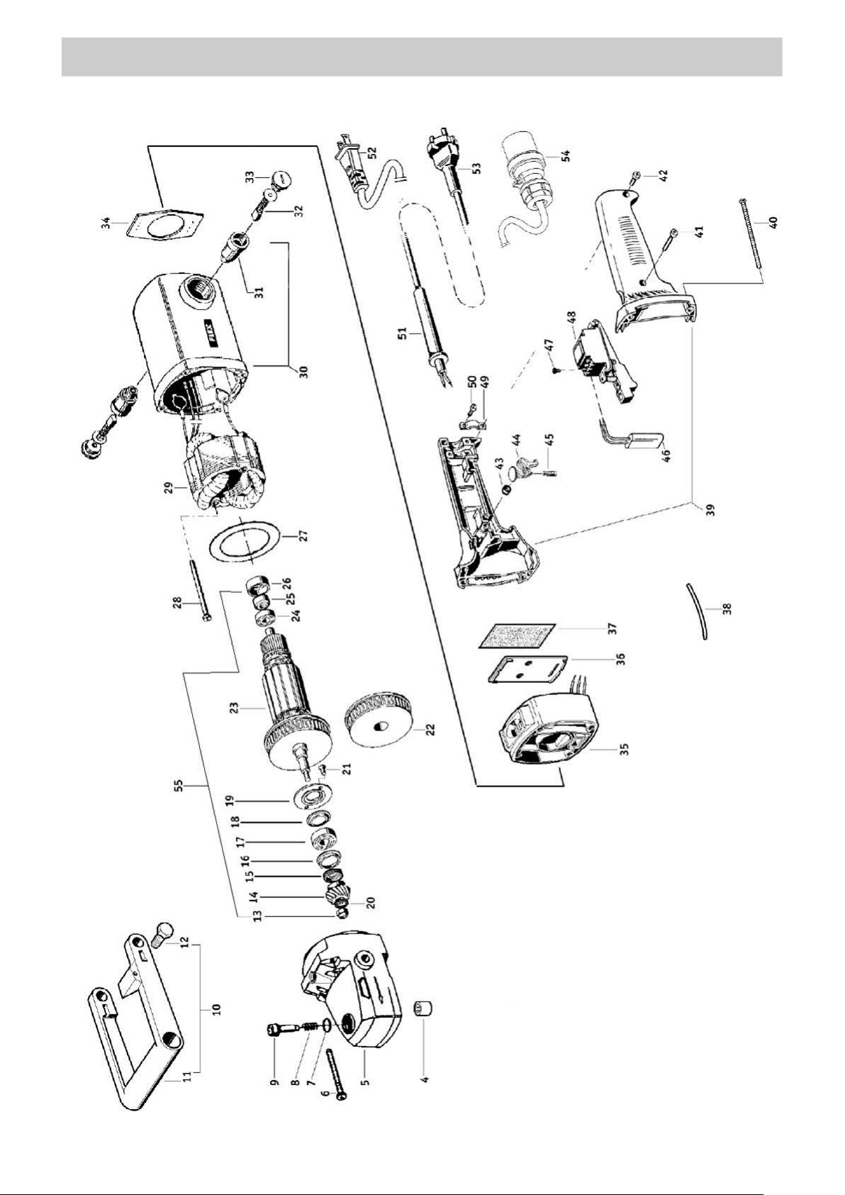
Parts list BM-16 v.1.10
PARTS LIST
28
Page 29

PARTS LIST
Parts list BM-16 v.1.10
4
LOZ-000133
SLIDE SLEEVE HK 151 2
1
5
KRP-000070
GEAR BODY
1 6 SRB-000338
HEAD SCREW TX25 M5x45
4 7 PRS-000291
SEALING RING 18W
1
8
SPR-000050
SPRING
1
9
SWR-000002
SPINDLE LOCK PIVOT PIN
1
10
RKJ-000059
FRONT HANDLE ASSY
1
11
RKJ-000060
FRONT HANDLE
1
12
SRB-000341
FULLY THREADED HEX CAP SCREW M14x25
2
13
NKR-000145
NUT M8x1
1
14
KOL-000089
BEVEL GEAR MZ 1.5x12
1
15
DYS-000009
DISTANCE
1
16
USZ-000044
SEALING
1
17
LOZ-000135
BALL BEARING 15x35x11
1
18
USZ-000045
SEALING 6003JV
1
19
PKR-000051
COVER
1
20
PDK-000189
WASHER NL8
1
21
WKR-000433
HEX SOCKET COUNTERSUNK HEAD SCREW M5x16
2
22
WNT-000009
FAN 1 23
WRN-000045
ROTOR 230V
1
24
LOZ-000136
BALL BEARING 12x28x8
1
25
PRS-000292
MAGNETIC RING
1
26
LOZ-000137
BEARING
1
27
OSL-000187
STATOR GUARD 230/CEE
1
28
SRB-000343
SCREW KT-KT 5x74
2
29
STN-000032
STATOR 230V
1
30
OBD-000035
STATOR HOUSING 230V
1
31
SCT-000010
BRUSH HOLDER 230V
2
32
SCZ-000030
BRUSH 230V
2
33
PKR-000046
BRUSH HOLDER COVER
2
34
PKR-000047
HANDLE COVER SB
1
35
ZSP-000014
ROTATIONAL SPEED CONTROLLER UNIT 230V
1
36
PKR-000048
CONTROLLER BODY COVER
1
37
PDK-000193
INSULATION WASHER
1
38
OSL-000189
WIRE SHIELD GF
1
39
KRP-000075
HANDLE BODY
1
40
SRB-000343
SCREW KT-KT 5x74
4
41
SRB-000344
SCREW KT-KT 4x30
1
42
SRB-000345
SCREW KT-KT 4x20
1
43
TLJ-000108
LOCK SLEEVE
1
44
BLD-000016
SWITCH LOCK
1
45
SPR-000052
SPRING
1
46
KND-000138
CAPACITOR X2 0.22uF
1
47
SRB-000348
SCREW M3.5x7 DK4.1
1
48
WLC-000035
SWITCH
1
49
WSP-000059
WIRE BRACKET PA6
1
50
SRB-000345
SCREW KT-KT 4x20
2
51
OSL-000191
WIRE SHIELD fi9
1
51
OSL-000192
WIRE SHIELD fi11
1
52
PWD-000150
POWER CORD AWG 16/2 SJ 120 (US)
1
ITEM PART NUMBER DESCRIPTION Q-TY
NPD-000012 MOTOR ASSY 230V (CEE)
29
Page 30

PARTS LIST
Parts list BM-16 v.1.10
53
PWD-000151
POWER CORD H07RN-F 2x1Qx4M
1
54
PWD-000152
POWER CORD WITH PLUG BS 4343
1
55
WRN-000058
ROTOR ASSY – 230V
1
NPD-000012 MOTOR ASSY 230V (CEE)
ITEM PART NUMBER DESCRIPTION Q-TY
30
 Loading...