

Page 1
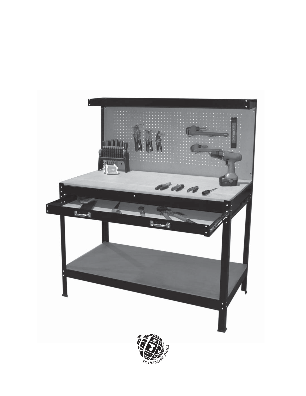
WORK TABLE & BACK BOARD
ASSEMBLY INSTRUCTIONS
21 Staffern Drive
Concord, ON L4K 2X2
www.trademarktools.ca
Page 2
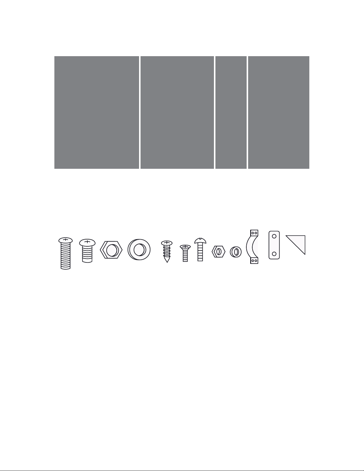
CONTENTS OF THE WORK TABLE & BACKBOARD CARTON
ABCD
A. Bottom board (1198 x 598 x 6 mm)
B. Table-top board (1198 x 598 x 15 mm)
C. Holed back board (1200 x 217 x 6 mm)
D. Peg board (1188 x 607 x 4.5 mm)
123 4 56789101112
1. Bolt M6 x 15 mm (8pcs)
2. Bolt M6 x 10 mm (63pcs)
3. Nut M6 (71pcs)
4. Washer M6 (71pcs)
5. Wood Screw (4pcs)
6. Bolt M x 10 mm (8pcs) (for handle)
7. Bolt M4 x 12 mm (10pcs)
8. Nut (18pcs)
9. Washer M4 x 14 mm (18pcs)
10. Drawer Handle (2pcs)
11. Reinforced metal plate (1pc)
12. Feet plastic protector (4pcs)
Page 3
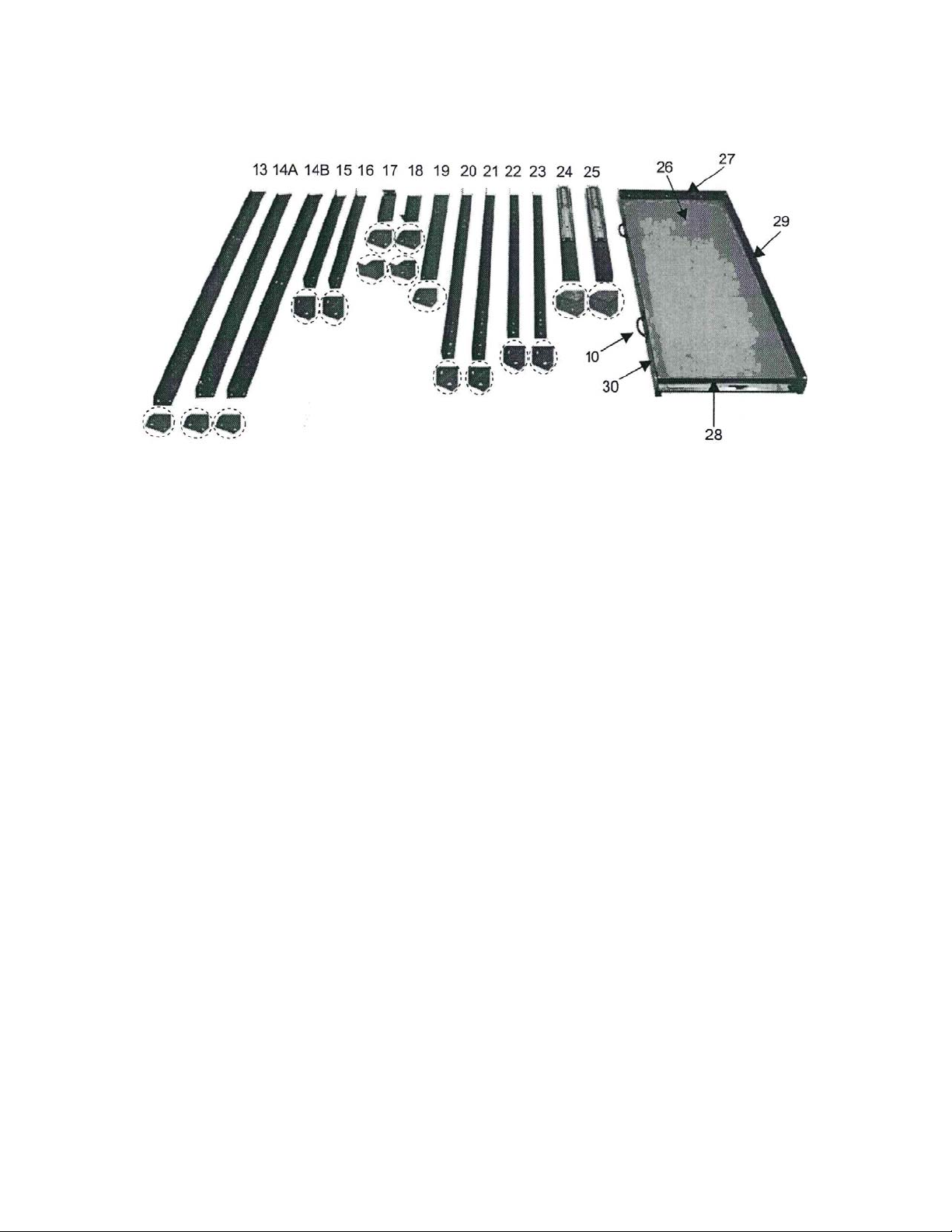
CONTENTS OF THE WORK TABLE & BACKBOARD CARTON (cont.)
13. Top rail 1198 mm (2pcs)
14A. Cross member 1186 mm (3pcs)
14B. Cross member (with holes in centre) 1186 mm (2pcs)
15. Left holed back board support 640 mm (1pc)
16. Right holed back board support 640 mm (1pc)
17. Left top cantilever arm 215 mm (1pc)
18. Right top cantilever arm 215 mm (1pc)
19. Side rail 586 mm (4pcs)
20. Left rear leg 996 mm (1pc)
21. Right rear leg 996 mm (1pc)
22. Left front leg 900 mm (1pc)
23. Right front leg 900 mm (1pc)
24. Left guide rail 599.4 mm (1pc) (for mounting drawer)
25. Right guide rail 599.4 mm (1pc) (for mounting drawer)
26. Drawer bottom (1pc) (drawer size 1093 x 448 mm)
27. Drawer left side panel (1pc)
28. Drawer right side panel (1pc)
29. Drawer rear panel (1pc)
30. Drawer front panel (1pc)
Page 4
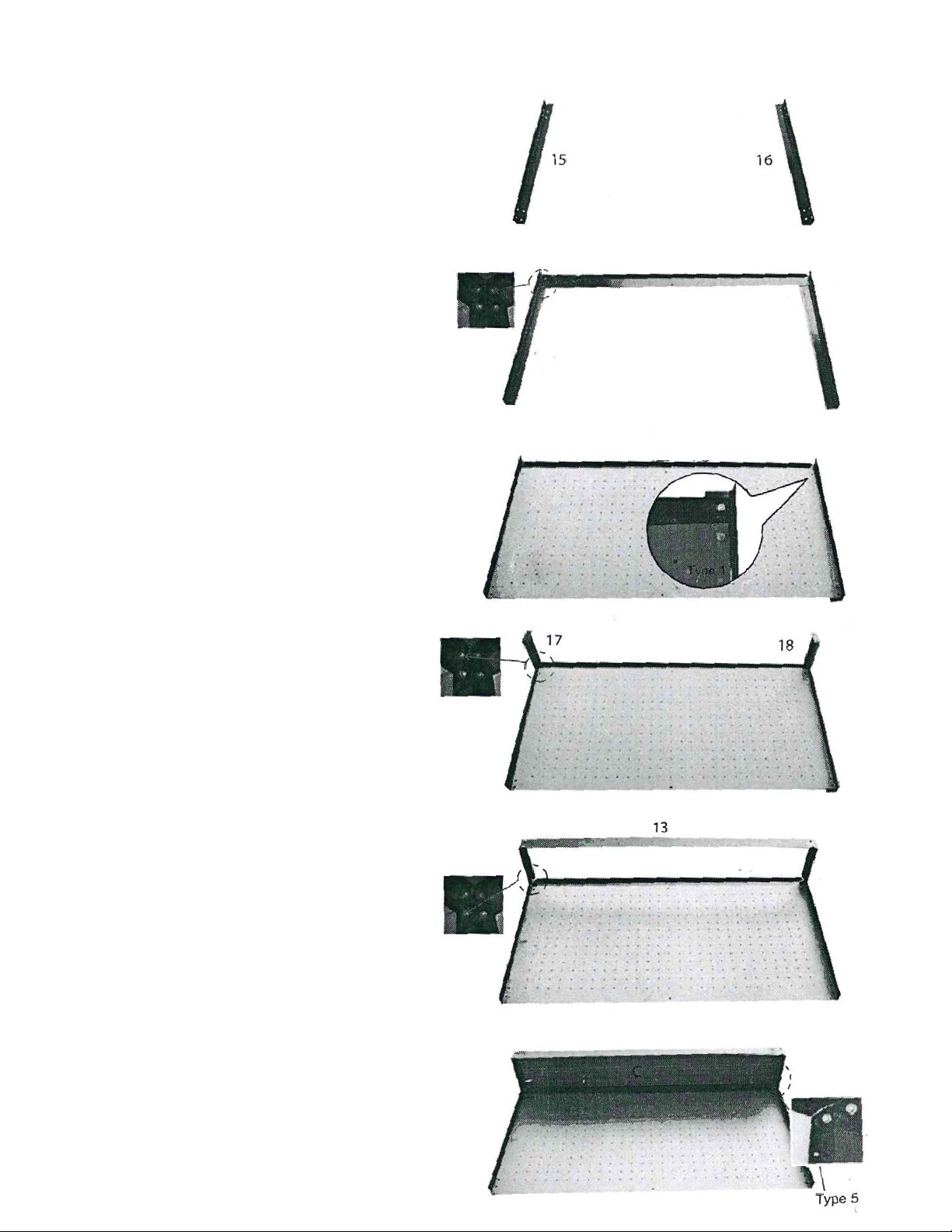
TOOL BOARD ASSEMBLY
STEP 1
Place the left holed back board support (15)
and the right holed back board support (16)
on a level surface.
STEP 2
Mount a cross member (13) between
the holed back board supports. Fasten the
corners using bolts, washers and nuts provided.
STEP 3
Place the holed back board (D) in between
14B
14B
the frames (as shown).
Use two M6 x 15 mm bolts (type 1),
washers and nuts at the top to fasten the
holed back board (D) to the frame.
STEP 4
Position the left top cantilever arm (17)
and the right top cantilever arm (18)
in the corners of the frame.
STEP 5
Mount the top rail (13) between the
two top cantilever arms. Fasten the
corners of the frame using the bolts,
washers and nuts as shown.
STEP 6
Mount the top board (C) on top of the
frame using the wood screws (type 5).
Page 5
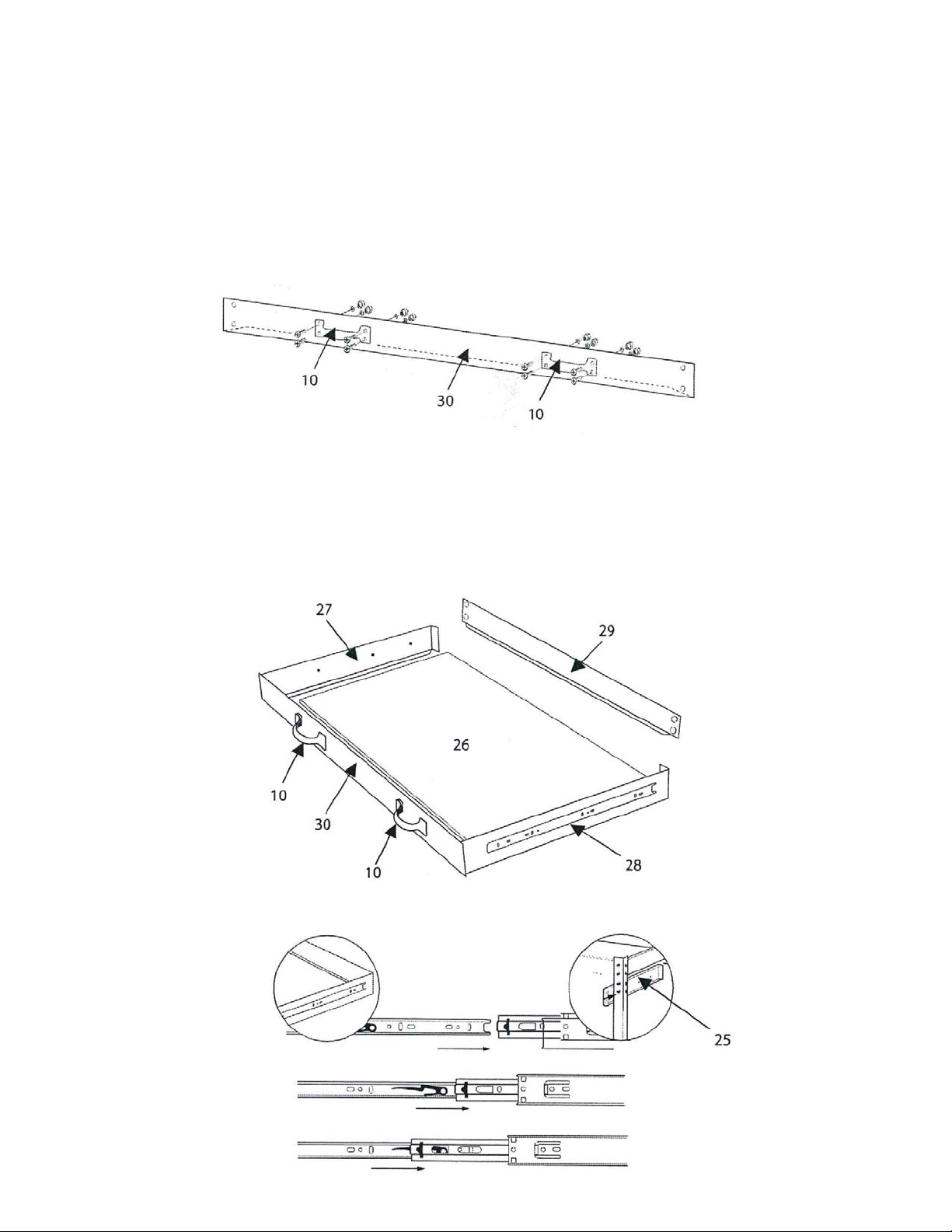
DRAWER ASSEMBLY
STEP 1
Attach the drawer handles (10) to the drawer front panel (30) using the bolts,
washers and nuts (type 7).
STEP 2
Assemble the drawer unit as shown below, and use bolts and nuts to fasten the corners.
Page 6
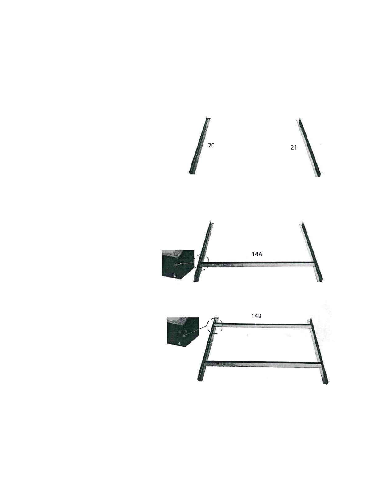
WORK STATION ASSEMBLY
STEP 1
Place left rear leg (20) and right rear leg (21)
on a level surface.
STEP 2
Connect the two rear legs, at the
bottom, with a cross member (14A).
STEP 3
Mount another cross member (14B)
at the top of the legs.
Page 7
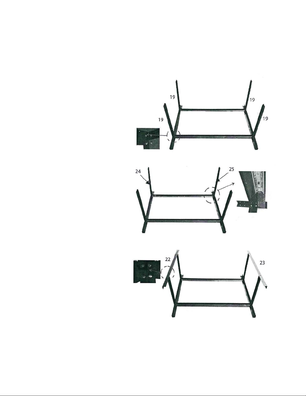
WORK STATION ASSEMBLY (cont.)
STEP 4
Place the four side rails (19)
on the rear legs.
STEP 5
Mount the left guide rail (24) and
the right guide rail (25) on the rear
legs, at the top, as shown.
STEP 6
Place the left front leg (22) and
the right front leg (23) on the
side rails.
Page 8
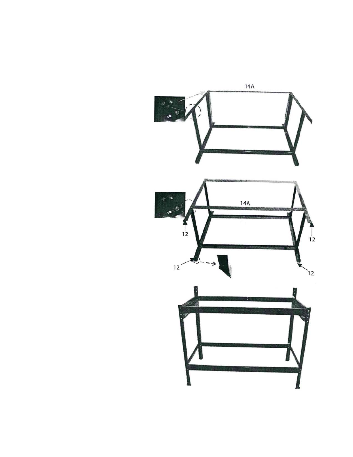
WORK STATION ASSEMBLY (cont.)
STEP 7
Mount a cross member (14A)
between the front legs (on the upper frame)
and secure with bolts and nuts.
STEP 8
Mount a second cross member (14A)
between the front legs (on the lower frame)
and secure with bolts and nuts.
Place the feet plastic protectors (12)
on the base of each foot.
STEP 9
Place the work station in the
upright position.
Page 9
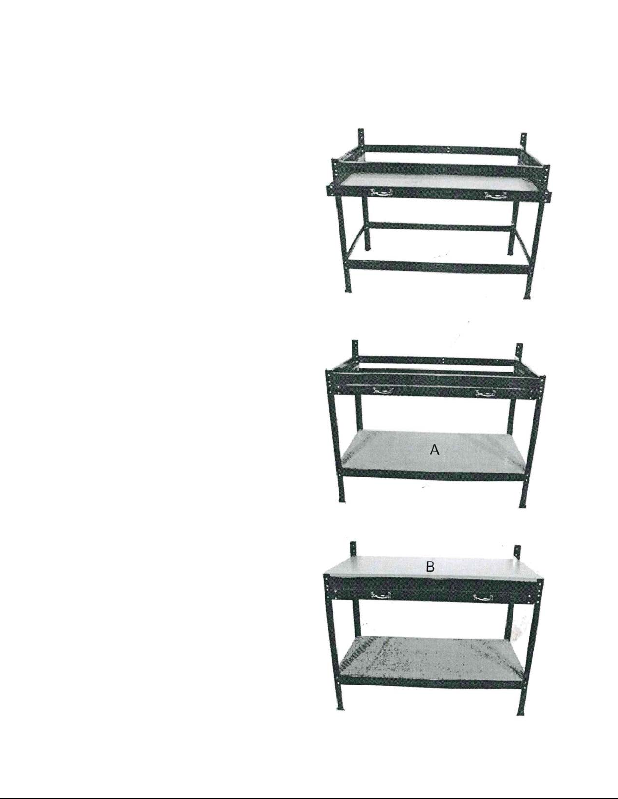
WORK STATION ASSEMBLY (cont.)
STEP 10
Slide the assembled drawer into place
along the guide rails (24) and (25).
STEP 11
Place the bottom board (A) on the lower
part of the work station (as shown).
STEP 12
Place the table top board (B) on the top
section of the work station.
Page 10
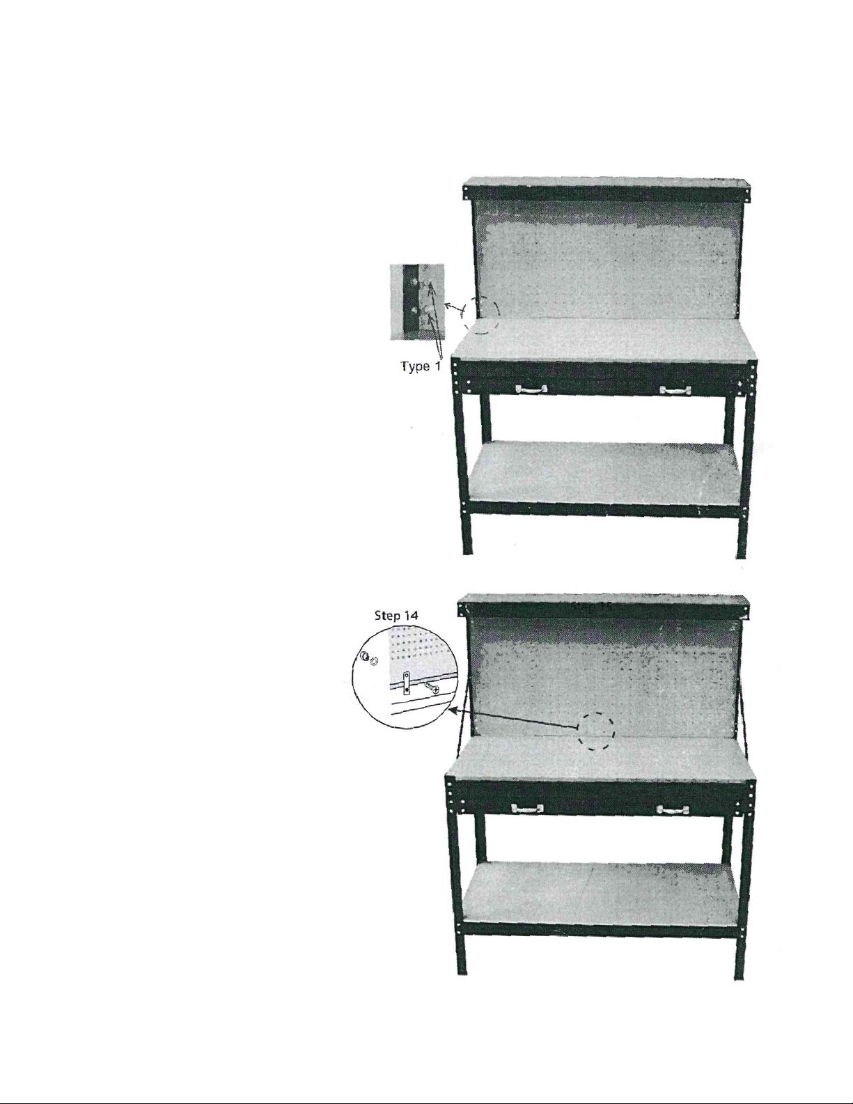
WORK STATION ASSEMBLY (cont.)
STEP 13
Mount the assembled Tool Board
on the table and securely fasten using
M6 x 15 mm bolts (type 1) through
the openings in the holed board.
STEP 14
Fix the reinforced metal plate (11) onto
the back lower part of the assembled
Table Top Board and secure tightly with
the bolts, washers and nuts provided.
 Loading...