


JBOD SSR-4N108L
User Manual

Compliance information
European Union EMC Directive conformance statement
This product is in conformity with the protection requirements of EU Council Directive
2014/30/EU on the approximation of the laws of the Member States relating to
electromagnetic compatibility. TradeDX cannot accept responsibility for any failure to satisfy
the protection requirements resulting from a non-recommended modification of the product.
This product has been tested and found to comply with the limits for Class A Information
Technology Equipment according to CISPR 32/European Standard EN 55032. The limits for
Class A equipment were derived for commercial and industrial environments to provide
reasonable protection against interference with licensed communication equipment.
Attention: This is a Class A product. In a domestic environment this product may cause radio
interference in which case the user may be required to take adequate measures.
CE Declaration of Conformity
This product has been tested in accordance to, and complies with the European Low Voltage
Directive (2014/35/EU) and European EMC Directive (2014/30/EU).
The product has been marked with the CE Mark to illustrate its compliance.
Disclaimer
The information in this document is subject to change without notice. The manufacture makes
no representations or warranties with respect to the contents hereof and specifically disclaims
any implied warranties of merchantability or fitness for any particular purpose. Furthermore, The
manufacturer reserves the right to revise this publication and to make changes from time to time
in the content hereof without obligation to notify any person of such revision or changes.
Safety Information
Read this important safety information section. Retain this manual for reference. Read this
section before servicing.
CAUTION:
To reduce the risk of electric shock, this JBOD should only be serviced by qualified service personnel.
RTC Battery
CAUTION:
Danger of explosion if battery is incorrectly replaced. Replace only with same or equivalent type recommended by
the manufacturer. Discard used batteries according to the manufacturer’s instructions.
Laser Drive Equipment
The optical transceiver module in this JBOD is a laser Class 1 product.
Ambient Operation
This equipment cannot be operated above an ambient operation temperature of 40
degrees centigrade.
Equipment Location
This equipment can only be accessed by SERVICE PERSONNEL or by USERS who have been
instructed about the reasons for the restrictions applied to the location. Access is through the
use of a TOOL or lock and key, or other means of security, and is controlled by the authority
responsible for the location.

Further Safety Information
Be sure to read all caution and danger statements in this documentation before performing
the instructions. Read any additional safety information that comes with your JBOD or
optional de- vice before you install the device.
Safety Precautions
For your protection, observe the following safety precautions when setting up your equipment:
Follow all cautions and instructions marked on the equipment.
Ensure that the voltage and frequency of your power source match the voltage and
frequency
Never push objects of any kind through openings in the equipment. Dangerous
voltages may be
Conductive foreign objects could produce a short circuit that could cause fire, electric
shock, or
inscribed on the equipment’s electrical rating label.
present.
damage to your equipment.
Safety Instructions
1. Please read these safety instructions carefully.
2. Please keep this Manual for later reference.
3. Please disconnect this equipment from AC outlet before cleaning. Don’t use liquid or sprayed
detergent for cleaning. Use moist sheet or cloth for cleaning.
4. For pluggable equipment, the socket-outlet must be installed near the equipment and must be
easily accessible.
5. Please keep this equipment from humidity.
6. Place this equipment on a safe reliable surface when installing. A drop or fall could cause injury.
7. Enclosure openings are for air circulation and protect the equipment from overheating. DO NOT
COVER THE OPENINGS.
8. Make sure the voltage of the power source matches rated voltages.
9. Place the power cord so that it won’t be stepped on or tripped over. Do not place anything on top
of the power cord.
10. All cautions and warnings on the equipment should be noted.
11. If the equipment is not used for a long time, disconnect the equipment from outlet to avoid dam-
age to the system by transient voltages.
12. Do not spill liquids onto equipment; this may cause fire or electrical shock.
13. Never open the equipment. For safety reasons, the equipment should only be opened by qualified
service personnel.
14. If any of the following situations arises, have the equipment checked by qualified service:
a) The power cord or plug is damaged.
b) Liquid seeped into the equipment.
c) The equipment has been exposed to moisture.
d) The equipment does not work well or operation does not match behavior describe in user’s
manual.
To Connect:
To Disconnect:
1. Turn everything OFF.
1. Turn everything OFF.
2. First, attach all cables to devices.
2. First, remove power cords from outlet.
3. Attach signal cables to connectors.
3. Remove signal cables from connectors.
4. Attach power cords to outlet.
4. Remove all cables from devices.
5. Turn device ON.
e) The equipment has been dropped or damaged.
f) The equipment has obvious signs of damage. DO NOT LEAVE THIS EQUIPMENT IN AN
ENVIRONMENT WHERE TEMPERATURES EX- CEED 60 °C (140 °F); IT MAY DAMAGE THE
EQUIPMENT.
Symbols
The following symbols will appear in this manual to indicate different safety precaution:
Hazardous voltages are present. To reduce the risk of electric shock and danger to
personal health, follow the instructions.
There is a risk of personal injury and equipment damage. Follow the instructions.
Hot surface. Avoid contact. Surfaces are hot and may cause personal injury if
touched.
Safety Statements
DANGER:
Electrical current from power, telephone, and communication cables is hazardous. To
avoid a shock hazard:
• Do not connect or disconnect any cables or perform installation, maintenance, or
reconfiguration of this product during an electrical storm.
• Connect all power cords to a properly wired and grounded electrical outlet.
• Connect to properly wired outlets any equipment that will be attached to this product.
• When possible, use one hand only to connect or disconnect signal cables.
• Never turn on any equipment when there is evidence of fire, water, or structural damage.
• Disconnect the attached power cords, telecommunications systems, networks, and
modems before you open the device covers, unless instructed otherwise in the installation
and configuration procedures.
• Connect and disconnect cables as described in the following table when installing, moving,
or opening covers on this product or attached devices.
CAUTION:
When replacing the lithium battery, use only Foxconn Part Number XXXXX or an equivalent type battery recommended by The manufacture. If your system has a module containing a lithium battery, replace it only with the
same module type made by the same manufacturer. The battery contains lithium and can explode if not properly
used, handled, or disposed of.
Do not:
Throw or immerse into water
Heat to more than 100°C (212°F)
Repair or disassemble
Dispose of the battery as required by local ordinances or regulations.
CAUTION:
When laser products (such as CD-ROMs, DVD drives, fiber optic devices, or transmitters) are installed, note the
following:
Do not remove the covers. Removing the covers of the laser product could result in exposure to
hazardous laser radiation. There are no serviceable parts inside the device.
Use of controls or adjustments or performance of procedures other than those specified herein might
result in hazardous radiation exposure.
DANGER:
Some laser products contain an embedded Class 3A or Class 3B laser diode. Note the following.
Laser radiation when open. Do not stare into the beam, do not view directly with optical instruments, and avoid
direct exposure to the beam.
DANGER:
Class 1 Laser
CAUTION:
The following label indicates sharp edges, corners, or joints nearby.
CAUTION:
The following label indicates a hot surface.
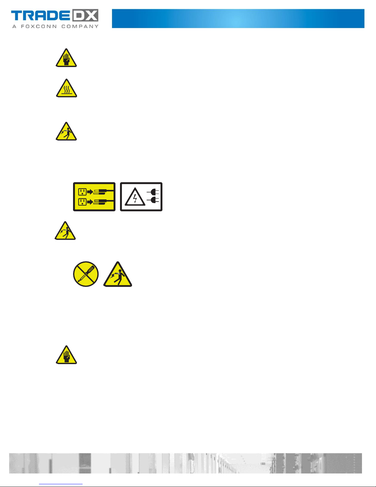
CAUTION:
The power control button on the device and the power switch on the power supply do not turn off the electrical
current supplied to the device. The device also might have more than one power cord. To remove all electrical
current from the device, ensure that all power cords are disconnected from the power source.
CAUTION:
Never remove the cover on a power supply or any part that has the following label attached.
Hazardous voltage, current, and energy levels are present inside any component that has this label attached.
There are no serviceable parts inside these components. If you suspect a problem with one of these parts, contact
a service technician.
Attention: This JBOD is suitable for use on an IT power distribution system whose maximum phase-to- phase
voltage is 240 V under any distribution fault condition.
DANGER:
Overloading a branch circuit is potentially a fire hazard and a shock hazard under certain conditions. To avoid these
hazards, ensure that your system electrical requirements do not exceed branch circuit protection require- ments.
Refer to the information that is provided with your device for electrical specifications.
CAUTION:
Do not place any object on top of rack-mounted devices.
Attention: This JBOD is suitable for use on an IT power distribution system whose maximum phase-to-phase voltage
is 240 V under any distribution fault condition.
CAUTION:
Hazardous moving parts are nearby.

Table of Contents
Introduction ................................................................................................................................................ 13
Checklist .................................................................................................................................................. 13
System Tour ............................................................................................................................................ 13
Front View ............................................................................................................................................... 14
Rear View ................................................................................................................................................ 15
Rear Panel Board ................................................................................................................................. 15
System Architecture ................................................................................................................................ 16
System Operations ...................................................................................................................................... 17
Powering on ............................................................................................................................................ 17
Powering down ....................................................................................................................................... 17
Set Storage Configuration ....................................................................................................................... 17
Set steps with BMC IPMI command .................................................................................................... 17
Get JBOD Topology Configuration ...................................................................................................... 19
Hardware Installation ................................................................................................................................. 21
Introduction ............................................................................................................................................ 21
Safety Measures .................................................................................................................................. 21
Power supply Units (PSU) ....................................................................................................................... 22
Removing a Power Supply Unit ........................................................................................................... 22
Installing a Power Supply Unit ............................................................................................................ 22
System Fans ............................................................................................................................................ 23
Removing a System Fan ...................................................................................................................... 23
Installing a System Fan ........................................................................................................................ 23
HDD Drawer ............................................................................................................................................ 24
Opening a HDD Drawer ....................................................................................................................... 24
Closing a HDD Drawer ......................................................................................................................... 24
Removing a HDD Drawer .................................................................................................................... 25
Installing a HDD Drawer ...................................................................................................................... 26
Removing a HDD Drawer in limited space .......................................................................................... 28
Installing a HDD Drawer in limited space ............................................................................................ 31
Top Cover ................................................................................................................................................ 33
Removing a Rear Top Cover ................................................................................................................ 33

Installing a Rear Top Cover ................................................................................................................. 34
Removing a Front Top Cover............................................................................................................... 35
Installing a Front Top Cover ................................................................................................................ 36
Storage .................................................................................................................................................... 37
Installing a 3.5'' HDD ........................................................................................................................... 37
Removing a 3.5'' HDD .......................................................................................................................... 39
Expander Board ....................................................................................................................................... 40
Removing an Expander Board ............................................................................................................. 40
Installing an Expander Board .............................................................................................................. 41
Cable Cover ............................................................................................................................................. 42
Removing a Cable Cover ..................................................................................................................... 42
Installing a Cable Cover ....................................................................................................................... 42
Cable Chain Module ................................................................................................................................ 43
Removing a Cable Chain Module ........................................................................................................ 43
Installing a Cable Chain Module .......................................................................................................... 43
Rear Panel Board (RPB) ........................................................................................................................... 44
Removing Rear Panel Board ................................................................................................................ 44
Installing Rear Panel Board ................................................................................................................. 45
Fan Board ................................................................................................................................................ 45
Removing a Fan Board ........................................................................................................................ 45
Installing a Fan Board .......................................................................................................................... 46
Power Distribution Board Cover (PDB Cover) ......................................................................................... 47
Removing a Power Distribution Board Cover ..................................................................................... 47
Installing a Power Distribution Board Cover ....................................................................................... 47
Power Distribution Board (PDB) ............................................................................................................. 48
Removing a Power Distribution Board ................................................................................................ 48
Installing a Power Distribution Board ................................................................................................. 48
Chassis Management Module (CMM) .................................................................................................... 49
Removing a Chassis Management Module ......................................................................................... 49
Installing a Chassis Management Module .......................................................................................... 49
Inner Rail ................................................................................................................................................. 50
Removing an Inner Rail ....................................................................................................................... 50

Installing an Inner Rail ......................................................................................................................... 51
Rail Bracket ............................................................................................................................................. 52
Removing a Rail Bracket ...................................................................................................................... 52
Installing a Rail Bracket ....................................................................................................................... 53
HDD Backplane ........................................................................................................................................ 54
Removing a HDD Backplane ................................................................................................................ 54
Installing a HDD Backplane ................................................................................................................. 55
Connectors .................................................................................................................................................. 57
Expander Boards ..................................................................................................................................... 57
Fan Board ................................................................................................................................................ 57
Power Distribution Board ....................................................................................................................... 58
HDD Backplane 1 ..................................................................................................................................... 58
HDD Backplane 2 ..................................................................................................................................... 59
Rear Panel Board (RPB) ........................................................................................................................... 59
Chassis Managemnt Module (CMM) ...................................................................................................... 60
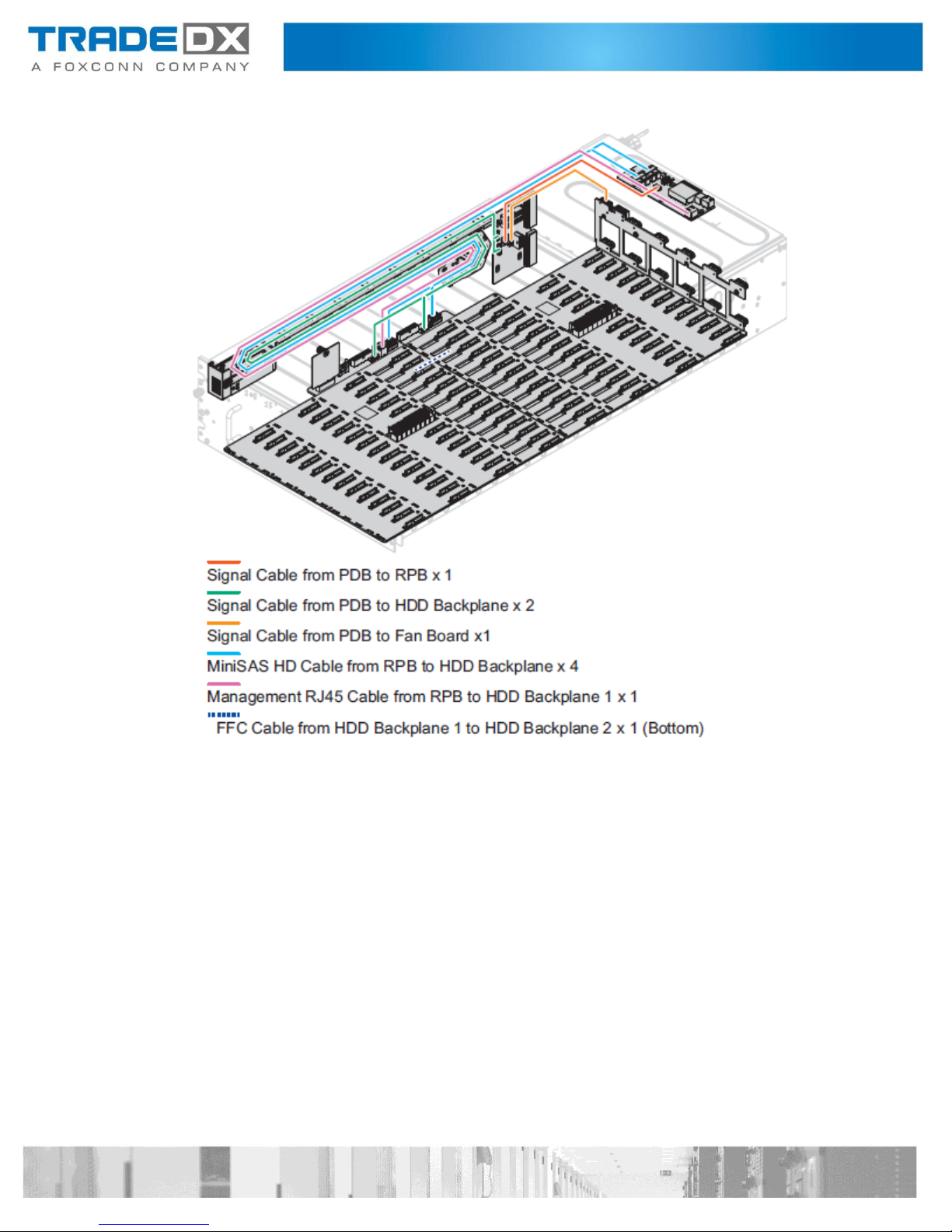
Cabling......................................................................................................................................................... 60
Power Cable Routing ............................................................................................................................... 60
Signal Cable Routing ............................................................................................................................... 61
Rackmount Installation ............................................................................................................................... 62
Removing a Chssis from the Rack ........................................................................................................... 62
Installing a Chassis on the Rack............................................................................................................... 63
Removing the Rackmount Rails .............................................................................................................. 64
Installing the Rackmount Rails ................................................................................................................ 65
Configuration .............................................................................................................................................. 68
Chassis Management Module (CMM) .................................................................................................... 68
IP Address............................................................................................................................................ 68
Username and Password .................................................................................................................... 68
Updating the CMM Firmware ............................................................................................................. 68
Checking the CMM FW Version Using Linux ........................................................................................... 73
Checking the System Event Log Using Linux ........................................................................................... 73
List All Sensors and Status Using Linux ................................................................................................... 74
Storage Drive LEDs .................................................................................................................................. 74

Updating Expander Board Firmware....................................................................................................... 74
Updating Expander Board Firmware Using Linux ................................................................................... 75
Checking Expander Version Using Linux ................................................................................................. 80
Specification ................................................................................................................................................ 84
Before You Contact TradeDX ...................................................................................................................... 84
Contact ........................................................................................................................................................ 85
Introduction
The SSR-4N108L features 4U JBOD with 108 HDD trays.
Checklist
Carefully unpack the SSR-4N108L box and check that the following items were included.
SSR-4N108L
2 x External miniSAS HD cable
2 x Power cord (optional)
2 x L brackets
Contact your vendor if some items are missing or appear damaged.
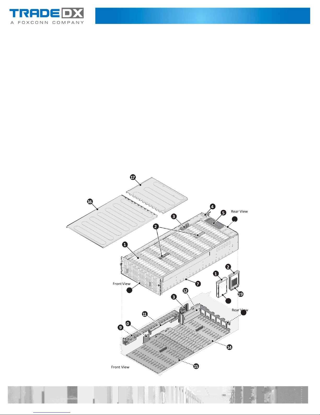
System Tour

No
Item
No
Item
1
HDD carrier x 108
2
Expander board carrier x 2
3
Power distribution board (PDB) 4
4
1600W power supply unit x 2
5
Rear panel board
6
Fan module x 12
7
4U JBOD chassis
8
HDD drawer
9
Cable chain
10
Chassis Management Module (CMM)
11
Cable cover
12
PDB cover
13
Fan board
14
HDD backplane 2
15
HDD backplane 1
16
Front top cover
17
Rear top cover
18
3.5” HDD x 108
19
Expander board x 4
No
Item
No
Item
1
HDD Drawer
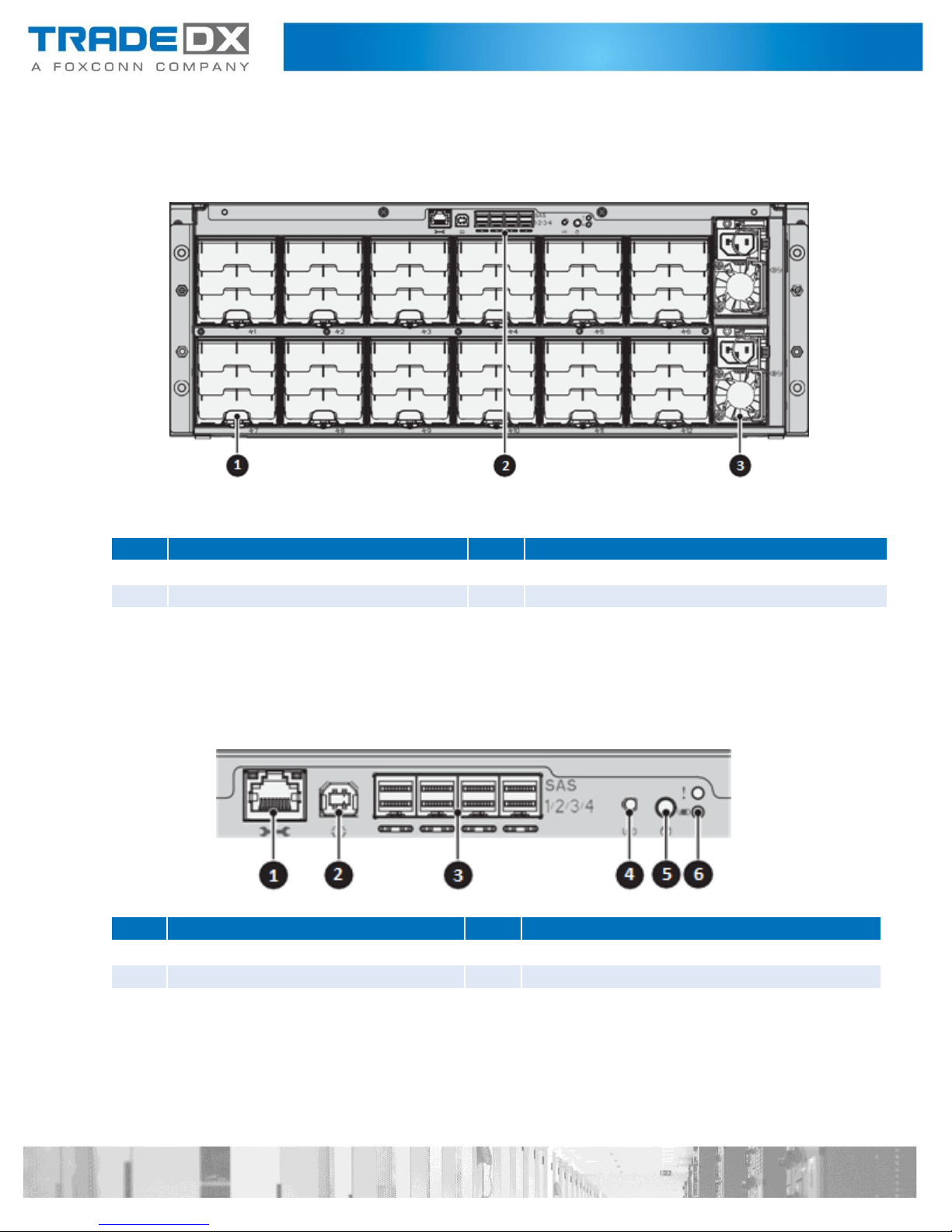
Front View
No
Item
No
Item
1
Fan Module x 12
2
Rear Panel Board
3
1600W Power Supply x 2
No
Item
No
Item
1
External management RJ45 x 1
2
Debug connector (USB type B)
3
External miniSAS HD connector x 4
5
UID button
5
Power button with LED
6
UID and system status LED
Rear View
Rear Panel Board

System Architecture

System Operations
This section provides information about getting your JBOD up and running
Powering on
Follow these steps to turn on the system:
1. Connect the power cord to the power socket at the rear of the JBOD and plug
the other end into a power outlet.
2. Press the power button once to turn on the JBOD.
Powering down
Follow these steps to power down the system:
1. Press and hold the power button to turn off the JBOD.
2. Disconnect the power cord from the power socket.
Set Storage Configuration
Prior to shipping, the system configuration is setup according to customer
requirements. The system does not require further configuration prior to powering
on.
Set steps with BMC IPMI command
Before starting this procedure, make sure the JBOD is powered on.
1. Log into Linux.
2. Open the terminal.
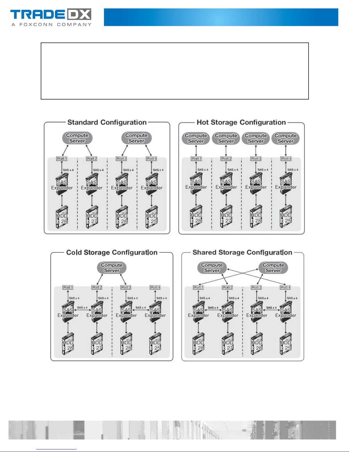
3. Execute the ipmitool command to select specified Topology mode on all installed
expanders (1~4).
Command:
#ipmitool –H <ip address> -U <username> -P <password> -I lanplus raw 0x30 0x04
<Expander ID> 0xa0 <Mode Selection>
Hint:
<Expander ID>: ID of specified expander, must be 1 ~ 4.
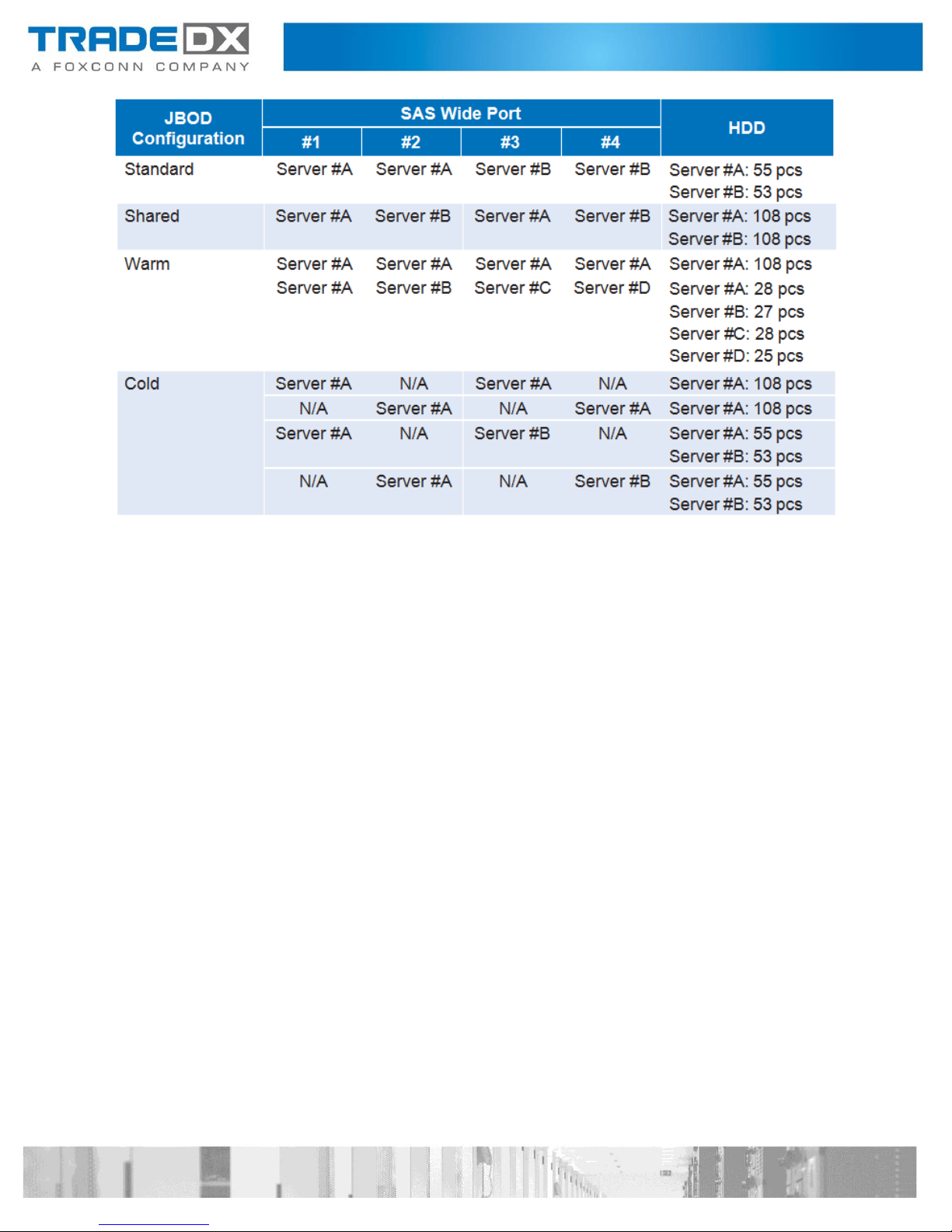
<Mode Selection>: 0x01: Standard / 0x02: Warm / 0x03: Cold / 0x04: Shared
Note:
All installed expanders must be assigned the same mode.
#ipmitool –H 192.168.0.100 -U admin -P admin -I lanplus raw 0x30 0x04 0x01 0xa0
0x01
01
#ipmitool –H 192.168.0.100 -U admin -P admin -I lanplus raw 0x30 0x04 0x02 0xa0
0x01
02
#ipmitool –H 192.168.0.100 -U admin -P admin -I lanplus raw 0x30 0x04 0x03 0xa0
0x01
03
#ipmitool –H 192.168.0.100 -U admin -P admin -I lanplus raw 0x30 0x04 0x04 0xa0
0x01
04
#ipmitool –H 192.168.0.100 -U admin -P admin -I lanplus raw 0x30 0x02 0x01 0x00
01
4. Execute the ipmitool command to reset all installed expanders after topology mode
changed.
Command:
#ipmitool –H <ip address> -U <username> -P <password> -I lanplus raw 0x30 0x02
<Expander ID> 0x00
Hint:
<Expander ID>: ID of specified expander, must be 1 ~ 4.
Example :
a. Set JBOD topology mode as “0x01: Standard”.
#ipmitool
–H
192.168.0.100
-U
admin
-P
admin
-I
lanplus
raw
0x30
0x03
0x01
01 a0 01
#ipmitool
–H 192.168.0.100
-U admin
-P admin
-I lanplus
raw
0x30
0x03
0x02
02 a0 01
#ipmitool
–H 192.168.0.100
-U admin
-P admin
-I lanplus
raw
0x30
0x03
0x03
03 a0 01
#ipmitool
–H 192.168.0.100
-U admin
-P admin
-I lanplus
raw
0x30
0x03
0x04
04 a0 01
#ipmitool –H 192.168.0.100 -U admin -P admin -I lanplus raw 0x30 0x04 0x01 0xa0
0x04
01
#ipmitool –H 192.168.0.100 -U admin -P admin -I lanplus raw 0x30 0x04 0x02 0xa0
0x04
02
#ipmitool –H 192.168.0.100 -U admin -P admin -I lanplus raw 0x30 0x04 0x03 0xa0
0x04
03
#ipmitool –H 192.168.0.100 -U admin -P admin -I lanplus raw 0x30 0x04 0x04 0xa0
0x04
04
#ipmitool –H 192.168.0.100 -U admin -P admin -I lanplus raw 0x30 0x02 0x01 0x00
01
#ipmitool –H 192.168.0.100 -U admin -P admin -I lanplus raw 0x30 0x02 0x02 0x00
02
#ipmitool –H 192.168.0.100 -U admin -P admin -I lanplus raw 0x30 0x02 0x03 0x00
03
b. Set JBOD topology mode as “0x04: Shared”.
Get JBOD Topology Configuration
Before starting this procedure, make sure the JBOD is powered on.
1. Log into the Linux.
2. Open the terminal.
3. Execute the ipmitool command to get Topology mode from installed expanders (1~4).
Command:
#ipmitool –H <ip address> -U <username> -P <password> -I lanplus raw 0x30 0x03
<Expander ID>
Hint:
<Expander ID> : ID of specified expander, must be 1 ~ 4.
Example:
a. JBOD topology mode is “0x01: Standard” currently.
#ipmitool
–H
192.168.0.100
-U
admin
-P
admin
-I
lanplus
raw
0x30
0x03
0x01
01 a0 04
#ipmitool
–H 192.168.0.100
-U admin
-P admin
-I lanplus
raw
0x30
0x03
0x02
02 a0 04
#ipmitool
–H 192.168.0.100
-U admin
-P admin
-I lanplus
raw
0x30
0x03
0x03
03 a0 04
#ipmitool
–H 192.168.0.100
-U admin
-P admin
-I lanplus
raw
0x30
0x03
0x04
04 a0 04
b. JBOD topology mode is “0x04: Shared” currently.
Hardware Installation
Introduction
The procedures in this section apply to the SSR-4N108L JBOD model
Safety Measures
Computer components and electronic circuit boards can be damaged by discharges
of static electricity. Working on computers that are still connected to a power supply
can be extremely dangerous. Follow the simple guidelines below to avoid damage to
your computer or injury to yourself.
Always disconnect the computer from the power outlet whenever you are
working inside the
If possible, wear a grounded wrist strap when you are working inside the computer
case. Alternatively, discharge any static electricity by touching the bare metal
chassis of the computer case, or the bare metal body of any other grounded
appliance.
Hold electronic circuit boards by the edges only. Do not touch the components on the
board un
Leave all components inside the static-proof packaging until you are ready to use
the component
less it is necessary to do so. Do not flex or stress the circuit board.
computer case.
for the installation.
Power supply Units (PSU)
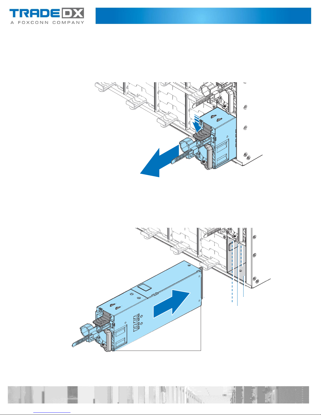
Removing a Power Supply Unit
Follow these steps to remove the power supply unit:
1. Hold a PSU handle and press the release latch to unlock from the chassis.
2. Pull a PSU out of the chassis.
Installing a Power Supply Unit
Follow these steps to install the power supply unit:
1. Align a PSU with the chassis bay.
2. Slide a PSU into the chassis and push until it is flush with the bay.
System Fans
Removing a System Fan
Follow these steps to remove a system fan:
1. Press the latch to release a fan module.
2. Slide to remove a fan module.
3. Repeat the previous steps for the remaining fans.
Installing a System Fan
Follow these steps to install a system fan:
1. Align a fan module with chassis bay.
2. Slide a fan module into the chassis and push until it is flush with the bay.
3. Repeat the previous steps for the remaining fans.
HDD Drawer
Opening a HDD Drawer
Follow these steps to open an HDD drawer:
1. Remove the screws securing an HDD drawer and the chassis.
Note:
The screws are only for shipping.
2. Loosen the thumb screws securing an HDD drawer.
3. Slide an HDD drawer out of the chassis.
Closing a HDD Drawer
Follow these steps to close an HDD drawer:
1. Slide an HDD drawer in place.
2. Secure an HDD drawer with thumb screws.
3. Secure an HDD drawer to the chassis with screws.
Removing a HDD Drawer
Follow these steps to remove an HDD drawer:
1. Power off the JBOD and detach all of the power cords from the power supply.
2. Open an HDD drawer. See “Opening an HDD Drawer” on page 13.
3. Remove a cable cover. See “Removing a Cable Cover” on page 35.
4. Remove the HDDs. See “Removing a 3.5” HDD” on page 30.
5. Remove the expander boards. See “Removing an Expander Board” on page 31.
6. Disconnect the cables from the HDD backplanes.
7. Remove the screws securing a rear cable chain bracket to the HDD drawer.
8. Slide a rear cable chain bracket to unlock and remove
9. Press the release latches to unlock the HDD drawer.
10. Pull out the HDD drawer from the chassis.
Installing a HDD Drawer
Follow these steps to install an HDD drawer:
1. Install a cable chain. See “Installing a Cable Chain Module” on page 38.
2. Pull out the middle rail and make sure ball bearing retainer is locked.
3. Align an HDD drawer with the middle rails.

4. Connect the cables to the HDD backplanes.
5. Align the rear cable chain bracket with the HDD drawer.
6. Slide a rear cable chain bracket to lock on the HDD drawer. Make sure a rear
cable chain bracket is locked on the HDD drawer.
7. Secure a rear cable chain bracket to the HDD drawer with a screw.
8. Install the expander boards. See “Installing an Expander Board” on page 33.
9. Install the HDDs. See “Installing a 3.5” HDD” on page 28.
10. Install a cable cover. See “Installing a Cable Cover” on page 36.
11. Press the release latches and slide until the HDD drawer has been inserted into the
chassis.
12. Close an HDD drawer. See “Closing an HDD Drawer” on page 14.
Removing a HDD Drawer in limited space
1. Follow these steps to remove an HDD drawer in limited space:
1. Power off the JBOD and detach all of the power cords from the power supply.
2. Open an HDD drawer. See “Opening an HDD Drawer” on page 13.
3. Remove a cable cover. See “Removing a Cable Cover” on page 35.
4. Remove the HDDs. See “Removing a 3.5” HDD” on page 30.
5. Remove the expander boards. See “Removing an Expander Board” on page 31.
6. Disconnect the cables from the HDD backplanes.
7. Remove the screws securing a rear cable chain bracket to the HDD drawer.
8. Slide a rear cable chain bracket to unlock and remove.
9. Slide an HDD drawer until it is fully extended.
10. Push the mechanism at the front of inner rail to ON.

11. Press the release latches to unlock an HDD drawer and slide an HDD drawer into the
chassis.
Slide an HDD drawer into the chassis until a click sound.

12. Pull out an HDD drawer to luck position and press the release latches to unlock.
13. Pull out an HDD drawer.

Installing a HDD Drawer in limited space
Follow these steps to install an HDD drawer in limited space:
1. Make sure the ball bearing retainer is fixed at the front of middle rail.
2. Align an HDD drawer with the middle rails.
1
2
2
3. Connect the cables to the HDD backplanes.
4. Align the rear cable chain bracket with the HDD drawer.
5. Slide a rear cable chain bracket to lock on the HDD drawer. Make sure a rear
cable chain bracket is locked on the HDD drawer.
6. Secure a rear cable chain bracket to the HDD drawer with a screw.
7. Install the expander boards. See “Installing an Expander Board” on page 33.
8. Install the HDDs. See “Installing a 3.5” HDD” on page 28.
9. Install a cable cover. See “Installing a Cable Cover” on page 36.

10. Slide in an HDD drawer until it is locked.
11. Push the mechanism at the front of inner rail to OFF.
12. Press the release latches and slide until the HDD drawer has been inserted into the
chassis.

Top Cover
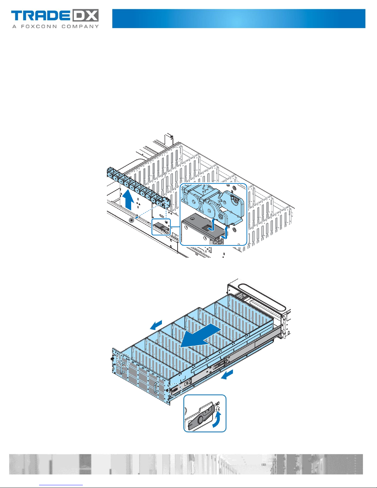
Removing a Rear Top Cover
Follow these steps to remove a rear top cover:
1. Open an HDD drawer. See “Opening an HDD Drawer” on page 13.
2. Remove a cable cover. See “Removing a Cable Cover” on page 35.
3. Remove an HDD drawer. See “Removing an HDD Drawer” on page 15.
4. Remove the screws securing the rear top cover to the chassis.
5. Flip the latch to release the rear top cover and slide the rear top cover away as
seen in the following illustration.

Installing a Rear Top Cover
Follow these steps to install a rear top cover:
1. Install a cable chain. See “Installing a Cable Chain Module” on page 38.
2. Install a front top cover. See “Installing a Front Top Cover” on page 27.
3. Align the tabs on a rear top cover with the slots on the front top cover.
4. Slide a rear top cover as shown in the following illustration.
5. Make sure a rear top cover is flush with the rear of the chassis, and secure with screws.
6. Install a cable cover. See “Installing a Cable Cover” on page 36.
7. Close an HDD drawer. See “Closing an HDD Drawer” on page 14.

Removing a Front Top Cover
Follow these steps to remove a front top cover:
1. Power off the JBOD and detach all of the power cords from the power supply.
2. Open an HDD drawer. See “Opening an HDD Drawer” on page 13.
3. Remove a cable cover. See “Removing a Cable Cover” on page 35.
4. Remove an HDD drawer. See “Removing an HDD Drawer” on page 15.
5. Remove a rear top cover. See “Removing a Rear Top Cover” on page 24.
6. Remove the screws securing a front top cover to the chassis and the cable chain.
7. Press a front top cover and slide the top cover away as seen in the following illustration.

Installing a Front Top Cover
Follow these steps to install a front top cover:
1. Install a cable chain. See “Installing a Cable Chain Module” on page 38.
2. Align a front top cover over the chassis.
3. Slide a front top cover as shown in the following illustration.
4. Make sure the top cover is flush with the front of the chassis, and secure with screws.
5. Install an HDD drawer. See “Installing an HDD Drawer” on page 17.
6. Install a cable cover. See “Installing a Cable Cover” on page 36.
7. Install a rear top cover. See “Installing a Rear Top Cover” on page 25.
8. Close an HDD drawer. See “Closing an HDD Drawer” on page 14.

Storage
Installing a 3.5'' HDD
Follow these steps to install a 3.5” HDD:
1. Open an HDD drawer. See “Opening an HDD Drawer” on page 13.
2. Press and slide the release button. The handle pops up.
3. Lift up the handle to open.
4. Remove an HDD assembly from the chassis.
5. Pry the latch on the HDD carrier to release the HDD dummy.
6. Remove an HDD dummy from the HDD carrier.

7. Align the marks on an HDD with the pins on the HDD carrier.
8. Close the latch to secure an HDD.
9. Align an HDD assembly with the connector on the HDD backplane.
10. Install an HDD assembly.
11. Gently press down on both ends of an HDD assembly to ensure it is seated in
the HDD backplane.
12. Push the handle closed.
13. Close an HDD drawer. See “Closing an HDD Drawer” on page 14.

Removing a 3.5'' HDD
Follow these steps to remove a 3.5” HDD:
1. Open an HDD drawer. See “Opening an HDD Drawer” on page 13.
2. Press and slide the release button. The handle pops up.
3. Lift up the handle to open.
4. Remove an HDD assermbly from the chassis.
5. Pry the latch on the HDD carrier to release the HDD.
6. Remove an HDD from the HDD carrier.

Expander Board
Removing an Expander Board
Follow these steps to remove an expander board:
1. Open an HDD drawer. See “Opening an HDD Drawer” on page 13.
2. Press and slide the release button. The handle pops up.
3. Lift up the handle to open.
4. Remove an expander board assembly from the chassis.
5. Remove the screws securing the expander board to the expander board bracket.
6. Remove an expander board.

Installing an Expander Board
Follow these steps to install an expander board:
1. Align the holes on an expander board with the standoffs on the expander board carrier.
2. Secure an expander board to the expander board carrier with screws.
3. Align an expander board assembly with the connector on the HDD backplane.
4. Install an expander board assembly.
5. Gently press down on both ends of an expander board assembly to ensure it
is seated in the HDD backplane.
6. Push the handle closed.
7. Close an HDD drawer. See “Closing an HDD Drawer” on page 14.

Cable Cover
Removing a Cable Cover
Follow these steps to remove a cable cover:
1. Power off the JBOD and detach all of the power cords from the power supply.
2. Open an HDD drawer. See “Opening an HDD Drawer” on page 13.
3. Remove the screws securing a cable cover to the HDD drawer.
4. Flip a cable cover and remove the cable cover from the HDD drawer.
Installing a Cable Cover
Follow these steps to install a cable cover:
1. Align the tabs on the cable cover with the slots on the HDD drawer.
2. Flip down the cable cover to secure.
3. Secure the cable cover to the HDD drawer with screws.
4. Close an HDD drawer. See “Closing an HDD Drawer” on page 14.

Cable Chain Module
Removing a Cable Chain Module
Follow these steps to remove a cable chain module:
1. Power off the JBOD and detach all of the power cords from the power supply.
2. Open an HDD drawer. See “Opening an HDD Drawer” on page 13.
3. Remove a cable cover. See “Removing a Cable Cover” on page 35.
4. Remove an HDD drawer. See “Removing an HDD Drawer” on page 15.
5. Remove the top covers. See “Removing a Front Top Cover” on page 26
and “Removing a Rear Top Cover” on page 24.
6. Remove a screw securing a front cable chain bracket to the chassis.
7. Slide a cable chain module to unlock and remove.
Installing a Cable Chain Module
Follow these steps to install a cable chain module:
1. Align the holes on a front cable chain bracket with the standoffs on the chassis.
2. Slide a cable chain module to lock on the chassis.
3. Secure a cable chain module to the chassis with a screw.
4. Install the top covers. See “Installing a Front Top Cover” on page 27 and
“Installing a Rear Top Cover” on page 25.
5. Install an HDD drawer. See “Installing an HDD Drawer” on page 17.
6. Install a cable cover. See “Installing a Cable Cover” on page 36.
7. Close an HDD drawer. See “Closing an HDD Drawer” on page 14.
Rear Panel Board (RPB)
Removing Rear Panel Board
Follow these steps to remove a RPB:
1. Power off the JBOD and detach all of the power cords from the power supply.
2. Open an HDD drawer. See “Opening an HDD Drawer” on page 13.
3. Remove a rear top cover. See “Removing a Rear Top Cover” on page 24.
4. Disconnect the cables from a RPB.
5. Remove the screws securing a RPB to the chassis.
6. Slide a RPB to unlock from the chassis standoffs and remove.
Installing Rear Panel Board
Follow these steps to install a RPB:
1. Align the I/O ports on a RPB with the slots on the chassis.
2. Slide a RPB into position. Make sure the I/O ports are seated correctly.
3. Lower a RPB onto the chassis. Make sure the screw holes on a RPB and chassis are
aligned.
4. Secure a RPB to the chassis with screws.
5. Connect the cables to a RPB.
6. Install a rear top cover. See “Installing a Rear Top Cover” on page 25.
7. Close an HDD drawer. See “Closing an HDD Drawer” on page 14.
Fan Board
Removing a Fan Board
Follow these steps to remove a fan board:
1. Power off the JBOD and detach all of the power cords from the power supply.
2. Open an HDD drawer. See “Opening an HDD Drawer” on page 13.
3. Remove a rear top cover. See “Removing a Rear Top Cover” on page 24.
4. Disconnect the cables from a fan board.
5. Remove the screws securing a fan board to the chassis.
6. Slide a fan board to unlock from the chassis standoffs and remove.

Installing a Fan Board
Follow these steps to install a fan board:
1. Align the holes on a fan board with the holes on the chassis.
2. Lower a fan board onto the chassis. Make sure a fan board is locked on the chassis.
3. Secure a fan board to the chassis with screws.
4. Connect the cables to a fan board.
5. Install a rear top cover. See “Installing a Rear Top Cover” on page 25.
6. Close an HDD drawer. See “Closing an HDD Drawer” on page 14.

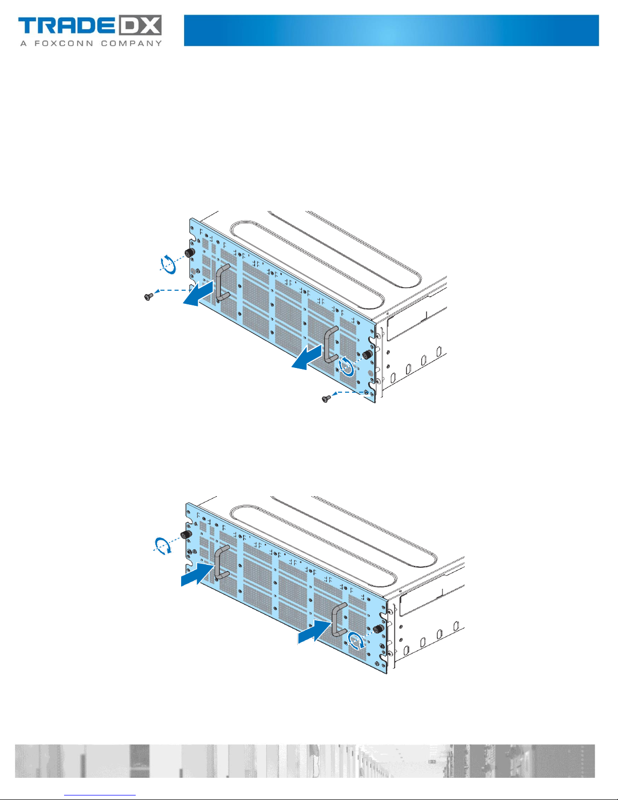
Power Distribution Board Cover (PDB Cover)
Removing a Power Distribution Board Cover
Follow these steps to remove a PDB cover:
1. Power off the JBOD and detach all of the power cords from the power supply.
2. Open an HDD drawer. See “Opening an HDD Drawer” on page 13.
3. Remove a rear top cover. See “Removing a Rear Top Cover” on page 24.
4. Remove a screw securing a PDB cover to the chassis.
5. Remove a PDB cover.
Installing a Power Distribution Board Cover
Follow these steps to install a PDB cover:
1. Align the hole on a PDB cover with the hole on the chassis. Make sure the
standoffs on the chassis are locked with the PDB cover.
2. Secure a PDB cover to the chassis with a screw.
3. Install a rear top cover. See “Installing a Rear Top Cover” on page 25.
4. Close an HDD drawer. See “Closing an HDD Drawer” on page 14.

Power Distribution Board (PDB)
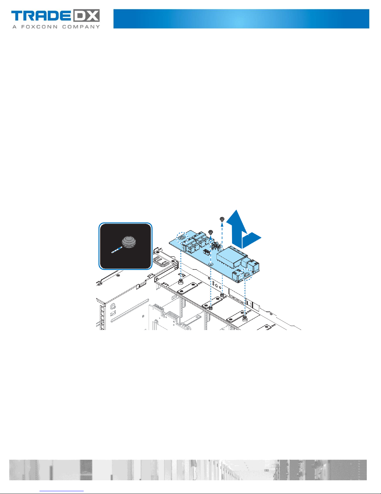
Removing a Power Distribution Board
Follow these steps to remove a PDB:
1. Power off the JBOD and detach all of the power cords from the power supply.
2. Open an HDD drawer. See “Opening an HDD Drawer” on page 13.
3. Remove a rear top cover. See “Removing a Rear Top Cover” on page 24.
4. Remove a PDB cover. See “Removing a Power Distribution Board Cover
(PDB Cover)” on page 43.
5. Disconnect the cables from a PDB.
6. Remove a screw securing a PDB to the chassis.
7. Remove a PDB.
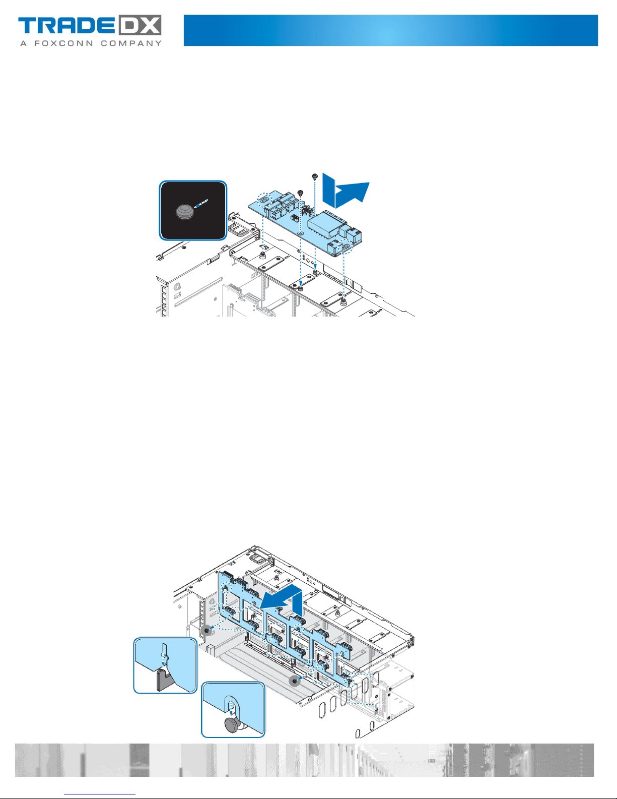
Installing a Power Distribution Board
Follow these steps to install a PDB:
1. Align the holes on the PDB with the standoffs on the chassis.
2. Slide a PDB to lock in place.
3. Secure a PDB to the chassis with a screw.

4. Connect the cables to a PDB.
5. Install a PDB cover. See “Installing a Power Distribution Board Cover
(PDB Cover)” on page 44.
6. Install a rear top cover. See “Installing a Rear Top Cover” on page 25.
7. Close an HDD drawer. See “Closing an HDD Drawer” on page 14.
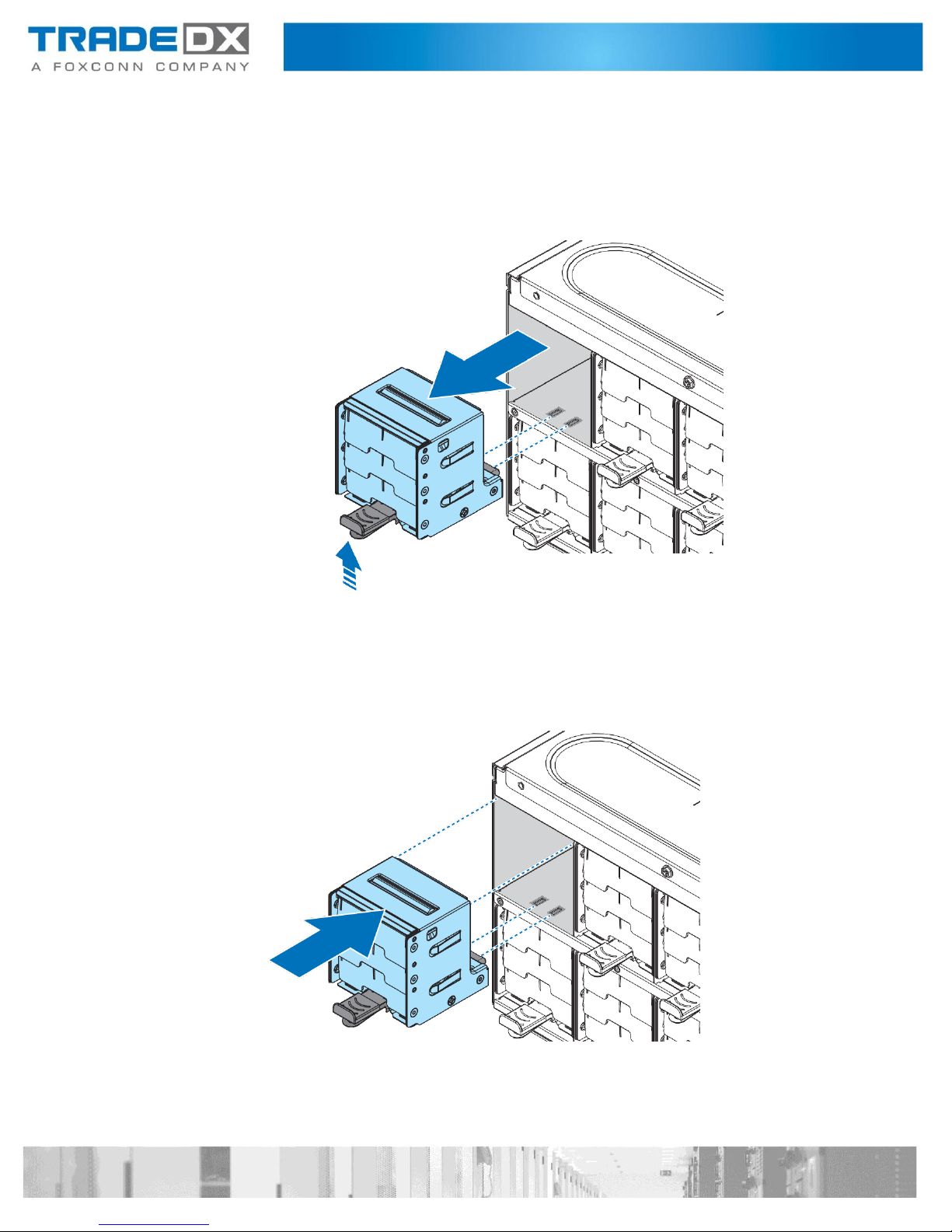
Chassis Management Module (CMM)
Removing a Chassis Management Module
Follow these steps to remove a CMM:
1. Open an HDD drawer. See “Opening an HDD Drawer” on page 13.
2. Loosen a thumb screw securing a CMM to the HDD drawer.
3. Disconnect a CMM from the HDD backplane.
Installing a Chassis Management Module
Follow these steps to install a CMM:
1. Align the connector on CMM with the connector on HDD backplane.
2. Install a CMM. Press down gently to seat in place.
3. Secure a CMM with a thumb screw.
4. Close an HDD drawer. See “Closing an HDD Drawer” on page 14.

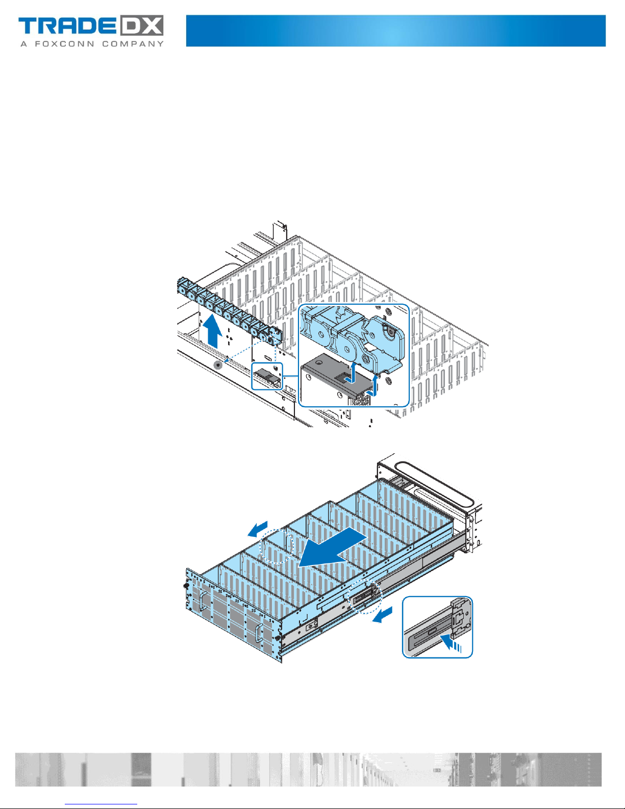
Inner Rail
Removing an Inner Rail
Follow these steps to remove an inner rail:
1. Power off the JBOD and detach all of the power cords from the power supply.
2. Open an HDD drawer. See “Opening an HDD Drawer” on page 13.
3. Remove the HDDs. See “Removing a 3.5” HDD” on page 30.
4. Remove the expander boards. See “Removing an Expander Board” on page 31.
5. Disconnect the cables from the HDD backplanes.
6. Remove an HDD drawer. See “Removing an HDD Drawer” on page 15.
7. Place an HDD drawer on a clean work space.
8. Remove the screws securing an inner rail to the HDD drawer.
9. Pull the latch upward and remove the keyhole from standoff.
10. Slide an inner rail forward to release and remove an inner rail.
11. Repeat the previous procedures for the additional inner rail.

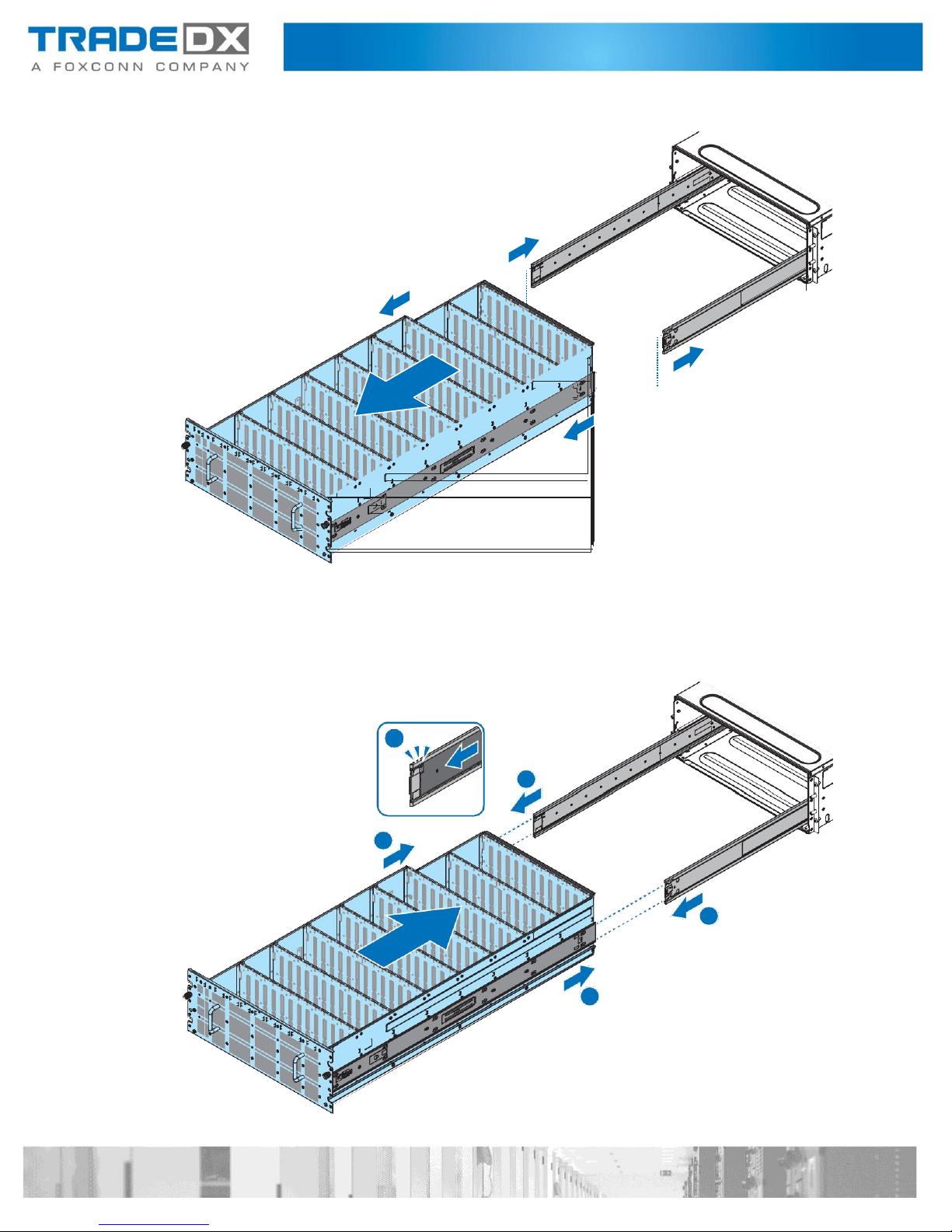
Installing an Inner Rail
Follow these steps to install an inner rail:
1. Align the keyholes on an inner rail with the standoffs on the HDD drawer.
Slide an inner rail backward so that the standoffs lock in place.
2. Secure an inner rail to the HDD drawer with screws.
3. Repeat the previous procedures for the additional inner rail.
4. Install an HDD drawer. See “Installing an HDD Drawer” on page 17.
5. Install the HDDs. See “Installing a 3.5” HDD” on page 28.
6. Close an HDD drawer. See “Closing an HDD Drawer” on page 14.

Rail Bracket
Removing a Rail Bracket
Follow these steps to remove a rail bracket:
1. Power off the JBOD and detach all of the power cords from the power supply.
2. Open an HDD drawer. See “Opening an HDD Drawer” on page 13.
3. Remove the HDDs. See “Removing a 3.5” HDD” on page 30.
4. Remove the expander boards. See “Removing an Expander Board” on page 31.
5. Disconnect the cables from the HDD backplanes.
6. Remove an HDD drawer. See “Removing an HDD Drawer” on page 15.
7. Turn an HDD drawer over and place an HDD drawer on a clean work space.
8. Remove the inner rail. See “Removing an Inner Rail” on page 48.
9. Remove the screws securing a rail bracket to an HDD drawer.
10. Remove a rail bracket.

Installing a Rail Bracket
Follow these steps to install a rail bracket:
1. Align the holes on a rail bracket with the pins on an HDD drawer.
2. Secure a rail bracket to an HDD drawer with screws.
3. Install the inner rail. See “Installing an Inner Rail” on page 49.
4. Turn an HDD drawer over.
5. Install an HDD drawer. See “Installing an HDD Drawer” on page 17.
6. Connect the cables to the HDD backplanes.
7. Install the expander boards. See “Installing an Expander Board” on page 33.
8. Install the HDDs. See “Installing a 3.5” HDD” on page 28.
9. Close an HDD drawer. See “Closing an HDD Drawer” on page 14.

HDD Backplane
Removing a HDD Backplane
Follow these steps to remove an HDD backplane:
1. Power off the JBOD and detach all of the power cords from the power supply.
2. Open an HDD drawer. See “Opening an HDD Drawer” on page 13.
3. Remove the HDDs. See “Removing a 3.5” HDD” on page 30.
4. Remove the expander boards. See “Removing an Expander Board” on page 31.
5. Disconnect the cables from the HDD backplanes.
6. Remove an HDD drawer. See “Removing an HDD Drawer” on page 15.
7. Turn an HDD drawer over and place an HDD drawer on a clean work space.
8. Remove the inner rail. See “Removing an Inner Rail” on page 48.
9. Remove a rail bracket. See “Removing a Rail Bracket” on page 50.
10. Disconnect the FFC cable from the HDD backplanes.
11. Remove the screws securing a strength panel to an HDD drawer.
12. Remove a strength panel.
13. Remove an HDD backplane.

14. Repeat the previous procedures for the additional HDD backplane.
Installing a HDD Backplane
Follow these steps to install an HDD backplane:
1. Align the holes on an HDD backplane with the pins on an HDD drawer.

2. Align the holes on a strength panel with the holes on an HDD drawer.
3. Secure a strength panel to an HDD drawer with screws.
4. Repeat the previous procedures for the additional HDD backplane.
5. Connect a FFC cable to the HDD backplanes.
6. Install a rail bracket. See “Installing a Rail Bracket” on page 51.
7. Install the inner rail. See “Installing an Inner Rail” on page 49.
8. Turn an HDD drawer over.
9. Install an HDD drawer. See “Installing an HDD Drawer” on page 17.
10. Connect the cables to the HDD backplanes.
11. Install the expander boards. See “Installing an Expander Board” on page 33.
12. Install the HDDs. See “Installing a 3.5” HDD” on page 28.
13. Close an HDD drawer. See “Closing an HDD Drawer” on page 14.
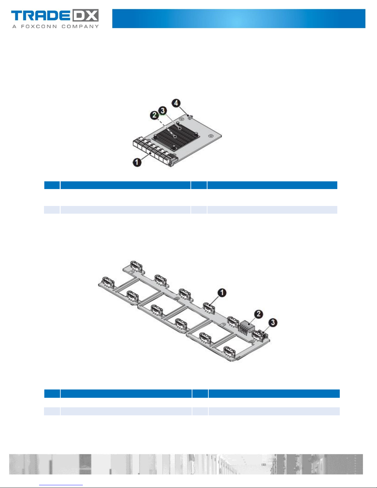
No
Item
No
Item
1
XCede high speed connector to HDD
backplane
2
Expander chipset
3
Expander chipset heat sink
4
Expander board fault LED
No
Item
No
Item
1
1 x 7-pin fan connector to fan x 12
2
2 x 6-pin power connector to PDB
3
2 x 10-pin signal connector to PDB
Connectors
Expander Boards
Fan Board

No
Item
No
Item
1
PSU connector x 2
2
2 x 6-pin power connector to fan board
3
2 x 10-pin signal connector to fan board
4
2 x 9-pin signal connector to HDD back-
plane 1
5
2 x 6-pin signal connector to RPB
6
2 x 8-pin signal connector to HDD back-
plane 2
7
2 x 10-pin power connector to HDD
backplane
No
Item
No
Item
1
PCIe x4 slot to CMM
2
Battery holder
3
2 x 10-pin power connector to PDB
4
2 x 9-pin signal connector to PDB
5
RJ45 to RPB
6
MiniSAS HD connector to RPB
7
1 x 40-pin FFC connector to HDD back-
plane 2
8
HDD connector x 55
9
XCede connector to expander board
Power Distribution Board
HDD Backplane 1

No
Item
No
Item
1
2 x 10-pin power connector to PDB
2
2 x 9-pin signal connector to PDB
3
MiniSAS HD connector to RPB
4
HDD connector x 53
5
XCede connector to expander board
6
1 x 40-pin FFC connector to HDD back-
plane 1
7
1 x 40-pin FFC connector to HDD back-
plane 2
8
HDD connector x 55
No
Item
No
Item
1
Internal management RJ45 to HDD
backplane 1
2
2 x 6-pin signal connector to PDB
3
Internal miniSAS HD connector to HDD 4
backplane
4
UID and system status LED
5
Power button with LED
6
UID button
7
External miniSAS HD connector x 4
8
Debug connector (USB type B)
9
External management RJ45 x 1
HDD Backplane 2
Rear Panel Board (RPB)

No
Item
No
Item
1
PCIe x4 gold finger to HDD backplane 1
2
BMC chipset
Chassis Managemnt Module (CMM)
Cabling
Power Cable Routing
Signal Cable Routing

Rackmount Installation
Removing a Chssis from the Rack
CAUTION:
This procedure requires at least two operators to hold and install the chassis.
Follow these steps to remove a chassis from the rack:
1. Power off the JBOD and detach all of the power cords from the power supply.
2. Open an HDD drawer. See “Opening an HDD Drawer” on page 13.
3. Remove the HDDs. See “Removing a 3.5” HDD” on page 30.
4. Remove the expander boards. See “Removing an Expander Board” on page 31.
5. Disconnect the cabling from the rear side of the chassis.
6. Remove the screws securing the chassis and the rack.
7. Hold the hand rails and pull the chassis out of the rack. Make sure to
completely support the chassis while removing to avoid injury or damaging
the equipment.

Installing a Chassis on the Rack
CAUTION:
This procedure requires at least two operators to hold and install the chassis.
Follow these steps to install a chassis on the rack:
1. Before you begin, make sure the rails are rails are properly installed on the
chassis and the rack. See “Installing the Rackmount Rails” on page 67.
2. Align the chassis with the rack. Make sure the chassis is positioned correctly and
the rear side of the chassis is facing the back of the rack cabinet.
3. If we are not installing HDDs:
4. Slide the chassis into the rack until it is flush with the rack posts.
5. Secure the chassis in the rack with screws.
6. If we are installing HDDs:
7. Slide the chassis halfway into the rack, making sure the rear top cover is accessible.
8. Install the expander boards. See “Installing an Expander Board” on page 33.
9. Install the HDDs. See “Installing a 3.5” HDD” on page 28.
10. Slide the chassis into the rack cabinet until the chassis is flush in the cabinet.
11. Secure the chassis in the rack with screws.

Removing the Rackmount Rails
Follow these steps to remove the rackmount rails:
1. Remove a chassis from the rack. See “Removing a Chassis from the Rack” on page 63.
2. Remove the screws securing the rear support brackets and the rack.
3. Remove the screws securing the rails to the rack.
4. Remove the rails from the rack.

5. Hold the bar nut to prevent it from dropping and remove the securing screw.
6. The bar nut is now free to remove.
Installing the Rackmount Rails
Follow these steps to install the rackmount rails:
1. Align the bar nut on the flange of the rail. The shape is designed to allow the
bar nut to sit flush with the flange.
2. Hold the bar nut in place and secure it with a screw.
3. Repeat for the remaining bar nuts.

1U
1U
1U
1U
1U
1U
1U
1U
4. First place the front side of the rails flush with the rail post.
5. Secure the front side of the rails and the rack with screws.
6. Extend the rear of the rail until the rear of the rail is flush with the rear side of the rear
rack post.
7. Secure the rear side of the rail in the rack with screws.
NOTE:
Screw (Ø 9.1 mm): square hole type posts.
Screw (Ø 6.8 mm): round hole type posts.

1U
1U
1U
1U
8. Align the support bracket with the rear post. Make sure the holes on the
support bracket are aligned with the bar nut, now located behind the post.
9. Secure the rear support brackets in the rack with screws.
10. Repeat for the remaining rail.

[root@localhost]# ipmitool -H 10.67.222.129 -U admin -P admin -I lanplus mc info
Device ID : 32
Device Revision : 1
Firmware Revision : 1.00
IPMI Version : 2.0
Manufacturer ID : 0
Manufacturer Name : Unknown
Product ID : 514 (0x0202)
Product Name : Unknown (0x202)
Device Available : yes
Provides Device SDRs : no
Additional Device Support :
Sensor Device
SDR Repository Device SEL
Device
FRU Inventory Device IPMB
Event Receiver IPMB Event
Generator Chassis Device
Aux Firmware Rev Info:
0x00
0x00
0x00
0x00
Configuration
Chassis Management Module (CMM)
IP Address
The CMM FW can be configured using Static or DHCP IP address settings. Set the IP address
by using the system management software --default setting is DHCP.
Username and Password
A username and password are required to establish a session. The user should also
have ac- cess to the same LAN subnet. Use the system management software to set
the username, password, and privileges. The default setting is shown below:
Username: admin
Password: admin
Updating the CMM Firmware
Many common problems can be resolved by updating the firmware. The CMM FW
can be up- dated through the Yafuflash host-based utility.
CMM FW Version
Normally, the end user must check the FW version before starting operations. By
using the standard IPMI command in the ipmitool utility, you can obtain CMM FW
information.
Command:
#ipmitool –H <ip address> -U <username> -P <password> -I lanplus mc info
Example:

CMM Image File Naming
File naming information: SHM<Major><Minor><SKU>.ima
SHM: Identifiers for specified product.
<Major>: Two characters for major version number.
<Minor>: Two characters for minor version number.
<SKU>: Single character for SKU identifier, typical “A”, “B”, ….
Example:
SHM0101A.ima: Image file for FW version 1.01.
Updating CMM FW Using Linux
1. Log into Linux.
2. Open the terminal.
3. Create a temporary folder /cmm.
4. Copy the Yafuflash utility and CMM FW images to the /cmm folder.
5. Since CMM supports dual-images, additional elements -mse <image selector> are
required.
-mse 1: Image 1 selected to be flashed,
-mse 2: Image 2 selected to be flashed,
6. Image 1 (first flash part) is the primary boot and active image after JBOD reset
or power on, the default flashed target is inactive (backup) image if without “mse” option. So specified the selec- tor is recommended.
7. Execute the following command to start the interactive CMM FW flash process.
Command:
Normal update mode (with interactive messages):
#./ Yafuflash –nw –ip <ip address> -u <usernam> –p <password> -mse < selector>
<FW filename>
Command for quiet update mode (without interactive messages):
#./ Yafuflash –nw –ip <ip address> -u <usernam> –p <password> -fb -mse <
selector> <FW filename>
or
#./ Yafuflash –nw –ip <ip address> -u <usernam> –p <password> -ipc -idi -iml -isi
-ibv-mse < selector> <FW filename>

ModuleName
Description Version
Version
Version
1. boot
BootLoader 2.3.000000
2.3.000000
2.3.000000
2. conf
ConfigParams
2.3.000000
2.3.000000
2.3.000000
3. bkupconf
2.3.000000
2.3.000000
2.3.000000
4. root
Root 2.1.000000
2.1.000000
2.1.000000
5. osimage
Linux OS 2.1.000000
2.1.000000
2.1.000000
6. www
Web Pages 2.1.000000
2.1.000000
2.1.000000
7. ast2500e
1.0.000000
1.0.000000
1.0.99
Existing Image
and Current Image are Same
Uploading Firmware Image :
100%...
done
Skipping [boot] Module ....
[root@localhost]# ./Yafuflash -nw -ip 10.67.222.129 -u admin -p admin -mse 1 SHM0100A.ima
INFO: Yafu INI Configuration File not found... Default options will not be applied...
Creating IPMI session via network with address 10.67.222.129...Done
-------------------------------------------------
YAFUFlash - Firmware Upgrade Utility (Version 4.89.0)
-------------------------------------------------
(C)Copyright 2016, American Megatrends Inc.
Image To be updated is (Image-1)
Example:
1. Specified Image-1 (active) to be flashed.
=============================================================================
Firmware Details
=============================================================================
RomImage Image 1 Image 2
So,Type (Y/y) to do Full Firmware Upgrade or (N/n) to exit
Enter your Option : y
****************************************************************************
WARNING!
PLEASE DO NOT USE THIS FLASH TOOL FROM THE REDIRECTION CONSOLE.
****************************************************************************
FIRMWARE UPGRADE MUST NOT BE INTERRUPTED ONCE IT IS STARTED.

Flashing [conf] Module ....
Flashing Firmware Image :
100%...
done
Verifying Firmware Image :
100%...
done
Flashing [bkupconf] Module
....
Flashing Firmware Image :
100%...
done
Verifying Firmware Image :
100%...
done
Flashing [root] Module ....
Flashing Firmware Image : 100%... done
Verifying Firmware Image : 100%... done
Flashing [osimage] Module ....
Flashing Firmware Image : 100%... done
Verifying Firmware Image : 100%... done
Flashing [www] Module ....
Flashing Firmware Image : 100%... done
Verifying Firmware Image : 100%... done
Flashing [ast2500e] Module ....
Flashing Firmware Image : 100%... done
Verifying Firmware Image : 100%... done
Resetting the firmware..........

Uploading Firmware Image :
100%...
done
Skipping [boot] Module ....
Flashing [conf] Module ....
Flashing Firmware Image :
100%...
done
Verifying Firmware Image :
100%...
done
Flashing [bkupconf] Module
....
Flashing Firmware Image :
100%...
done
Verifying Firmware Image :
100%...
done
Flashing [root] Module ....
Flashing Firmware Image : 100%... done
Verifying Firmware Image : 100%... done
Flashing [osimage] Module ....
Flashing Firmware Image : 100%... done
Verifying Firmware Image : 100%... done
Flashing [www] Module ....
Flashing Firmware Image : 100%... done
Verifying Firmware Image : 100%... done
Flashing [ast2500e] Module ....
Flashing Firmware Image : 100%... done
Verifying Firmware Image : 100%... done
Resetting the firmware..........
2. Specified Image-2 (inactive) to be flashed.
[root@localhost]# ./Yafuflash -nw -ip 10.67.222.129 -u admin -p admin -mse 2 SHM0100A.ima
INFO: Yafu INI Configuration File not found... Default options will not
be applied...
Creating IPMI session via network with address 10.67.222.129...Done
-------------------------------------------------
YAFUFlash - Firmware Upgrade Utility (Version 4.89.0)
-------------------------------------------------
(C)Copyright 2016, American Megatrends Inc.
Image to be updated is (Image-2)
The Module osimage size is different from the one in the
Image So,Type (Y/y) to do Full Firmware Upgrade or (N/n)
to exit Enter your Option : y
****************************************************************************
WARNING!
FIRMWARE UPGRADE MUST NOT BE INTERRUPTED ONCE IT IS STARTED.
PLEASE DO NOT USE THIS FLASH TOOL FROM THE REDIRECTION CONSOLE.
****************************************************************************

[root@localhost]# ipmitool -H 10.67.222.129 -U admin -P admin -I lanplus mc info
Device ID : 32
Device Revision : 1
Firmware Revision : 1.00
IPMI Version : 2.0
Manufacturer ID : 0
Manufacturer Name : Unknown
Product ID : 514 (0x0202)
Product Name : Unknown (0x202)
Device Available : yes
Provides Device SDRs : no
Additional Device Support :
Sensor Device
SDR Repository Device SEL
Device
FRU Inventory Device IPMB
Event Receiver IPMB Event
Generator Chassis Device
Aux Firmware Rev Info :
0x00
0x00
0x00
0x00
Checking the CMM FW Version Using Linux
1. Log into the Linux terminal.
2. Open the terminal. Execute the ipmitool command to display the FW version as shown in
the following figure.
Command:
#ipmitool –H <ip address> -U <username> -P <password> -I lanplus mc info
Example:
Checking the System Event Log Using Linux
1. Log into the Linux terminal.
2. Open the terminal. Execute the ipmitool command to display the system event log (SEL)
as shown in the following figure.
Command:
#ipmitool –H <ip address> -U <username> -P <password> -I lanplus sel list
#ipmitool –H <ip address> -U <username> -P <password> -I lanplus sel get
<re- cord>

Module
LED Indicator
LED
color
LED condition
Description
SAS Wide-
Port
SAS Link LED
Green
ON
SAS Link Up
OFF
SAS Link Down
SAS Status LED
Amber
ON
Data Transmission
OFF
No Data
Transmission
Online/ Present
LED
Blue
ON
HDD is present
OFF
HDD is not Present
HDD
Locate/ Fault
Red
ON
Failed
OFF
Normal
Blinking (4Hz)
Identifier
Blinking (long-short-
short)
HDD slot power is
off
List All Sensors and Status Using Linux
1. Log into the Linux terminal.
2. Open the terminal. Execute the ipmitool command to display all supported sensors as
shown in the following figure.
Command:
#ipmitool –H <ip address> -U <username> -P <password> -I lanplus sensor
Storage Drive LEDs
The system LED is used to show the state of the enclosure. The following table lists
storage LED indicators in the system.
Updating Expander Board Firmware
Updating expander firmware can fix related problems with the storage system. The
expander firmware can be updated through a host based utility – g3Xflash.

[root@expander]# ./g3Xflash -i get avail
********************************************************************************
g3Xflash
Expander Flash Utility
Version: 14.1.0.0
Copyright 2016 Avago Technologies. All rights reserved.
********************************************************************************
Initializing Interface.
Expander: SledgeHammer_2 (SAS_35X_36)
1) SledgeHammer_2 (SAS_35X_36) (51C666DF:B6CB203F)
2) SledgeHammer_0 (SAS_35X_36) (51C666DF:B6CB803F)
3) SledgeHammer_1 (SAS_35X_36) (51C666DF:B6CB903F)
4) SledgeHammer_3 (SAS_35X_36) (51C666DF:B6CB303F)
[root@expander]# ./g3Xflash -i 51C666DFB6CB203F down fw Expander-Firmware_Image_
v0.0.0.2_20170223.fw 1 -y
********************************************************************************
******************************************************************************** Initializing
Interface.
Expander: SledgeHammer_2 (SAS_35X_36)
Target Firmware Region: 01
Pre-Validation of image is successful.
Downloading File...........Download Complete.
Post-validating.......Post-Validation of image is successful.
Download Successful.
Updating Expander Board Firmware Using Linux
To update expander board firmware using Linux:
1. Log into the Linux terminal.
2. Open the terminal.
3. Create a temporary folder /expander.
4. Copy the g3Xflash utility and expander FW/MFG images to the /expander folder.
5. Execute the following command to scan the expander device and obtain four
expander SAS addresses: ./g3Xflash -i get avail.
6. Execute the following commands to update expander firmware images for whole
expanders: ./g3Xflash –i <SAS Address> down fw <Expander Firmware image> 1 -y.
g3Xflash
Expander Flash Utility
Version: 14.1.0.0
Copyright 2016 Avago Technologies. All rights reserved.
Expander Validation: Passed
Checksum: Passed
Current Version: 00.00.00.01
Replacement Version: 00.00.00.02
Image Validation: Passed

[root@expander]# ./g3Xflash -i 51C666DFB6CB803F down fw Expander-Firmware_Image_
v0.0.0.2_20170223.fw 1 -y
********************************************************************************
g3Xflash
Expander Flash Utility Version: 14.1.0.0
Copyright 2016 Avago Technologies. All rights reserved.
**************************************************************************Initializing
Interface.
Expander: SledgeHammer_0 (SAS_35X_36)
Expander Validation: Passed
Checksum: Passed
Target Firmware Region: 01
Current Version: 00.00.00.01
Replacement Version: 00.00.00.02
Image Validation: Passed
Pre-Validation of image is successful.
Downloading File...........
Download Complete.
Post-validating.......Post-Validation of image is successful.
Download Successful.
[root@expander]# ./g3Xflash -i 51C666DFB6CB903F down fw Expander-Firmware_Image_
v0.0.0.2_20170223.fw 1 -y
********************************************************************************
g3Xflash
Expander Flash Utility Version: 14.1.0.0
Copyright 2016 Avago Technologies. All rights reserved.
**************************************************************************Initializing
Interface.
Expander: SledgeHammer_1 (SAS_35X_36)
Expander Validation: Passed
Checksum: Passed
Target Firmware Region: 01
Current Version: 00.00.00.01
Replacement Version: 00.00.00.02
Image Validation: Passed
Pre-Validation of image is successful.
Downloading File...........
Download Complete.
Post-validating.......Post-Validation of image is
successful. Download Successful.
[root@expander]# ./g3Xflash -i 51C666DFB6CB303F down fw Expander-Firmware_Image_
v0.0.0.2_20170223.fw 1 –y
********************************************************************************

g3Xflash
Expander Flash Utility Version: 14.1.0.0
Copyright 2016 Avago Technologies. All rights reserved.
********************************************************************************
Initializing Interface.
Expander: SledgeHammer_3 (SAS_35X_36)
Expander Validation: Passed
Checksum: Passed
Target Firmware Region: 01
Current Version: 00.00.00.01
Replacement Version: 00.00.00.02
Image Validation: Passed
Pre-Validation of image is successful.
Downloading File...........
Download Complete.
Post-validating.......Post-Validation of image is successful.
Download Successful.
7. Execute the following commands to update the Expander manufacture configuration
image for whole Expanders: ./g3Xflash –i <SAS Address> down mfg <Expander MFG
image> 3 -y.
[root@expander]# ./g3Xflash -i 51C666DFB6CB203F down mfg Expander-MFG_Image_
v0.0.0.2_20170223.bin 3 -y
********************************************************************************
g3Xflash
Expander Flash Utility
Version: 14.1.0.0
Copyright 2016 Avago Technologies. All rights reserved.
********************************************************************************
Initializing Interface.
Expander: SledgeHammer_2 (SAS_35X_36)
Image Validation: Passed
Checksum: Passed
Current Version: 00.01
Replacement Version: 00.02
Pre-Validation of image is successful.
Downloading File...
Download Complete.
Post-validating.......Post-Validation of image is successful.
Download Successful.
[root@expander]# ./g3Xflash -i 51C666DFB6CB803F down mfg Expander-MFG_Image_
v0.0.0.2_20170223.bin 3 -y
********************************************************************************
g3Xflash
Expander Flash Utility
Version: 14.1.0.0
Copyright 2016 Avago Technologies. All rights reserved.
********************************************************************************

Initializing Interface.
Expander: SledgeHammer_0 (SAS_35X_36)
Image Validation: Passed
Checksum: Passed Current
Version: 00.01
Replacement Version: 00.02
Pre-Validation of image is successful.
Downloading File...
Download Complete.
Post-validating.......Post-Validation of image is successful.
Download Successful.
[root@expander]# ./g3Xflash -i 51C666DFB6CB903F down mfg Expander-MFG_Image_
v0.0.0.2_20170223.bin 3 -y
********************************************************************************
g3Xflash
Expander Flash Utility
Version: 14.1.0.0
Copyright 2016 Avago Technologies. All rights reserved.
********************************************************************************
Initializing Interface.
Expander: SledgeHammer_1 (SAS_35X_36)
Image Validation: Passed
Checksum: Passed
Current Version: 00.01
Replacement Version: 00.02
Pre-Validation of image is successful.
Downloading File..…
Download Complete.
Post-validating.......Post-Validation of image is successful.
Download Successful.
[root@expander]# ./g3Xflash -i 51C666DFB6CB303F down mfg Expander-MFG_Image_
v0.0.0.2_20170223.bin 3 -y
********************************************************************************
g3Xflash
Expander Flash Utility
Version: 14.1.0.0
Copyright 2016 Avago Technologies. All rights reserved.
********************************************************************************
Initializing Interface.
Expander: SledgeHammer_3 (SAS_35X_36)
Image Validation: Passed
Checksum: Passed
Current Version: 00.01
Replacement Version: 00.02

Pre-Validation of image is successful.
Downloading File...
Download Complete.
Post-validating.......Post-Validation of image is successful.
Download Successful.
8. Execute the following command to reset whole Expanders: ./g3Xflash –i <SAS
[root@expander]# ./g3Xflash -i 51C666DFB6CB203F reset exp -y
Address> re- set exp –y.
********************************************************************************
g3Xflash
Expander Flash Utility
Version: 14.1.0.0
Copyright 2016 Avago Technologies. All rights reserved.
********************************************************************************
Initializing Interface.
Expander: SledgeHammer_2 (SAS_35X_36)
Expander reset request successfully sent to expander.
[root@expander]# ./g3Xflash -i 51C666DFB6CB803F reset exp -y
********************************************************************************
g3Xflash
Expander Flash Utility
Version: 14.1.0.0
Copyright 2016 Avago Technologies. All rights reserved.
********************************************************************************
Initializing Interface.
Expander: SledgeHammer_0 (SAS_35X_36)
Expander reset request successfully sent to expander.
[root@expander]# ./g3Xflash -i 51C666DFB6CB903F reset exp -y
********************************************************************************
g3Xflash
Expander Flash Utility
Version: 14.1.0.0
Copyright 2016 Avago Technologies. All rights reserved.
********************************************************************************
Initializing Interface.
Expander: SledgeHammer_1 (SAS_35X_36)
Expander reset request successfully sent to expander.
[root@expander]# ./g3Xflash -i 51C666DFB6CB303F reset exp -y

[root@expander]# ./g3Xflash -i get avail
********************************************************************************
g3Xflash
Expander Flash Utility
Version: 14.1.0.0
Copyright 2016 Avago Technologies. All rights reserved.
********************************************************************************
Initializing Interface.
Expander: SledgeHammer_2 (SAS_35X_36)
1) SledgeHammer_2 (SAS_35X_36) (51C666DF:B6CB203F)
2) SledgeHammer_0 (SAS_35X_36) (51C666DF:B6CB803F)
3) SledgeHammer_1 (SAS_35X_36) (51C666DF:B6CB903F)
4) SledgeHammer_3 (SAS_35X_36) (51C666DF:B6CB303F)
********************************************************************************
g3Xflash
Expander Flash Utility
Version: 14.1.0.0
Copyright 2016 Avago Technologies. All rights reserved.
********************************************************************************
Initializing Interface.
Expander: SledgeHammer_3 (SAS_35X_36)
Expander reset request successfully sent to expander.
Note:
Please add -w parameter for non-disruptive firmware update to avoid SAS I/O interrupt.
User may need to execute above commands at the same time to avoid runtime version
compatibility/inconsist- ent issue or Linux driver noisy messages.
Checking Expander Version Using Linux
To check the expander firmware version using Linux:
1. Log into the Linux terminal.
2. Open the Terminal.
3. Create a temporary folder /expander.
4. Copy g3Xflash utility to /expander folder.
5. Execute the following command to scan expander devices and obtain four
Expander SAS addresses: ./g3Xflash -i get avail.

6. Execute the following commands to get runtime/active firmware versions of whole.
Expanders by SAS address: ./g3Xflash –i <SAS Address> get ver.
[root@expander]# ./g3Xflash -i 51C666DFB6CB203F get ver
********************************************************************************
g3Xflash
Expander Flash Utility
Version: 14.1.0.0
Copyright 2016 Avago Technologies. All rights reserved.
********************************************************************************
Initializing Interface.
Expander: SledgeHammer_2 (SAS_35X_36)
Firmware Region Version: 00.00.00.02
[root@expander]# ./g3Xflash -i 51C666DFB6CB803F get ver
********************************************************************************
g3Xflash
Expander Flash Utility
Version: 14.1.0.0
Copyright 2016 Avago Technologies. All rights reserved.
********************************************************************************
Initializing Interface.
Expander: SledgeHammer_0 (SAS_35X_36)
Firmware Region Version: 00.00.00.02
[root@expander]# ./g3Xflash -i 51C666DFB6CB903F get ver
********************************************************************************
g3Xflash
Expander Flash Utility
Version: 14.1.0.0
Copyright 2016 Avago Technologies. All rights reserved.
********************************************************************************
Initializing Interface.
Expander: SledgeHammer_1 (SAS_35X_36)
Firmware Region Version: 00.00.00.02
[root@expander]# ./g3Xflash -i 51C666DFB6CB303F get ver
********************************************************************************
g3Xflash
Expander Flash Utility
Version: 14.1.0.0
Copyright 2016 Avago Technologies. All rights reserved.
********************************************************************************
Initializing Interface.
Expander: SledgeHammer_3 (SAS_35X_36)
Firmware Region Version: 00.00.00.02

7. Execute the following commands to get manufacture configuration image
versions of whole Expanders by SAS address: ./g3Xflash –i <SAS Address>
get ver 3.
[root@expander]# ./g3Xflash -i 51C666DFB6CB203F get ver 3
********************************************************************************
g3Xflash
Expander Flash Utility
Version: 14.1.0.0
Copyright 2016 Avago Technologies. All rights reserved.
********************************************************************************
Initializing Interface.
Expander: SledgeHammer_2 (SAS_35X_36)
Reading the MFG Version Info page........
Product Id : 48
Platform Id : 00
FW Version : 00.00.00.02
MFG Version : 00.02
Platform Version : 00.00
Product Name :FOXCONN JBOD
Platform Name : SledgeHammer_EXP2
[root@expander]# ./g3Xflash -i 51C666DFB6CB203F get ver 3
********************************************************************************
g3Xflash
Expander Flash Utility
Version: 14.1.0.0
Copyright 2016 Avago Technologies. All rights reserved.
********************************************************************************
Initializing Interface.
Expander: SledgeHammer_2 (SAS_35X_36)
Reading the MFG Version Info page........
Product Id : 48
Platform Id : 00
FW Version : 00.00.00.02
MFG Version : 00.02
Platform Version : 00.00
Product Name :FOXCONN JBOD
Platform Name : SledgeHammer_EXP0
[root@expander]# ./g3Xflash -i 51C666DFB6CB203F get ver 3
********************************************************************************
g3Xflash
Expander Flash Utility
Version: 14.1.0.0
Copyright 2016 Avago Technologies. All rights reserved.
********************************************************************************

Initializing Interface.
Expander: SledgeHammer_2 (SAS_35X_36)
Reading the MFG Version Info page........
Product Id : 48
Platform Id : 00
FW Version : 00.00.00.02
MFG Version : 00.02
Platform Version : 00.00
Product Name :FOXCONN JBOD
Platform Name : SledgeHammer_EXP1
[root@expander]# ./g3Xflash -i 51C666DFB6CB203F get ver 3
********************************************************************************
g3Xflash
Expander Flash Utility
Version: 14.1.0.0
Copyright 2016 Avago Technologies. All rights reserved.
********************************************************************************
Initializing Interface.
Expander: SledgeHammer_2 (SAS_35X_36)
Reading the MFG Version Info page........
Product Id : 48
Platform Id : 00
FW Version : 00.00.00.02
MFG Version : 00.02
Platform Version : 00.00
Product Name :FOXCONN JBOD
Platform Name : SledgeHammer_EXP2
Component
Description
Form factor, chassis
4U JBOD chassis
Chassis dimensions (W x H x D)
448.9 x 175.6 x 985 mm (17.67 x 6.91 x 38.78 inch.)
Drive bays
Hot plug 3.5” HDD x 108
Rear I/O
External management RJ45 x 1
Debug connector (USB type B) x 1
External miniSAS HD connector x 4
UID button
Power button with LED
UID and system status LED
Power supply
PSU x 2 (1600W AC)
Rated voltage: 200-240V
Rated current: 40A
Rated frequency: 50/60Hz
System cooling fan
Hot plug 60 x 38 fan x 12
Environmental Specifications
Operating Temperature
5° C to 35° C
Non- operating Temperature
-40° C to 70° C
Non-operating Relative Humidity
40° C/ 93% RH
Specification
Before You Contact TradeDX
Be sure to have the following information available before you call TradeDX:
Technical support registration number (if applicable)
Product serial number
Product model name and number
Applicable error messages
Add-on boards or hardware
Third-party hardware or software
Operating system type and revision level

Contact
Address:
TradeDX s.r.o.
Karlov 245
284 01, Kutná Hora
Czech Republic
To contact TradeDX by a phone, call 00420737264041
For other contact information, please visit website: www.tradedx.eu/contacts
 Loading...