


Storage Carrier
User Manual
The information contained herein is subject to change without notice. The only warranties for TradedDX products
and services are set forth in the express warranty statements accompanying such products and services. Nothing
herein should be construed as constituting an additional warranty. TradeDX shall not be liable for technical
or editorial errors or omissions contained herein.

The information contained herein is subject to change without notice. The only warranties for TradeDX products
and services are set forth in the express warranty statements accompanying such products and services. Nothing
herein should be construed as constituting an additional warranty. TradeDX shall not be liable for technical
or editorial errors or omissions contained herein.

Contents
Component identification .................................................. 5
Front panel components ............................................................ 6
Front panel LEDs and buttons ...................................................... 6
Rear panel components ............................................................. 7
EEB module ........................................................................ 7
System LEDs ....................................................................... 8
Power supply LEDs ................................................................. 9
Operations ............................................................... 10
Powering on ...................................................................... 10
Powering down .................................................................... 10
Verifying the power status .................................................. 10
Installation ............................................................. 11
Safety measures .................................................................. 11
Identifying the contents of the Storage Carrier shipping carton ................. 11
Hard disk drives ................................................................. 12
Removing the Hard Disk Drive ................................................ 12
Installing the Hard Disk Drive.............................................. 13
HDD matrix ....................................................................... 14
Power supply units ............................................................... 14
Removing the power supply unit.............................................. 14
Installing the Redundant Power Supply Unit ................................. 15
System Architecture ...................................................... 16
Storage Carrier SAS dual path .................................................... 16
................................................................................. 16
Storage Carrier SATA single path ................................................. 16
Backplane Expander Board (BEB) ................................................... 17
Installing a Backplane Expander Board (BEB) ..................................... 18
Front Control Module ............................................................. 19
Removing the Front Control Module ................................................ 19
Installing the Front Control Module .............................................. 21
External Expander Board (EEB) .................................................... 23
Supported External Expander Boards ............................................... 23
Removing the External Expander Board (EEB) ...................................... 25
Installing the External Expander Board (EEB) .................................... 26
Fans ............................................................................. 28
Removing the System Fan .......................................................... 28
Installing the System Fan ........................................................ 28
Removing the System Fan (for PSU Cooling)........................................ 29
Installing the System Fan (for PSU Cooling) ..................................... 29
Power Distribution Board (PDB) ................................................... 30
Removing the Power Distribution Board (PDB) ..................................... 30
Installing the Power Distribution Board (PDB) ................................... 32
Mid-plane ........................................................................ 34
Removing the Mid-plane ........................................................... 34
Installing the Mid-plane ......................................................... 35
Power Interface Board (PIB) ...................................................... 36
Removing the Power Interface Board (PIB):........................................ 36
Regulatory information ................................................... 74
Class A .......................................................................... 74
European Union regulatory notice ................................................. 74
Safety ........................................................................... 74
3

Warnings & Safety/ ....................................................... 75
Important safety and compliance information .............................. 75
Safety precautions .......................................................... 75
Safety Instructions ......................................................... 75
Symbols .......................................................................... 76
Safety statements ................................................................ 77
Warnings and cautions ............................................................ 79
Electrostatic discharge .......................................................... 80
Specifications ........................................................... 81
Environmental specifications ..................................................... 81
Mechanical specifications ........................................................ 81
Support information ...................................................... 81
Customer support ................................................................. 81
Before you contact TradeDX ....................................................... 82
4
5
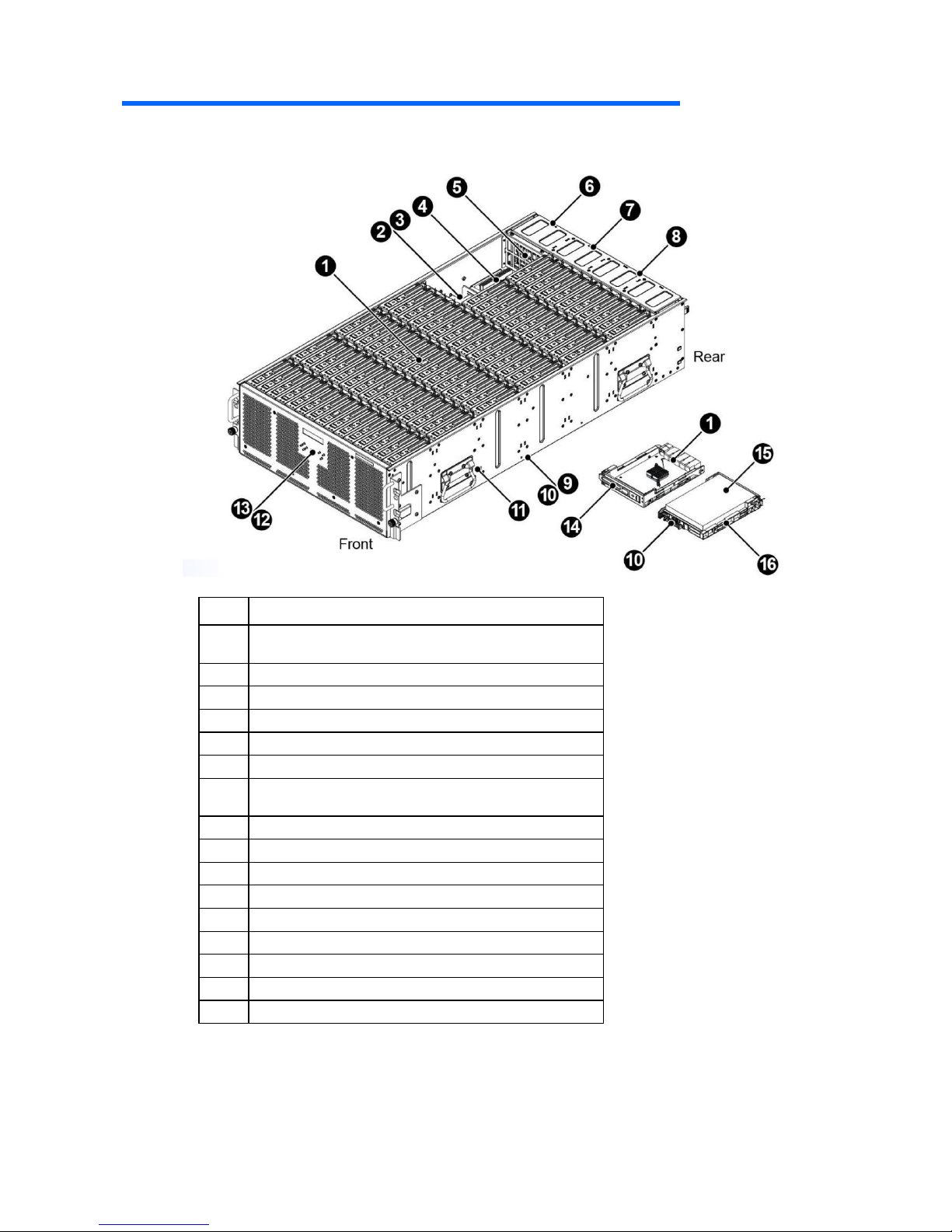
Component identification
Item
Description
1
BEB module x3 (SATA single path)
BEB module x6 (SAS dual path)
2
Power interface board
3
PSU Fan
4
Power distribution boards
5
Mid- plane
6
Power supply unit
7
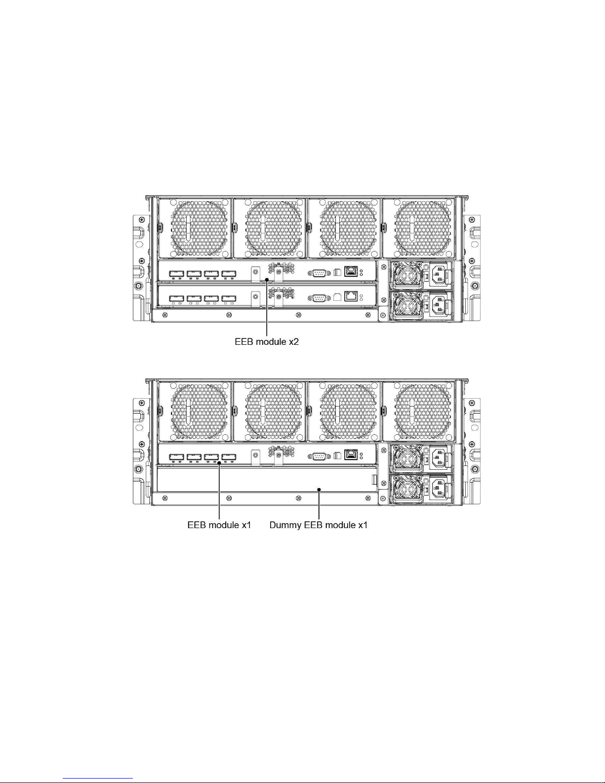
EEB module x1 (SATA single path)
EEB module x2 (SAS dual path)
8
System Fans
9
HDD backplane
10
SAS interposer board
11
4U chassis
12
Fron panel board
13
LCD module
14
BEB carrier
15
SAS/ SATA HDD
16
SAS/ SATA HDD Carrier
6
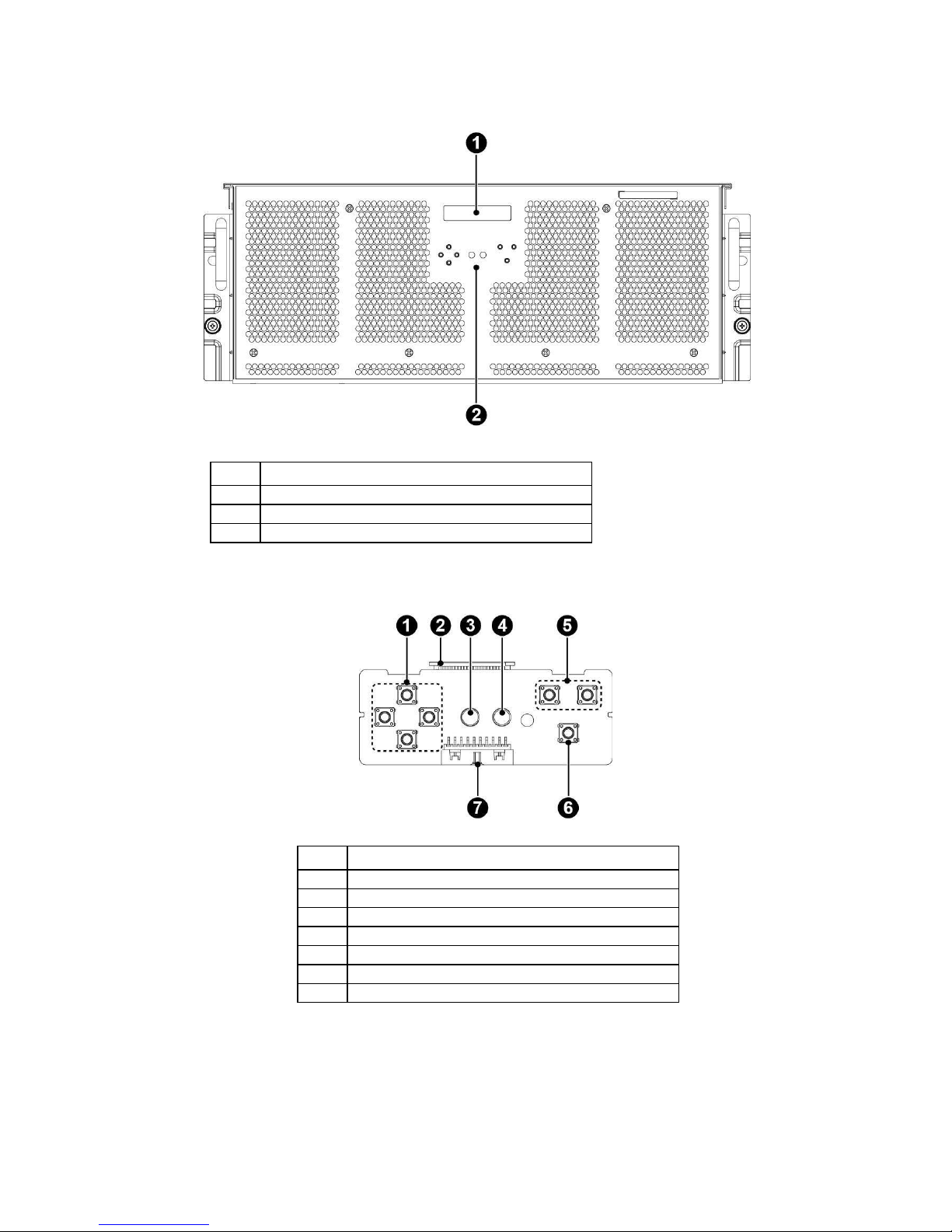
Front panel components
Front panel LEDs and buttons
Item
Description
1
LCD control buttons
2
LCD connector
3
UID LED
4
System Status LED
5
LCD control buttons
6
Power button
7
Fron panel board connector
Item
Description
1
LCD Module
2
Front panel board
3
Front control board
7
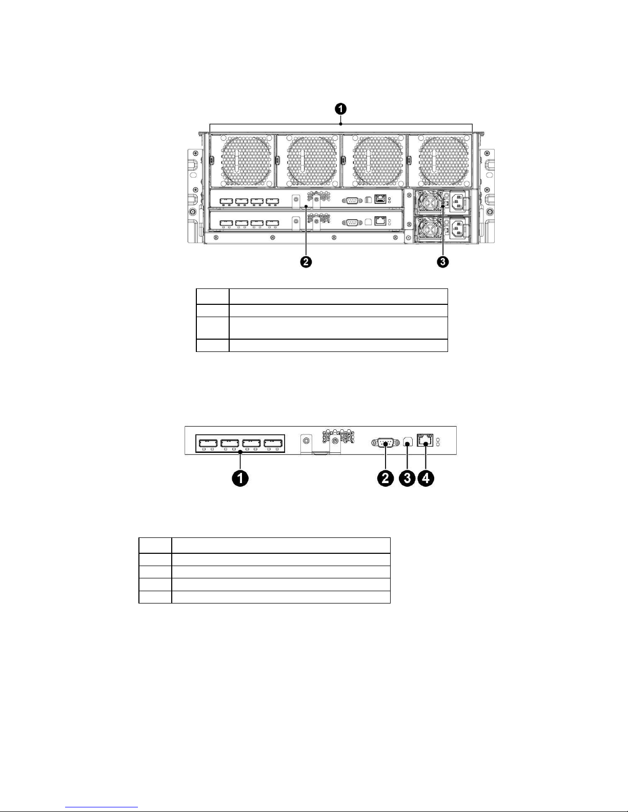
Rear panel components
Item
Description
1
System fans
2
EEB module x1 (SATA single path)
EEB module x2 (SAS dual path)
3
Power supply units
EEB module
Item
Description
1
External SAS ports
2
COM port
3
USB port
4
LAN port
8
System LEDs
Module
LED
Color
Condition
Description
Name
Front Panel
UID LED
Blue
Blinking
Enclosure identification
Blink on and off
System stand-by
rapidly
On
System power on
System Status
Red
On
System fault
LED
Blinking
System warning
Off
System good
UID LED/System
Red/
Intermittent
Firmware updating
Status LED
Blue
blinking
EEB
Status LED
Amber
On
EEB fault
Intermittent
FW Updating
blinking
Rapid blinking
System warning
Off
Normal
Identify LED
Blue
On
EEB firmware ready
Master EEB identification
Blinking
EEB identification
Off
Normal
SAS Link/Status
Green/
On (Green)
SAS link on
LED
Amber
Off (Amber)
Off (Green)
SAS link down
Off (Amber)
On (Green)
SAS link with activity
Blink (Amber)
BEB
Status LED
Amber
On
BEB fault
Intermitent
FW Updating
blinking
Rapid blinking
System warning
Off
Normal
Identify LED
Blue
On
BEB firmware ready
Blinking
BEB identify
Off
Normal
9
Module
LED
Color
Condition
Description
Name
HDD
Activity LED
Blue
On
HDD present, no activity
Blinking
HDD activity
Off
HDD not present
Locate/Fault LED
Amber
On
HDD fail
Intermittent
HDD rebuild
blinking
Off
Normal
Green
On
HDD hot sparing
Rapid blinking
HDD identify
Off
Normal
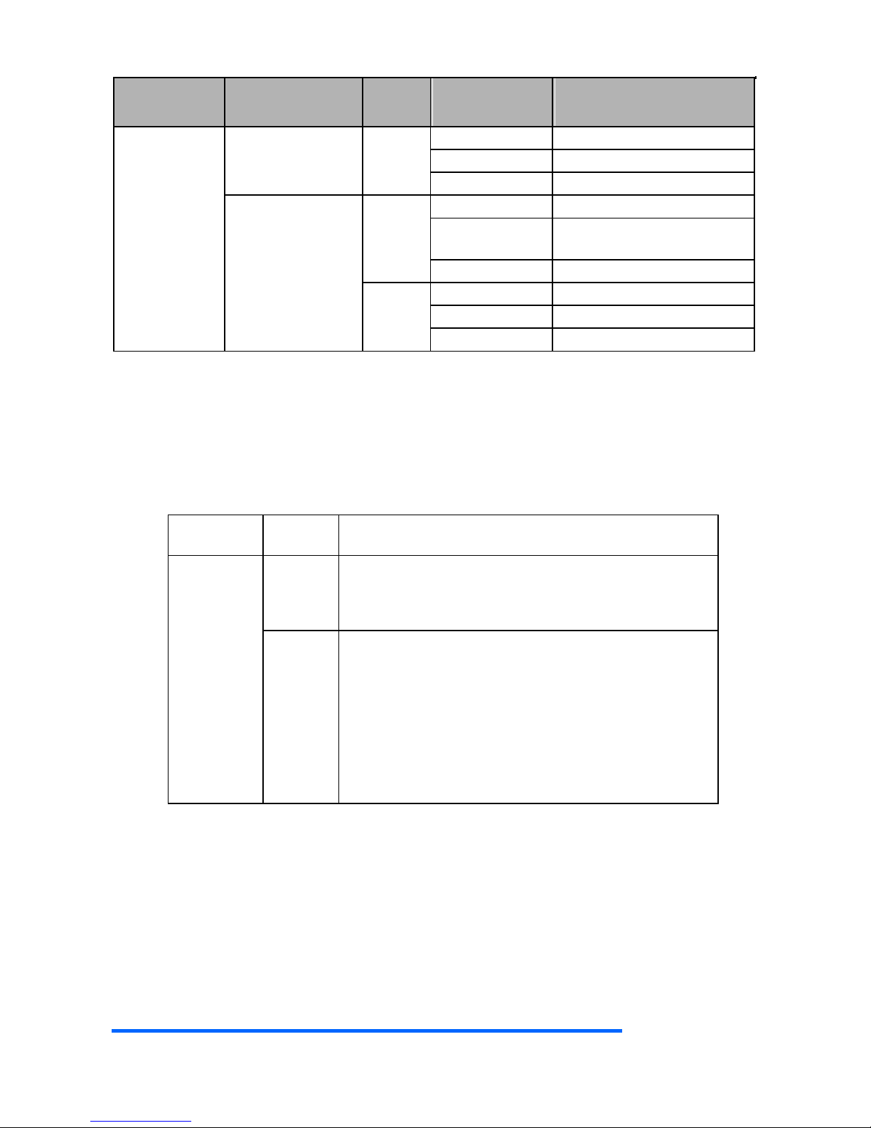
Power supply LEDs
The 1600W power supply comes with one LED and the LED is
visible from the rear of the power supply.
LED Staate
LED
Color
Description
AC Power
Green
On: Normal work
Off: No AC power to all power supplies
Blink (1Hz): AC present / Only 12VSB on (PS off) or
PS in CR state
Red
On:
o AC cord unplugged; with a second power
supply in parallel still with AC input power
o Power supply critical event causing a
shutdown; failure, OCP, OVP, Fan Fail
Blink (1Hz): Power supply warning events where the
power supply continues to operate; high temp, high
power, high current, slow fan, input voltage lower
than 90Vac (not warning above 90V condition, must
be warning state below 85V condition)

10
Operations
Powering on
Please follow these steps to turn on the system
1. Connect the power cord to the power socket at the rear
of the Storage Carrier and plug the other end into a
power outlet
2. Press the power button onc to turn on the Storage Carrier
Powering down
Please follow these steps to power down the system
1. Press and hold the power button and to turn off the
Storage Carrier
2. Disconnect the power cord from the power outlet
Verifying the power status
Verify all power LED indicators of the server and make sure
the power LED light is off before replacing and removing
the server components from the rack.

11
Installation
Safety measures
Static electricity discharges can damage computer
components and electronic circuit boards. Working on
computers that are still connected to a power supply can
be extremely dangerous. Follow these guidelines to avoid
self-injury and damage to the computer:
Always disconnect the Storage Carrier from the power
outlet when working inside of the computer case.
If possible, wear a grounded wrist strap when working
inside the computer case. Alternatively, discharge any
static electricity by touching the bare metal chassis
of the computer case, or the bare metal body of any other
grounded appliance.
Hold electronic circuit boards only by the edges. Do not
touch the components on the board unless it is necessary
to do so. Do not flex or stress the circuit board.
Leave all components inside the static-proof packaging
until ready to use the component for the installation.
Identifying the contents of
the Storage Carrier shipping
carton
Unpack the server shipping carton and locate the materials
for installing the server.
The contents of the server shipping carton include:
Storage carrier
Power cord
Rack-mounting hardware
In addition to the supplied items, you might need:
Hardware options
12
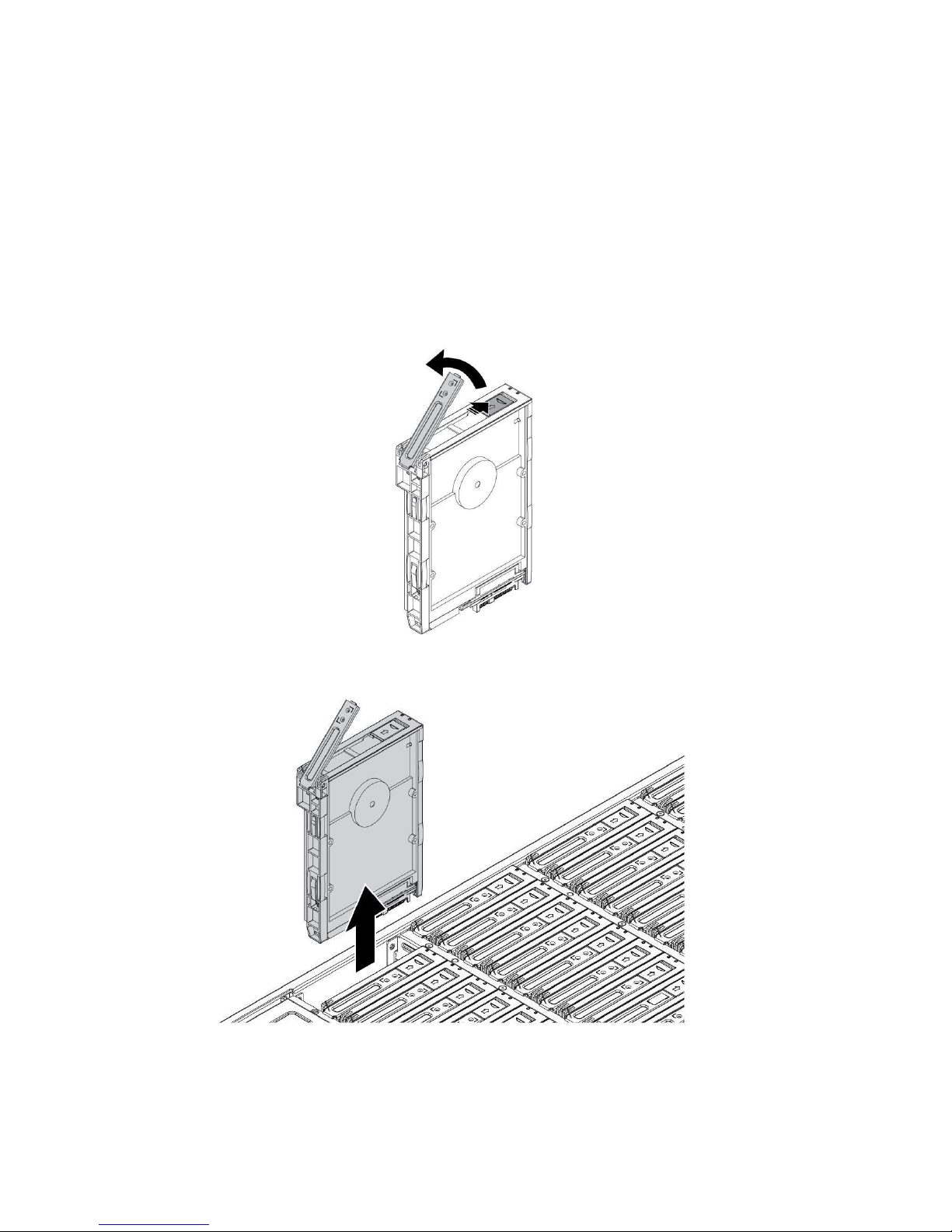
Hard disk drives
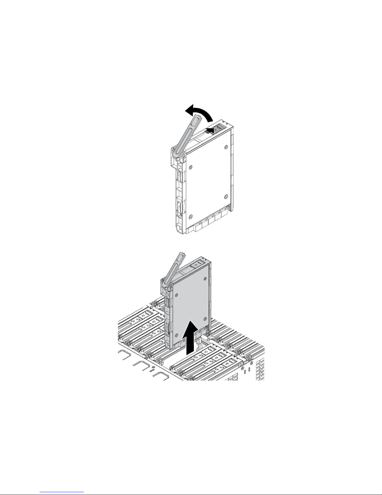
Removing the Hard Disk Drive
CAUTION!
Hard disks that require maintenance can be removed while the
server is operating normally. However, do not simultaneously remove
multiple hard disks. You can only remove one hard drive at a time
and for no longer than 10 minutes.
Please follow these steps to remove a HDD:
1. Press and slide the release button. The latch pops up.
2. Lift up the HDD tray handle to open.
3. Lift up the HDD tray handle to open.
13
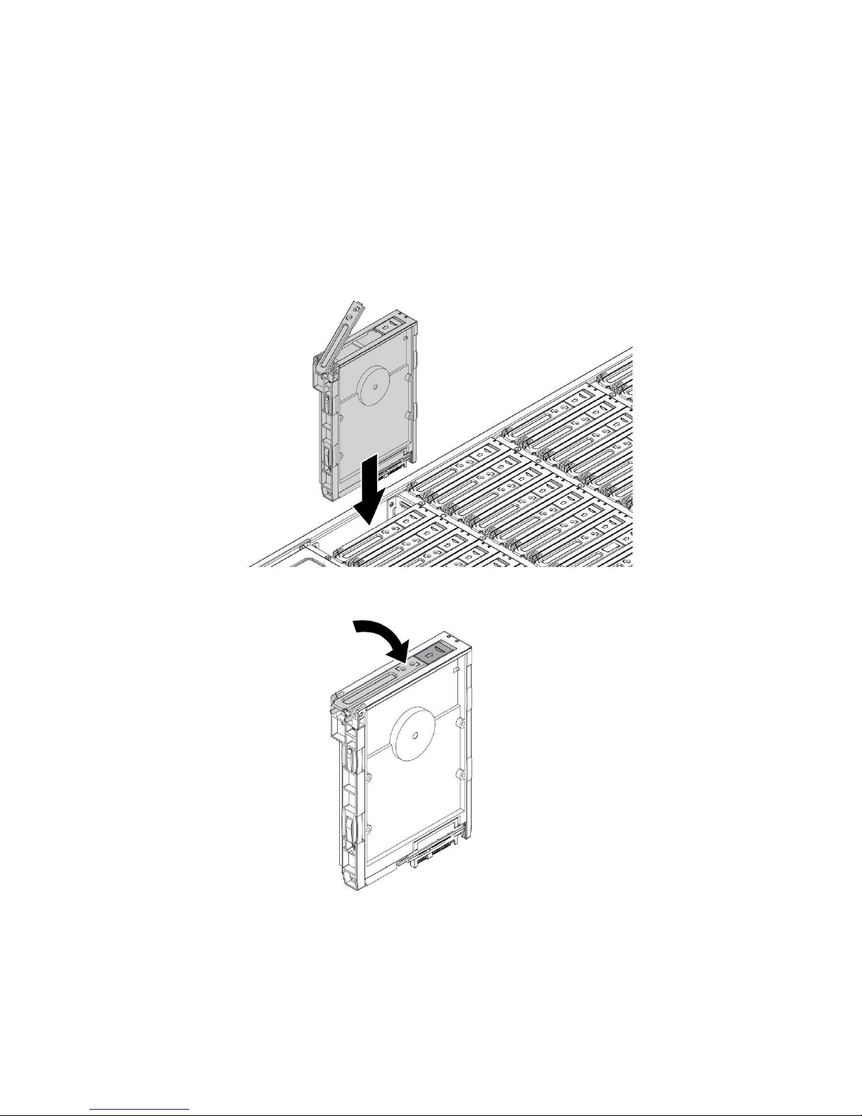
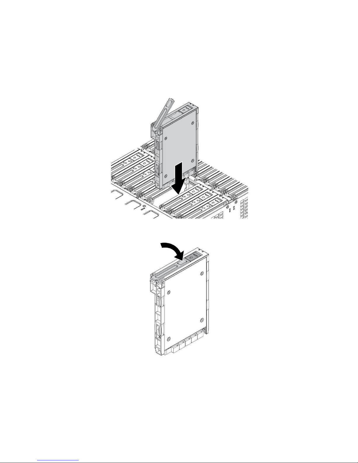
Installing the Hard Disk Drive
CAUTION!
Before powering on the server, check that each HDD is
installed and ensure empty slots contain an HDD carrier.
1. Align the HDD module with the connector on the HDD
backplane.
2. Install the HDD module.
3. Gently press down on both ends of the HDD to ensure it
is seated in the HDD backplane.
4. Push the HDD tray handle closed.
Verify that the drive is fully seated.
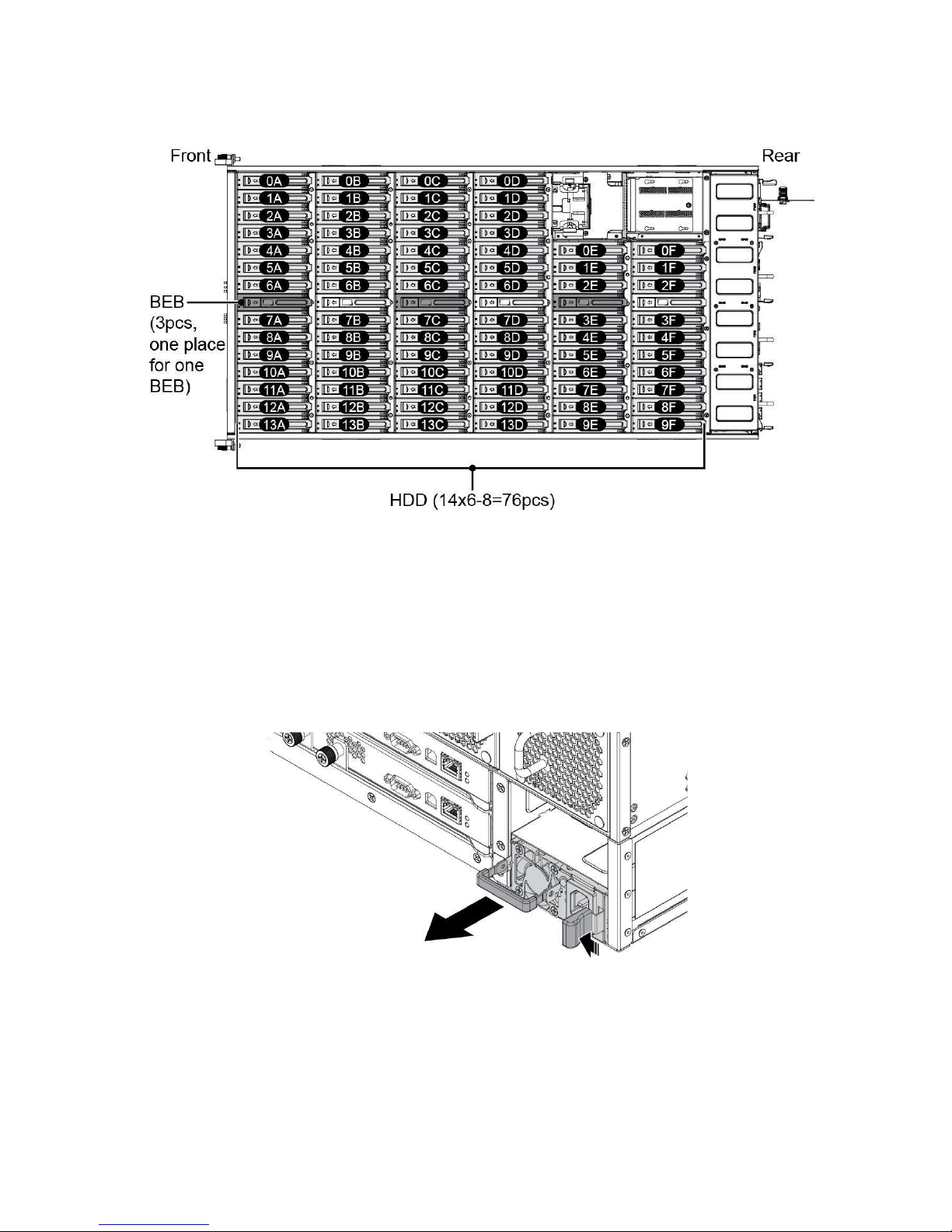
14
HDD matrix
Power supply units
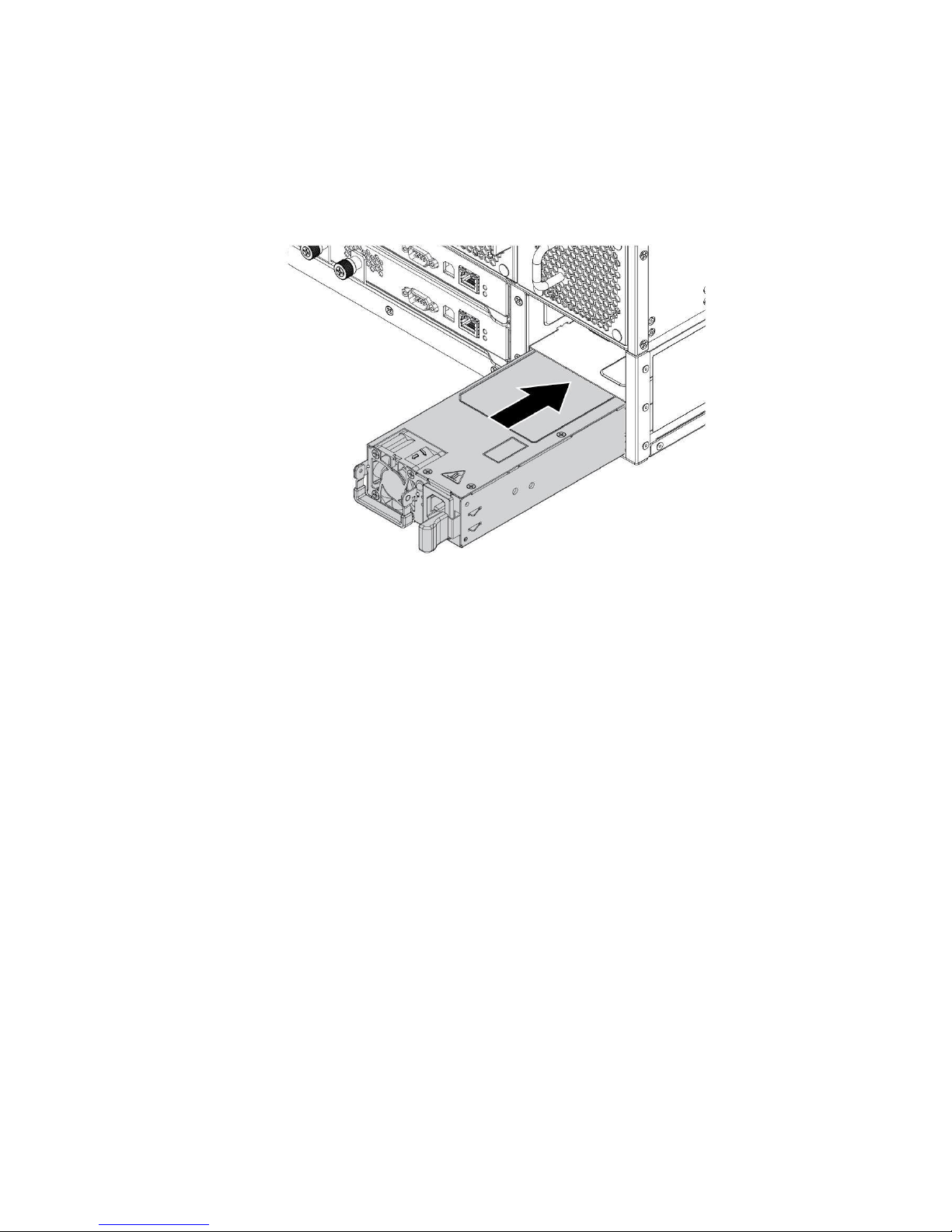
Removing the power supply unit
Please follow these steps to remove the power supply unit.
1. Lift up the handle and hold it.
2. Press the release latch to unlock the PSU.
3. Pull the PSU out to remove.
15
Installing the Redundant Power Supply Unit
Follow these steps to install the power supply unit.
1. Align the PSU in the chassis and make sure the release lever
is positioned on the right side.
2. Slide the PSU into the chassis until the release
latch is secure and the component is locked in
place.
16
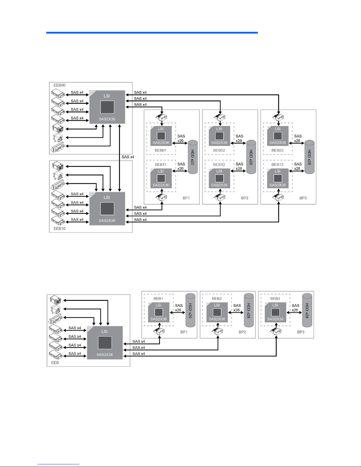
System Architecture
Storage Carrier SAS dual path
Storage Carrier SATA single path
17
Backplane Expander Board (BEB)
Removing a Backplane Expander Board (BEB)
Follow these steps to remove a Backplane Expander Board (BEB):
1. Press and slide the release button. The latch pops up.
2. Lift up the BEB tray handle to open.
3. Remove the BEB module from the chassis.
NOTE: Refer to page 17 to differentiate SAS dual path and SATA
single path.
18
Installing a Backplane Expander Board (BEB)
Follow these steps to install a Backplane Expander Board (BEB):
1. Align the BEB with the connector on the HDD backplane.
2. Install the BEB on the HDD backplane.
3. Gently press down on both ends of the BEB to ensure it is seated in the
HDD backplane.
4. Push the BEB tray handle closed.
19
Front Control Module
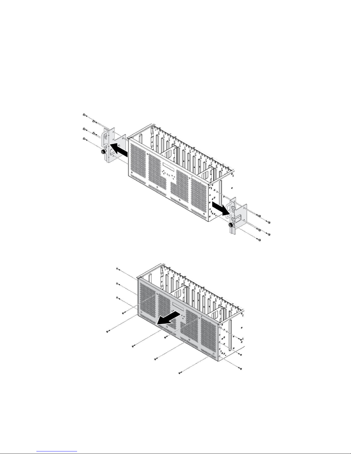
Removing the Front Control Module
Follow these steps to remove the front control module:
1. Power down the system by disconnecting the power cables.
2. Remove the securing screws and remove the mounting ears.
3. Remove the securing screws and remove the rear bracket.
20
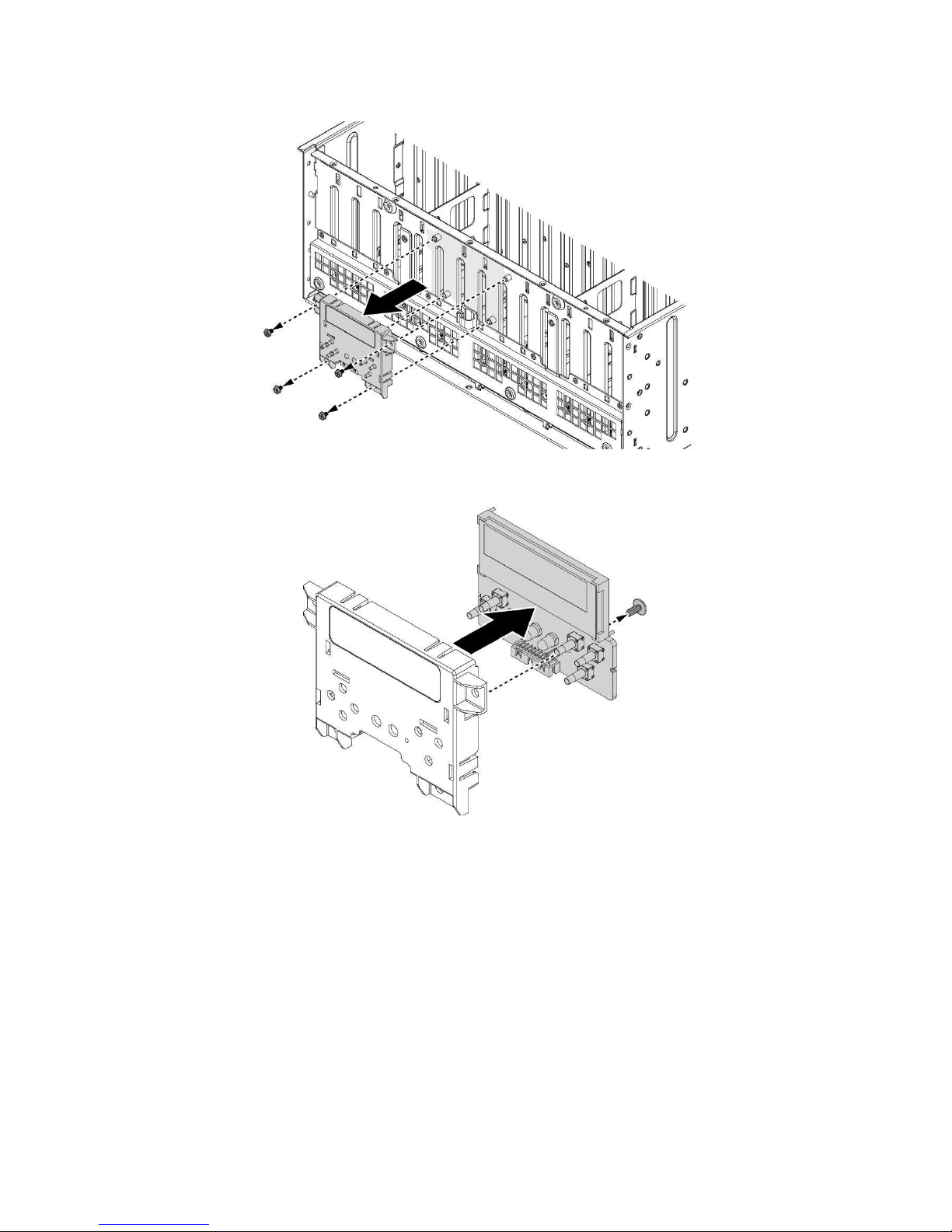
4. Remove the securing screws to remove the front control module assembly.
5. Remove the securing screw to remove the front control module.
21
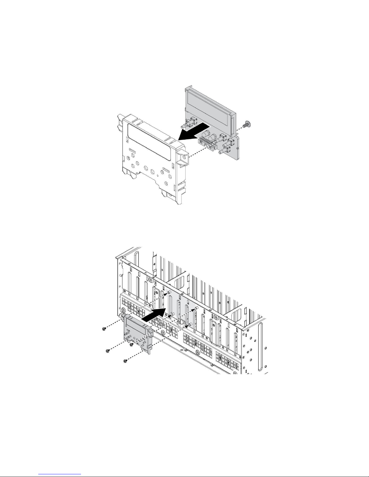
Installing the Front Control Module
Follow these steps to replace the front control module:
1. Align the front control panel with the cover.
2. Install the front control panel and secure with a screw.
3. Align the front control panel assembly on the chassis as illustrated
in the following image.
4. Install the front control panel assembly.
5. Secure the front control panel assembly to the chassis with screws.
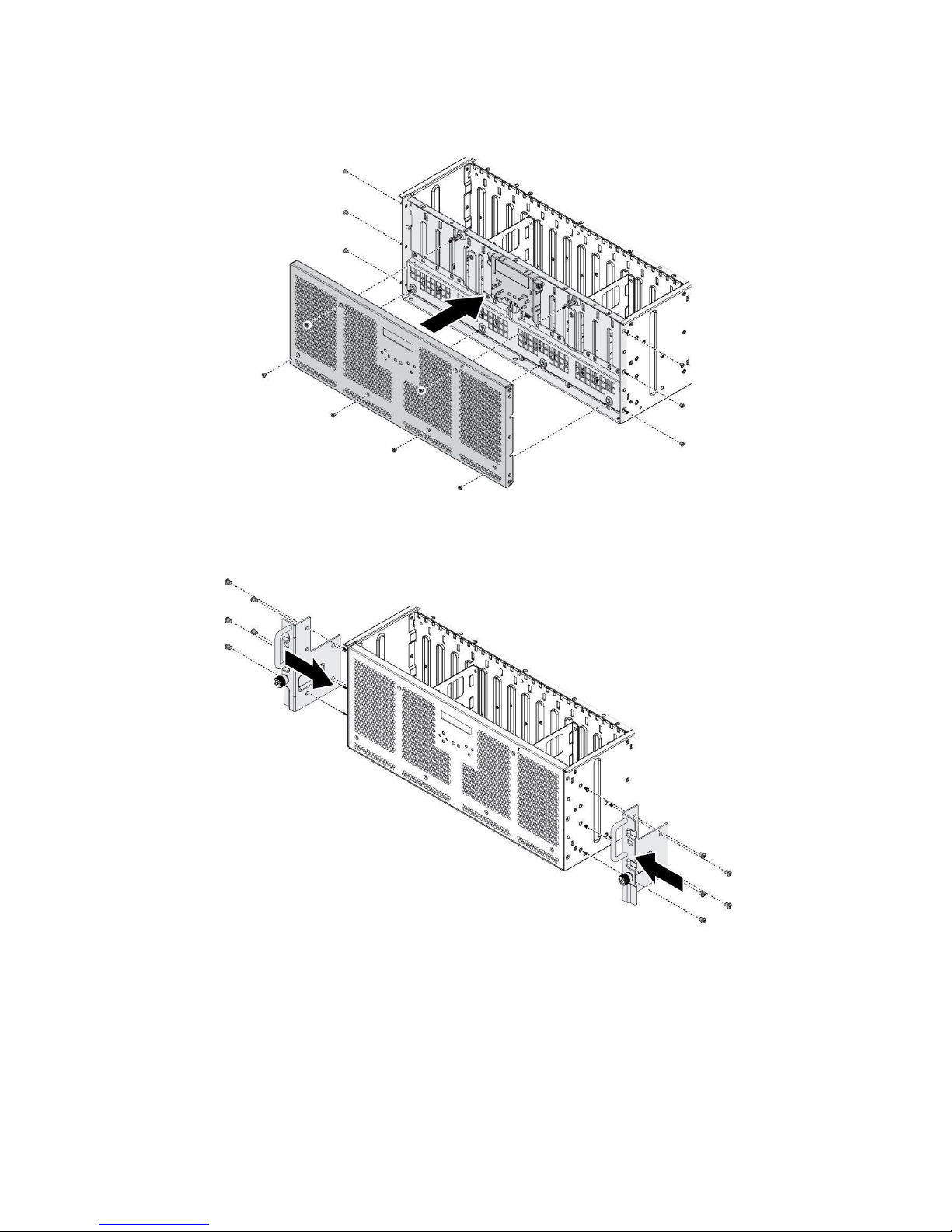
22
6. Align the front bracket on the chassis.
7. Secure the front bracket to the chassis with the
screws.
8. Secure the mounting ears to the chassis with the
screws.
23
External Expander Board (EEB)
The system supports two External Expander Boards (EEB). For purposes
of this demonstration EEB is used.
Supported External Expander Boards
Carrier JBOD SAS Dual Path
Carrier JBOD SATA Single Path
Refer to the following examples to connect single path SATA drive cables.
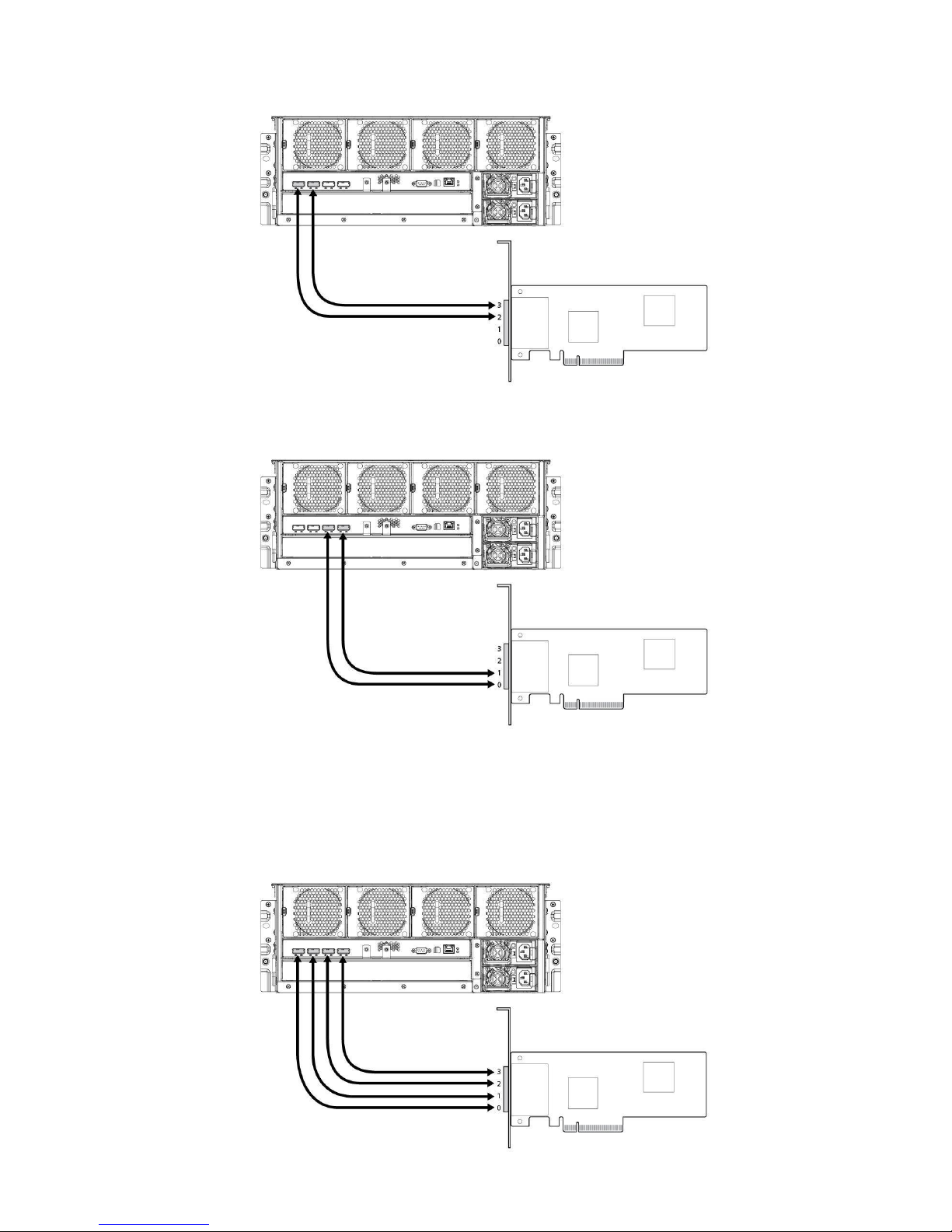
24
Correct SATA drive connection 1:
Correct SATA drive connection 2:
Incorrect SATA drive connection 1:
25
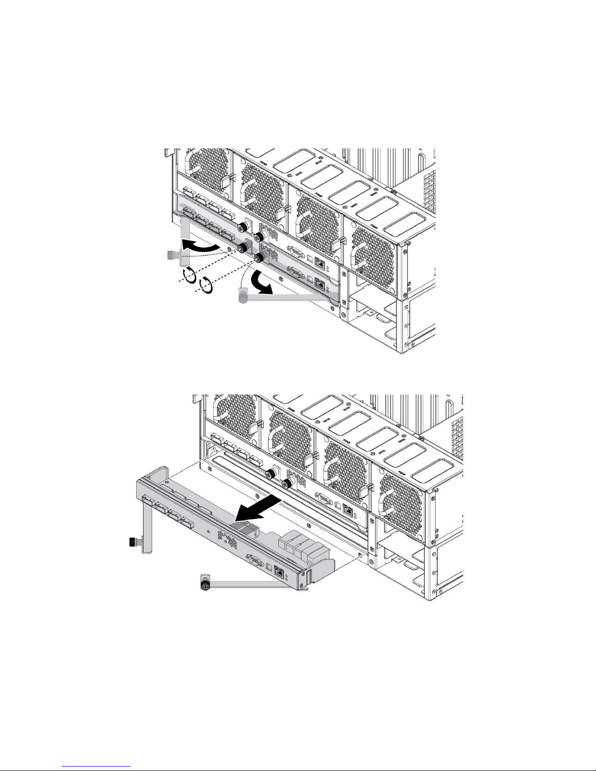
Removing the External Expander Board (EEB)
Follow these steps to remove the External Expander Board (EEB):
1. Loosen the thumb screws to unlock the EEB.
2. Pull the thumb screws to open the latches.
3. Using the latches, pull the expander out to remove.

26
4. Remove the screws.
5. Lift the expander board from the bracket.
Installing the External Expander Board
(EEB)
Follow these steps to install the External Expander Board (EEB):
1. Align the I/O ports on the EEB with the bracket.
2. Install the EEB.
3. Secure the EEB to the bracket with screws.

27
4. Align the EEB with the bay in the chassis and slide in.
5. Press the EEB in to seat correctly in place.
6. Close the latches and tighten the thumb screws to secure.

28
Fans
Removing the System Fan
Use the following steps to remove the system fan:
1. Press the release latch and pull the fan out of the fan/expander bracket.
Installing the System Fan
Use the following steps to install the system fan:
1. Align the fan assembly in the fan/expander bracket making sure the release lever is
positioned on the right side.
2. Slide the fan into the fan/expander bracket until the release latch is secured and the fan
is locked in place.

29
Removing the System Fan (for PSU Cooling)
Use the following steps to remove the system fan:
1. Press the locking lever in to unlock the system fan.
2. Remove the system fan from the chassis.
Installing the System Fan (for PSU Cooling)
Use the following steps to install the system fan:
1. Align the fan with the connector on the HDD backplane.
2. Install the system fan into the chassis.
3. Firmly press down on the system fan to activate the locking lever.

30
Power Distribution Board (PDB)
Removing the Power Distribution Board (PDB)
Follow these steps to remove the Power Distribution Board (PDB):
1. Power down the system by disconnecting the power cables.
2. Remove the screw from PDB2.
3. Slide PDB2 away from PDB1 and pull off to remove.

31
4. Loosen the thumb screw on
PDB1.
5. Lift the PDB1 up and out to
remove.

32
Installing the Power Distribution Board
(PDB)
Follow these steps to replace the Power Distribution Board (PDB):
1. Align the PDB1 with the PSU cage.
2. Slide the PDB1 over the PSU cage and install.
NOTE: PDB1 connectors are facing the inside of the PSU cage.
3. Tighten the thumb screw to secure.

33
4. Align the PDB2 over the standoffs on the PSU cage making sure the power
connectors are facing up.
5. Slide PDB2 into PDB1 to connect.
6. Secure the PDB2 to the PSU cage with a screw.

34
Mid-plane
Removing the Mid-plane
Use the following steps to remove the mid-plane:
1. Power down the system by disconnecting the power cables.
2. Remove the EEBs and system fans.
3. Remove the securing screws from the fan/expander bracket.
4. Remove the fan/expander bracket.
5. Remove the securing screws from the mid-plane.
6. Remove the mid-plane.

35
Installing the Mid-plane
Use the following steps to install the mid-plane:
1. Orient the mid-plane so that the connectors are facing the top of the
fan/expander bracket. See the following illustration.
2. Install the mid-plane. Make sure all screw holes are aligned with the bracket.
3. Install the mid-plane assembly in the chassis.
4. Secure the mid-plane assembly to the chassis with screws.
5. Install the system fans and EEBs.

36
Power Interface Board (PIB)
Removing the Power Interface Board (PIB):
Use the following steps to remove the Power Interface Board (PIB):
1. Power down the system by disconnecting the power cables.
2. Remove all the hot-swappable hard disk drive assemblies.
3. Remove all components from the system.
4. Flip the chassis and remove the securing screws.
5. Remove the PIB from the HDD backplane 3.
Installing the Power Interface Board (PIB):
Use the following steps to install the Power Interface Board (PIB):
1. Connectl the PIB to the HDD backplane 3.
NOTE: PIB connectors are facing the inside of the chassis.
2. Secure the PIB to the HDD backplane 3.

37
HDD Backplane
Removing the HDD Backplane
Use the following steps to remove the HDD Backplane:
1. Power down the system by disconnecting the power cables.
2. Remove all the hot-swappable hard disk drive assemblies.
3. Remove all components from the system.
4. Remove the securing screws.
5. Remove the HDD backplanes.

38
Installing the HDD Backplane
Use the following steps to install the HDD Backplane:
1. Align each HDD backplane in the chassis. Make sure the connectors are facing up, see
the following illustration.
2. Secure with screws.
3. Install all components.
4. Install the hot-swap hard drives.
5. Connect the power cabling and power on the system.

39
Rail
Installing the Slide Rail
Follow these steps to install the slide rail:
1. Release and detach the inner member from the slide.
2. Attach inner member to the system.

40
3. Install the nuts on the rack. See the following illustration for the
specific nut type.
A. CAGE-NUT: Support for square hole posts.
B. U-NUT: Support for round hole posts.
4. Attach outer member to the rack.
5. Pull the intermediate member outward fully from the outer member. (A)
Ensure ball bearing retainer is locked forward on the intermediate member.
(B) Horizontally install system half way into slide rail. (C)

41
6. Slide release tab and push system into rack.
7. Insert the extension bracket to the outer
member.

42
8. Fasten the chassis by shipping screw. Use screw driver to install M5x13
screw.
(A)
Install the transportation accessory (B):
A. Fasten the manual screw to lock the outer member extension bracket.
B. Fasten the shipping brackets and the M5x13 shipping screws.
Remove the transportation accessory after the system arrives the
final destination. (C)
Removing the CMA (Cable Management Arm)
Follow these steps to remove the CMA:
1. Press the "PUSH" button on the CMA plug-in part to draw it out.

43
2. Turn CMA 90 degree to the right hand side to maintain the chassis or resume
the removal.
3. Press the "PUSH" button on the CMA plug-in part to draw it out.
4. Press the "PUSH" button on the CMA plug-in part to draw it out.

44
Installing the CMA (Cable Management Arm)
Follow these steps to install the CMA:
1. Install the CMA connector to the inner member. Install CMA connector (A)
onto CMA connector base on inner member (B).
2. Install the CMA connector to the outer member. Install CMA connector (C)
onto CMA connector base on outer member (D).
3. Install the CMA connector beside the center CMA body (E) to the outer member
CMA connector base (F).

45
Switch Left/Right Side
1. Press "PUSH" button.
2. Spin 180 degree to change the direction.
Loop strap must be tied to the CMA crossbar. This is a
transportation accessory; remove the Loop strap after the system
arrives the final destination.
CAUTION

46
LCM
LCM Overview
This section includes information about the Liquid Crystal Module (LCM) display and
the features available through the menu set.
No.
Button
Description
1. LCD screen
The LCD screen offers four display states:
Home, Information, Setting and Events.
2. Left button
3. Up button
4. Right button
Press to display information pages.
5. Down button
6. Del button
If HDD backplane is off, press 0.5 seconds to power on
the
7. Power button
HDD backplane.
If HDD backplane is on; press 5 seconds to power off the
HDD backplane.
8. Set button
Press to display information pages.
Panel Lock
The Panel Lock and Unlock function is only available through CLI. You can use the
commands panel lock or panel unlock to initiate a function.

47
Home Page
The Home page is the default state of the LCD panel and displays the product name,
time and date.
Information Page
The Information pages displays information for available settings. In the Home page,
press any button to view the Information pages.
Button Function
Button
Description
Up / Down
Go through the displayed information.
Left / Right
Go to previous or next information page.
Del
No function.
Set
Enter corresponding setting page.
Information Pages
The following is a list of the available pages found in the Information menu setting.
Page
Description
TIME&DATE
Display JBOD time and date. (Time: hh:mm; Date: yyyy/mm/dd)
Use command time to validate the displayed information.
Display JBOD IP address, subnet mask, gateway and DHCP
IP CONFIG
setting.
Use command ip to validate the displayed information.
ZONE TYPE
Display JBOD current zone type and detail information.
Use command zone to validate the displayed information.
TEMP.
Display JBOD temperature sensors information.
Use command temp to validate the displayed information.
VOLTAGE
Display JBOD voltage sensors information.
Use command volt to validate the displayed information.
FAIL DISK
List JBOD failed disks.
Use command diskinfo to validate the displayed information.
FAN RPM
Display JBOD fan module information.
Use command fan to validate the displayed information.

48
FAIL LIST
List JBOD failed devices.
Use command jbodstat to validate the displayed information.
SUB-ENCL.
Display JBOD sub-enclosure mode.
Use command subenclosure to validate the displayed
information.
JBOD ID
Display JBOD ID.
Use command jbodid to validate the displayed information.
FW VER.
Display JBOD firmware version.
Use command fwinfo to validate the displayed information.
FAIL LIST
Event
Description
FAN_FAIL
Read RPM through I2C failed.
FAN_SPEED_ABNORMAL
Fan speed abnormal.
TEMP_FAIL
Read temperature through I2C failed.
TEMP_WARNING
Temperature is higher than warning temperature.
TEMP_CRITICAL
Temperature is higher than critical temperature.
VOLTAGE_FAIL
Read voltage through I2C.
VOLTAGE_WARNING
Voltage is higher than warning voltage.
VOLTAGE_CRITICAL
Voltage is higher than critical voltage.
RTC_FAIL
Read RTC through I2C.
FW_FAIL
Firmware failed.
PS_FAIL
Read power supply information through I2C.
PS_AC_FAIL
Power supply AC abnormal.
DISK_FAULT
Disk failed.
DISK_TEMP_WARNING
Disk temperature is higher than warning temperature.
DISK_TEMP_CRITICAL
Disk temperature is higher than critical temperature.
Setting Page
In an Information page, press Set to enter the corresponding setting page—only
available for TIME&DATE, IP CONFIG, ZONE TYPE, SUB-ENCL. and JBOD ID.
Button Function

49
Button
Description
Up / Down
Select value.
Left / Right
Move cursor.
Del
Exit without saving.
Set
Select the displayed menu setting.
Event Page
Three types of event displays are available; see the following for a short
description.
Interactive message: A pop-up menu that displays “Message[Y] + Event details”
Setting: A pop-up menu that displays “Event[Y/N] + Event details”
Non-interactive message: A pop-up menu that displays “Event details”. This Event page
cannot be closed.
Button Function
Button
Description
Up / Down
Go through the displayed information.
Left / Right
Move cursor.

50
Button
Del
Set
Description
Exit Event page (In a non-interactive message, the
function is not available).
No function

No.
Command
Description
Advanced
Standard
1 addr
Display all expander addresses
● ● 2 dhcp
Enable or disable DHCP function
● 3 disable
Disable specific disk, or port
● ● 4
disk
Display all disks information
● ● 5
diskcnt
Display disks error counter
● ● Information
6
enable
Enable specific disk, or port
● ●
7 fan
Get fan module status
● ● 8
fdl
Download file to specify flash
region.
● ● 9 fwfdl
Download firmware to all expanders
●
10
fwinfo
Display all expanders firmware
● ● Information
11
fwsync
Sync firmware with HA Master.
● 12
ha Display HA status and information
●
13
ident
Identify device with LED
● ●
14
ip Configure IP address
●
15
jbodid
Configure JBOD ID
● ●
CLI Commands
Overview
The firmware provides sample CLI command for user upgrading firmware and diagnostic
system status. The base implementation of the CLI supports the following command set.
The following section has complete information about every CLI command.
51

16
jbodstat
Display JBOD information.
● ● 17
log
Display or clear the system log.
4096
512
18
panel
Front LCD panel configuration
●
lock/unlock
19
passwd
Change Login password
● ● 20
phy
Display all PHYs information
● ● 21
phycnt
Display PHYs error counter
● ● Information
22
port
Display all ports information
● ●
No.
Command
Description
Advanced
Standard
23
portcnt
Display ports error counter
● ● Information
24
post
Display POST test information
● ● 25
power
Manage backplane power supply
● ◎ 26
ps Set/get power supply status
● ● 27
reset
Reset all expanders or specify
● ● expander.
28
smart
Display S.M.A.R.T info.
●
29
subenclosure
Enable or disable subenclosure
●
30
temp
Display temperature sensor
● ● Information
31
time
Set/get the system time
● ● 32
volt
Display voltage sensor
information
● ● 33
zone
Specify the zone configuration.
● ●
34
ful
File Upload from Flash
● ●
52

35
sasaddr
Display expander SAS address
● ● 36
exit
Exit CLI and telnet session
● ● 37
rev
Display board‟s revision
information
● ● 38
help
Display all CLI commands
● ●
◎ Support partial function.
CLI Commands
addr
Syntax
addr
Parameters
None.
Description
The addr command used to display all expander SAS addresses in the same enclosure.
Examples
EEB00 >addr
Enclosure Expander SAS Addresses -
0. EEB00: 50060000 000272BF
BEB01: 50060001 000272BF
BEB02: 50060002 000272BF
BEB03: 50060003 000272BF
EEB10: 50060004 000272BF
BEB11: 50060005 000272BF
BEB12: 50060006 000272BF
BEB13: 50060007 000272BF
dhcp
Syntax
dhcp enable dhcp
disable
Parameters
None.
Description
53

The dhcp command used to enable or disable DHCP function.
Examples
EEB00 >dhcp disable
DHCP function enable/disable -
DHCP function is disabled.
disable
Syntax
disable Device Name(S) FRU-ID(D)
Parameters
Device Name: „port‟ or „disk‟.
FRU-ID: ID of the port or disk. Use „all‟ parameter to disable all ports or disks.
Description
The disable command used to disable specific PHYs on disk or port.
Examples
EEB00 >disable port 0
EEB00 >disable disk 13
disk
Syntax
disk Option(S)
Parameters
Option: Function name for the disk command. All supported function names are listed below.
info: List all disk informationtemp: Show all disks temperature. The unit is Celsius.
speed: Show all disks PHY link speed. (1.5G, 3.0G, or 6.0G)
type: Show the disk interface type is SATA or SAS.
zone: Show the disk zone number.
ident: Show if disk is in identify status.
fault: Show if disk is in fault status.
hotspare: Show if disk is in hot-spare status.
conschk: Show if disk is in consistency check status.
ok: Show if disk is in OK status.
rebuild: Show if disk is in rebuild status.
54

rrabort: Show if disk is in rebuild array abort status.
remove: Show if disk is in remove status.
incrit: Show if disk is in critical array status.
Infail: Show if disk is in fail array status.
Description
The disk command used to get disk information.
Examples
EEB00 >disk info
EEB00 >disk temp
EEB00 >disk fault
diskcnt
Syntax
diskcnt
Parameters
None.
Description
The diskcnt command display all disk error counters.
Examples
EEB00 >diskcnt
enable
Syntax
enable Device Name(S) FRU-ID(D)
Parameters
Device Name: port or disk.
FRU-ID: ID of the port or disk. Use „all‟ parameter to disable all ports or disks.
Description
The enable command used to enable specific PHYs on disk or port
Examples
EEB00 >enable port 2
EEB00 >enable disk 37
55

fan
Syntax
fan
Parameters
None.
Description
The fan command used to display Fan module information.
Examples
EEB00 >fan
Enclosure FAN module management FAN01: 4420 RPM ( 15%) (OK)
FAN02: 4350 RPM ( 15%) (OK)
FAN03: 3110 RPM ( 15%) (OK)
FAN04: 3130 RPM ( 15%) (OK)
FAN05: 3790 RPM 4050 RPM ( 15%) (OK)
Auto Fan enabled
fdl
Syntax
fdl Buffer-ID(H) Buffer-Offset(H) Erase Flag(S) Expander-ID(D)
Parameters
Buffer-ID: ID of the Read/Write buffer from which the file will be downloaded.
Buffer-Offset: Starting buffer offset within the specified buffer ID to which the file
will be downloaded.
Erase Flag: y or n to specify whether to erase the buffer before downloading the file.
The default erase flag is y.
Expander-ID: Expander ID 0-7. Specify the ID to identify which expander board in JBOD
Enclosure.
Description
The fdl command downloads a file to the specified Read/Write buffer ID at the specified
buffer offset. This command uses the XMODEM protocol to transfer the file. The Erase
option allows the buffer to be erased before the file is downloaded. Erasing is enabled
by default. To abort the fdl command before starting the XMODEM protocol, press Q or
q.
Examples
EEB00 >fdl 2 0 y
56

Download File -
Please Use XModem Protocol for File Transmission.
Prepare to download, please wait a moment...
Use Q Or q to quit Download before starting XModem.
Received 492672Bytes
Buffer Download Complete
fwfdl
Syntax
fwfdl Option(S)
Parameters
Option: Specify which expander boards will be downloaded by firmware file. If the
parameter is empty, only download to self side expander boards.
all: Whole expander boards of JBOD Enclosure.
peer: Whole expander boards in opposite side of JBOD Enclosure.
Description
The fwfdl command downloads a firmware file to the specified expander boards of JBOD
Enclosure.
Examples
EEB00 >fwfdl
Download Expander Firmware -
Please Use XModem Protocol for File Transmission.
Prepare to download, please wait a moment...
Use Q Or q to quit Download before starting XModem.
Received 496640Bytes
Buffer Download Complete
Updating EEB00 Firmware ... OK
Updating BEB01 Firmware ... OK
Updating BEB02 Firmware ... OK
Updating BEB03 Firmware ... OK
fwinfo
Syntax
fwinfo
Parameters
None.
57

Description
The fwinfo command is used to display firmware versions for all expander boards in JBOD
Enclosure.
Examples
EEB10 >fwinfo
fwsync
Syntax
fwsync Board-SRC-ID(D) Board-DEST-ID(D)
Parameters
Board-SRC-ID: Specify which expander board to be source firmware. Support only one
expander ID.
Board-DEST-ID: Specify which expander boards to be downloaded. Support one or more
expander IDs.
Description
The fwsync command is used to synchronize firmware with Master. If no any parameters,
the firmware in other expander boards which are not same as HA Master will be downloaded
and synchronized as HA Master automatically.
Examples
EEB00 >fwsync
Master (EEB00) firmware: 0023/0023 (Active/Backup)
Press 'y' to sync firmware for all expanders.
Updating BEB01 Firmware ... ######################################### OK (reset)
Updating BEB02 Firmware ... ######################################### OK (reset)
Updating BEB03 Firmware ... ######################################### OK (reset)
Updating BEB11 Firmware ... ######################################### OK (reset)
Updating BEB12 Firmware ... ######################################### OK (reset)
Updating BEB13 Firmware ... ######################################### OK (reset)
Updating EEB10 Firmware ... ######################################### OK (reset)
ha
Syntax
ha Option(S)
Parameters
Option: Run High Available (HA) functionality with assigned option.
status: Display HA status and information. (default)
loop: Display HA status and information every one second.
58

HA
Status and
Information
-
[HW:ADV]
ID
Name Role
FW ZT SEID
EID
PL
RG
VDP
PHYs COMMTO
*0
EEB00
M
0023
FF
4C
FF FF 00~00(78) 50~BF(76)
On 1 BEB01
0023
FF
4C
FF
00~00(78) 50~BF(76)
On 2 BEB02
0023
FF
4C
FF
00~00(78) 50~BF(76)
On 3 BEB03
0023
FF
4C
FF
00~00(78) 50~BF(76)
On 4 EEB10
S
0023
FF
4C
FF FF 04~00(74) 50~BF(76)
On 5 BEB11
0023
FF
4C
FF
04~00(74) 50~BF(76)
On 6 BEB12
0023
FF
4C
FF
04~00(74) 50~BF(76)
On 7 BEB13
0023
FF
4C
FF
04~00(74) 50~BF(76)
On
info: Display latest HA runtime information.
enable: Enable local HA functionality.
disable: Disable local HA functionality.
state: Get enable state of HA functionality.
Description
The ha command runs operations related with High Available (HA) functionality.
Examples
EEB00 >ha
--------------------------------------------------------------------
ident
Syntax
ident Module Name(S) Stop(S)
Parameters
Module Name: The supported module names are listed below.
JBOD: jbod, JBOD.
BEB: BEB01 - BEB03, BEB05 - BEB07.
EEB: EEB00, EEB04.
Temperature: TEMP00 - TEMP12.
Voltage: VOLT00 - VOLT10.
Disk: DISK00 - DISK76.
stop: Stop identifying the UID LED on the specific module.
Description
The ident command used to identify the location of the specific module device.
Examples
EEB00 >ident jbod
59

EEB00 >ident jbod stop
EEB00 >ident BEB03
EEB00 >ident BEB03 stop
EEB00 >ident DISK55
EEB00 >ident DISK55 stop
ip
Syntax
ip IP Address(S) Sub-Mask Address(S) Gateway Address(S)
Parameters
IP Address: Specify network IP Address.
Sub-Mask Address: Specify network sub-mask address.
Gateway Address: Specify network gateway address.
Description
The ip command is used to configure the network interfaces.
Examples
EEB10 >ip 192.168.1.5 255.255.255.0 192.168.1.254
Saved IP Configuration -
DHCP Enabled. . . . . . . . . . . : No
IP Address. . . . . . . . . . . . : 192.168.1.5
Subnet Mask . . . . . . . . . . . : 255.255.255.0
Default Gateway . . . . . . . . . : 192.168.1.254
jbodid
Syntax
jbodid ID(D)
Parameters
ID: JBOD ID which will be configured into the system. The range of the ID is 0 to 9.
Description
The jbodid command used to configure JBOD ID or display the currently JBOD ID.
Examples
EEB00 >jbodid
Configure JBOD ID -
Active JBOD ID:
JBOD ID is 8.
Saved JBOD ID:
60

JBOD ID is 8.
EEB00 >jbodid 1
Configure JBOD ID -
Active JBOD ID:
JBOD ID is 8.
Saved JBOD ID:
JBOD ID is 1.
Do you want to reset for changes to take effect? (y/n)
jbodstat
Syntax
jbodstat
Parameters
None.
Description
The jbodstat command display system health status. Any system detected error will be
listed by this command. If there is no error exists in the system, the command shows
nothing.
Examples
EEB00 >jbodstat
Display JBOD Status -
JBOD Status
==========================-- - FAN module removed
EEB00
==========================-- - FAN module removed (ID:0)
log
Syntax
log show Count(D) log show Option1(S) log get Count(D) log get Option2(S) log clear
Parameters
show: Display Event Log records (default count is100) and will not clear logs displayed.
get: Display Event Log records (default count is100) and clear logs displayed.
clear: Clear whole Event Log records.
Count: 1 - 4096.
61

Option1: Function name for the command. All supported function names are listed below.
all: All event log.
count: Get total event log count.
type=string: Specify Event Log type to be filtered. Supported string are „power‟, „sas‟,
„hdd‟, „sys‟, „fw‟, „exp‟, „fan‟, „ipc‟, „vol‟, „temp‟, „rtc‟, „ha‟, and „unknow‟.
level=number: Specify Event Log level to be filtered. Supported number from 0 to 5.
hex: Display hexadecimal format of Event Log.
Option2: Description same as Option1, only support all, count, and hex.
Description
The log command is used to display and control Event Log.
Examples
EEB00 >log show count
Manage event logs -
Total log count is : 4096
EEB00 >log show 1
Manage event logs -
The count is 1.
#0001 Information 2014/03/26 15:53:06
-----------------------------------------------------------------Type : Expander
Event: Expander reset. BEB01
------------------------------------------------------------------
panel
Syntax
panel lock
panel unlock
Parameters
None.
Description
The panel command used to lock or unlock front panel. When the panel was locked, all
system information still can be display in LCD module but any system configuration can
NOT be set via front panel.
Examples
62

EEB00 >panel lock
EEB00 >panel unlock
passwd
Syntax
passwd
Parameters
None.
Description
The passwd command used to change password for system log-in.
Examples
EEB00 >passwd
Change Management Password -
OLD password: ***
NEW password: ***
CONFIRM password: ***
Password has been changed!
phy
Syntax
phy Expander-ID(D)
Parameters
Expander-ID: Specify the ID to identify which expander board in JBOD Enclosure. None
of this option means whole expander boards in JBOD Enclosure.
Description
The phy command is used to display detail information of phy in expander board.
Examples
EEB00 >phy
phycnt
Syntax
phycnt reset(S) Expander-ID(D)
Parameters
reset: Reset Phy Error counters. (optional)
63

Expander-ID: Specify the ID to identify which expander board in JBOD Enclosure. None
of this option means whole expander boards in JBOD Enclosure.
Description
This phycnt displays PHY error counters, PHY event counters and generic broadcast counter
for all Phys.
Examples
EEB00 >phycnt reset
Phys Layer Counters -
Phy counters successfully reset.
port
Syntax
port
Parameters
None.
Description
The port command is used to display detail information of port in JBOD Enclosure.
Examples
EEB00 >port
portcnt
Syntax
portcnt
Parameters
None.escription
This portcnt displays phy error counters, phy event counters and generic broadcast
counter for all ports.
Examples
EEB00 >portcnt
post
Syntax
post Expander-ID(D)
Parameters
64

Expander-ID: 0-7. If the parameter is empty, the command display all post information.
Description
The post command displays the ECC information. Instead of displaying all the contents
of the ECC information, the success/failure of the internal memory test and forced ECC
error tests and also the reason for the tests to fail are displayed. Using this command,
you can view the POST information of the following peripherals and ECC error information.
Internal Memory
External Memory
Smart Serial
Watchdog timer
Timer1
Timer2
Interrupt
Phy loopback
ISTWI Channel 0
ISTWI Channel 1
ISTWI Channel 2
ISTWI Channel SEP
Examples
EEB00 >post 2
Check POST status of Bobcat On-Chip Devices -
BEB02 POST Information:
================================================================================
On-Chip Device POST Status
================================================================================
Smart Serial :PASS
Watchdog Timer :PASS
Timer 1 :PASS
Timer 2 :PASS
Interrupt :PASS
Phy Loopback :PASS
ISTWI Channel 0 :PASS
ISTWI Channel 1 :PASS
ISTWI Channel 2 :PASS
ISTWI Channel SEP :PASS
Internal RAM Test :PASS
Forced ECC Error Test :PASS
power
65

0.
PS00:
ID
: Server Power Supply
MODEL
: PS-2112-5L3-LF
REVISION
: X1
LOCATION
: 01
DATE
: Week 10, 2013
BAR CODE
: 6XXXX01X1D1001W
FAN SPEED
: 5440 RPM
TEMPERATURE
: 43 C
VOLTAGE
: 12.9 V
Syntax
power Option(S)
Parameters
Option: Function name for the power command. All supported function names are listed
below.
on: Set on to power on Back Plane boards.
off: Set off to power off Back Plane boards.
auto: Set auto to power on Back Plane boards automatically after AC plug-in PSU
manual: Set manual to power on Back Plane boards manually after AC plug-in PSU.
lock: Set lock to lock the function of power button.
unlock: Set unlock to unlock the function of power button.
Description
The power command used to manage the power state of Back Plane boards.
Examples
EEB00 >power on
EEB00 >power off
ps
Syntax
ps
Parameters
None.
Description
The ps command used to get information about power supply modules
Examples
EEB00 >ps
Enclosure Power Supply Management -
66

CURRENT
: 19.37 A
INPUT WATT
: 250 W
OUTPUT WATT
: 234 W
1.
PS01:
ID
: Server Power Supply
MODEL
: PS-2112-5L3-LF
REVISION
: X1
LOCATION
: 01
ATE
: Week
10, 2013
BAR CODE
: 6XXXX01X1D1000S
FAN SPEED
: 5536
RPM
TEMPERATURE
: 44 C
VOLTAGE
: 12.6
V
CURRENT
: 18.50 A
INPUT WATT
: 246
W OUTPUT WATT
: 222
W
reset
Syntax
reset watchdog(S) Option(S)
Parameters
watchdog: Issue the watchdog reset. (optional)
Option: All supported function names are listed below.
all: Reset all expanders.
peer: Reset peer side expanders.
0-7: Expander ID.
Description
The reset command used to reset any expanders in JBOD. The default reset is hard or cold
reset. If you issue the reset watchdog command, the watchdog reset is triggered.
Examples
EEB00 >reset all
Reset Enclosure Expanders -
Reseting BEB13 ... OK
Reseting BEB12 ... OK
Reseting BEB11 ... OK
Reseting EEB10 ... OK
Reseting BEB03 ... OK
Reseting BEB02 ... OK
Reseting BEB01 ... OK
Reseting EEB00 ...
smart
Syntax
67

Display S.M.A.R.T InformationDISK25
Information:
Vendor
:SEAGATE
Product
:ST4000NM0023
Revision
:0003
Logical Unit ID
:0x1234567812345678
Serial Number
:Z1Z0ZB2E00009350EE9V
User Capacity
:3726
GB
Max LBA
:7814037168 blocks
Logical block size
:512 bytes
Rotation Rate
:7200
rpm
Form Factor
:3.5 inches
Current Drive Temperature
:32 C
( 89 F)
Drive Trip Temperature
:40 C
(104 F)
Manufactured Date
:in week 26 of year 2014
Cycle count over device lifetime
:10000
Accumulated start-stop cycles
:5988
Load-unload count over device lifetime
:300000
Accumulated load-unload cycles
:5994
smart Disk ID(D)
Parameters
Disk ID: 0-75. The Disk ID in system.
Description
The smart command used to get Disks S.M.A.R.T information. If the parameter is empty,
the command displays all disks information.
Examples
EEB00 >smart 25
Blocks sent to initiator = 14207 Blocks received from initiator = 17817
Blocks read from cache and sent to initiator = 265
Number of read and write commands whose size <= segment size = 16 Number of read and
write commands whose size > segment size = 0 number of hours powered up = 707 hr 15 min
number of minutes until next internal SMART test = 52
subenclosure
Syntax
subenclosure enable subenclosure disable
Parameters
None.
Description
The subenclosure command used to display currently enclosure mode and to switch between
sub-enclosure mode and enclosure mode.
68

Examples
EEB00 >subenclosure
EEB00 >subenclosure disable
temp
Syntax
temp
Parameters
None.
Description
The temp command used to display temperature sensors information.
82Examples
EEB00 >temp
Enclosure temperature sensor information TEMP00: 52 C (125 F) (OK)
TEMP01: 59 C (138 F) (OK)
TEMP02: 64 C (147 F) (High Warning)
TEMP03: 55 C (131 F) (OK)
TEMP04: 51 C (123 F) (OK)
TEMP05: 53 C (127 F) (OK)
TEMP06: 62 C (143 F) (High Warning)
TEMP07: 62 C (143 F) (High Warning)
TEMP08: 33 C ( 91 F) (OK)
TEMP09: 44 C (111 F) (OK)
TEMP10: 43 C (109 F) (OK)
TEMP11: 0 C ( 32 F) (Disconnected)
TEMP12: 30 C ( 86 F) (OK)
time
Syntax
time Year(D) Month(D) Day(D) Hour(D) Minute(D) Second(D)
Parameters
Year: Set system current time (Year 0~99).
Month: Set system current time (Month 1~12).
Day: Set system current time (Day 1~31).
Hour: Set system current time (Hour 0~23).
Minute: Set system current time (Minute 0~59)
Second: Set system current time (Minute 0~59)
69

Description
The time command used to set or get current system time
Examples
EEB00 >time
System Current Time Management -
Current SYS Time: 2014/03/24 18:39:59
EEB00 >time 14 03 24 18 45 00
volt
Syntax
volt
Parameters
None.
Description
The volt command used to display voltage sensors information.Examples
EEB00 >volt
Enclosure voltage sensor information VOLT00: 5.04 V (OK)
VOLT01: 5.04 V (OK)
VOLT02: 5.04 V (OK)
VOLT03: 5.04 V (OK)
VOLT04: 5.03 V (OK)
VOLT05: 5.03 V (OK)
VOLT06: 5.02 V (OK)
VOLT07: 5.04 V (OK)
VOLT08: 5.05 V (OK)
VOLT09: 5.04 V (OK)
VOLT10: 5.04 V (OK)
zone
Syntax
zone Zone-Type(D)
Parameters
Zone-Type: 0-2.
0: All disks in a cluster
1: Disks are divided into two clusters
2: Disks are divided into four clusters
70

Description
The zone command used to configure JBOD Zone Type. (JBOD needs to be reset for changes
to take effect).
Examples
EEB00 >zone 1
ful
Syntax
ful Buffer-ID(H) Buffer-Offset(H) Size In Bytes(D)
Parameters
Buffer-ID: ID of the Read/Write buffer from which the file will be uploaded.
Buffer-Offset: Starting buffer offset within the specified buffer ID from which the file
will be uploaded.
Size In Bytes: Size of the file, in bytes.
Description
The ful command uploads data to a file from the buffer offset within a specified Read/Write
buffer ID. This command uses XMODEM protocol for file transfer. The size of the uploaded
file is specified as a command line parameter. Due XMODEM protocol nature, the size of
uploaded data will be multiples of 128 bytes. Therefore, if the mentioned size is not
a multiple of 128 bytes, pad bytes will be added with undefined contents. Data beyond
the specified size must be ignored. To exit the ful command before starting the XMODEM
protocol, press Q or q.
Examples
EEB00 >ful 2 0 128
Upload File -
Please Use XModem Protocol to Receive File.
Use Q Or q to quit Download before starting XModem.
Transmitted 128Bytes
Buffer Upload Complete
sasaddr
Syntax
sasaddr
Parameters
None.
71

Expander SAS
Addresses -
EXP Port SAS
Address:
0x50060000000272BF
SXP
Port SAS
Address:
0x50060000000272BD
STP
Port SAS
Address:
0x000000000000003E
Description
The sasaddr command used to display expander SAS address (EXP, SXP, and STP ports).
Examples
EEB00 >sasaddr
exit
Syntax
exit
Parameters
None.
Description
The exit command used to close TCP/IP session.
Examples
EEB00 >exit
rev
Syntax
Rev
Parameters
None.
Description
The rev command used to display the following information:
Hardware revision information: Vendor ID, product ID, product revision level, component
ID, component revision level.
Revision information for the firmware images resident in Flash. It also displays which
firmware image is currently
SDK revision information
Examples
72

EEB00 >rev
help
Syntax
help Command(S)
Parameters
Command: CLI command name.
Description
The help command displays help on all the registered CLI commands, there is no argument
passed to this command. Use the help command for the required help.
Examples
EEB00 >help phy
=================================================================
Test Command
=================================================================
Display all phy info. phy [Expander-ID <0 - 7>]
=================================================================
73

Regulatory information
Class A
This equipment has been tested and found to comply with the limits for a Class
A digital device, pursuant to part 15 of the FCC Rules. These limits are designed
to provide reasonable protection against harmful interference when the equipment
is operated in a commercial environment. This equipment generates, uses, and can
radiate radio frequency energy and, if not installed and used in accordance with
the instruction manual, may cause harmful interference to radio communications.
Operation of this equipment in a residential area is likely to cause harmful
interference in which case the user will be required to correct the interference
at his own expense.
European Union regulatory notice
Products bearing the CE mark comply with one or more of the following EU directives
as may be applicable:
Low Voltage directive 2014/35/EC
EMC directive 2014/30/EU
Ecodesign directive 2009/125/EC
RoHS directive 2011/65/EU
Compliance with these directives is assessed using applicable harmonised European
standards.
The full Declaration of Conformity can be found at the following website:
http://www.tradedx.eu/ certificates.
The point of contact for regulatory matters is TradeDX s.r.o., Karlov 245, 28401
Kutná Hora, Czech Republic.
Safety
Before installing this product, read the Safety Information.
74

Warnings & Safety/
Important safety and compliance
information
Be sure to read all caution and warning statements in this documentation before
performing any procedure in this user and maintenance guide. To avoid potential
problems, ALWAYS read the warnings, cautionary and safety information that comes
with server documentation before removing, replacing, reseating or modifying
system components.
Safety precautions
Observe the following safety precautions when setting up equipment:
Follow all cautions and instructions marked on the equipment.
Ensure that the voltage and frequency of power source match the voltage and
frequency inscribed on the equipment’s electrical rating label.
Never push objects of any kind through openings in the equipment. Dangerous
voltages may be present.
Conductive foreign objects could produce a short circuit that could cause
fire, electric shock, or damage to your equipment.
Safety Instructions
1. Please read these safety instructions carefully.
2. Please keep this Manual for later reference.
3. Please disconnect this equipment from AC outlet before cleaning. Don’t use
liquid or sprayed detergent for cleaning. Use moist sheet or cloth for
cleaning.
4. For pluggable equipment, the socket-outlet must be installed near the
equipment and must be easily accessible.
5. Please keep this equipment from humidity.
6. Place this equipment on a safe reliable surface when installing. A drop or
fall could cause injury.
7. Enclosure openings are for air circulation and protect the equipment from
overheating. DO NOT COVER THE OPENINGS.
8. Make sure the voltage of the power source matches rated voltages.
9. Place the power cord so that it won't be stepped on or tripped over. Do not
place anything on top of the power cord.
10. All cautions and warnings on the equipment should be noted.
75

This symbol indicates the presence of hazardous energy circuits or
electric shock hazards. Refer all servicing to qualified personnel.
WARNING: Do not open this enclosure to reduce the risk of injury from
electric shock hazards. Refer all maintenance, upgrades and servicing
to qualified personnel.
CAUTION: There is a risk of personal injury and equipment damage. Follow
the instructions.
CAUTION: The following label indicates sharp edges, corners or joints
nearby.
CAUTION: The following label indicates a hot surface nearby.
Hot surface. Avoid contact. Surfaces are hot and may cause
personal injury if touched.
WARNING: Allow the surface to cool before touching to reduce the
risk of injury from a hot component.
CAUTION: This symbol indicates the presence of electric shock
hazards. The area contains no user or field serviceable parts. Do
not open for any reason.
WARNING: Do not open this enclosure to reduce the risk of injury
from electric shock hazards.
CAUTION: This symbol indicates hazardous moving parts are nearby.
11. If the equipment is not used for a long time, disconnect the equipment from
outlet to avoid damage to the system by transient voltages.
12. Do not spill liquids onto equipment; this may cause fire or electrical shock.
13. Never open the equipment. For safety reasons, the equipment should only be
opened by qualified service personnel.
14. If any of the following situations arises, have the equipment checked by
qualified service:
a. The power cord or plug is damaged.
b. Liquid seeped into the equipment.
c. The equipment has been exposed to moisture.
d. The equipment does not work well or operation does not match behavior
described in user's manual.
e. The equipment has been dropped or damaged.
f. The equipment has obvious signs of damage.
15. DO NOT LEAVE THIS EQUIPMENT IN AN ENVIRONMENT WHERE TEMPERATURES EXCEED 70
°C (158 °F); IT MAY DAMAGE THE EQUIPMENT.
Symbols
The following symbols may be placed on the equipment to indicate the presence
of potential hazardous condition.
76

CAUTION: When replacing the lithium battery, use only the TradeDX spare
battery designated for this product. If your system has a module
containing a lithium battery, replace it only with the same module type
made by the same manufacturer. The battery contains lithium and can
explode if not properly used, handled, or disposed of.
Do not:
Throw or immerse into water
Heat to more than 100°C (212°F)
Repair or disassemble
Dispose of the battery as required by local ordinances or regulations.
CAUTION: When laser products (such as CD-ROMs, DVD drives, fiber optic
devices, or transmitters) are installed, note the following:
Do not remove the covers. Removing the covers of the laser product could result
in exposure to hazardous laser radiation. There are no serviceable parts inside
the device.
Use of controls or adjustments or performance of procedures other than those
specified herein might result in hazardous radiation exposure.
Some laser products contain an embedded Class 3A or Class 3B laser diode.
Note the following.
Laser radiation when open. Do not stare into the beam, do not view directly
with optical instruments, and avoid direct exposure to the beam.
Class 1 Laser Product
CAUTION: Do not place any object on top of rack-mounted devices.
CAUTION:
Laser Drive Equipment
The optical transceiver module in this server is a laser Class 1 product.
Ambient Operation
This equipment cannot be operated above an ambient operation temperature
of 40 degrees centigrade.
Equipment Location
This equipment can only be accessed by SERVICE PERSONNEL or by USERS who
have been instructed about the reasons for the restrictions applied to
the location. Access is through the use of a TOOL or lock and key, or
other means of security, and is controlled by the authority responsible
for the location.
Safety statements
READ THIS IMPORTANT SAFETY INFORMATION SECTION. RETURN TO THIS MANUAL FOR
REFERENCE. READ THIS SECTION BEFORE SERVICING.
77

CAUTION: Do not connect the server to any other type of power
system to reduce the risk of electric shock.
WARNING: This server is suitable for use on an IT power
distribution system whose maximum phase-to-phase voltage is 240
V under any distribution fault condition.
Electrical current from power, telephone, and communication cables
is hazardous. To avoid a shock hazard:
Do not connect or disconnect any cables or perform installation,
maintenance, or reconfiguration of this product during an electrical
storm.
Connect all power cords to a properly wired and grounded electrical
outlet.
Connect to properly wired outlets any equipment that will be attached
to this product.
When possible, use one hand only to connect or disconnect signal cables.
Never turn on any equipment when there is evidence of fire, water, or
structural damage.
Disconnect the attached power cords, telecommunications systems,
networks, and modems before you open the device covers, unless
instructed otherwise in the installation and configuration procedures.
Connect and disconnect cables as described in the following table when
installing, moving, or opening covers on this product or attached
devices.
To Connect:
To Disconnect:
1 Turn everything OFF.
2 First, attach all cables to
devices.
3 Attach signal cables to
connectors.
4 Attach power cords to outlet.
5 Turn device ON.
1 Turn everything OFF.
2 First, remove power cords
from outlet.
3 Remove signal cables from
connectors.
4 Remove all cables from
devices.
CAUTION: The power control button on the device and the power
switch on the power supply do not turn off the electrical current
supplied to the device. The device also might have more than one
power cord. To remove all electrical current from the device,
ensure that all power cords are disconnected from the power source.
CAUTION: Never remove the cover on a power supply or any part that
has the following label attached.
Hazardous voltage, current, and energy levels are present inside
any component that has this label attached. There are no
serviceable parts inside these components. If you suspect a problem
with one of these parts, contact a service technician.
Overloading a branch circuit is potentially a fire hazard and a
shock hazard under certain conditions. To avoid these hazards,
ensure that your system electrical requirements do not exceed
branch circuit protection requirements. Refer to the information
that is provided with your device for electrical specifications.
78

WARNING: Only authorized trained technicians should attempt to repair
this equipment. All troubleshooting and repair procedures are detailed
to allow only subassembly/module-level repair. Because of the complexity
of the individual boards and subassemblies, no one should attempt to make
repairs at the component level or to make modifications to any printed
wiring board. Improper repairs can create a safety hazard.
WARNING: To reduce the risk of personal injury or damage to the
equipment, be sure that:
The leveling feet are extended to the floor.
The full weight of the rack rests on the leveling feet.
The stabilizing feet are attached to the rack if it is a single-rack
installation.
The racks are coupled together in multiple-rack installations.
Only one component is extended at a time. A rack may become unstable
if more than one component is extended for any reason.
WARNING: To reduce the risk of electric shock or damage to the equipment:
Do not disable the power cord grounding plug. The grounding plug is
an important safety feature.
Plug the power cord into a grounded (earthed) electrical outlet that
is easily accessible at all times.
Unplug the power cord from the power supply to disconnect power to the
equipment.
Do not route the power cord where it can be walked on or pinched by
items placed against it. Pat particular attention to the plug,
electrical outlet and the point where the cord extends from the server.
WARNING: To reduce the risk of personal injury or damage to the
equipment:
Observe local occupation health and safety requirements and guidelines
for manual handling.
Obtain adequate assistance to lift and stabilize the chassis during
installation or removal.
The server is unstable when not fastened to the rails.
When mounting the server in a rack, remove the power supplies and any
other removable module to reduce overall weight of the product.
CAUTION: To properly ventilate the system, at least 7.6cm (3.0 in) of
clearance at the front and back of the server should be provided.
CAUTION: The server is designed to be electrically grounded (earthed).
Only plug the AC power cord into a properly grounded AC outlet to ensure
power operation.
Warnings and cautions
79

WARNING: The circuit boards and hard drives contain electronic
components that are extremely sensitive to static electricity. Ordinary
amounts of static electricity from clothing or the work environment can
destroy these components. Wear an antistatic wrist strap when handling
the media drive assemblies, circuit boards, processors, DIMMs and PCIe
cards. When servicing or removing server components, attach an antistatic
strap to your wrist and then to a metal area on the server chassis then
disconnect the power cord from the server and the wall receptacle.
Following this caution equalizes all electrical potentials within the
server.
Electrostatic discharge
Preventing electrostatic discharge
To prevent damaging the system, be aware of the precautions to follow when setting
up the system or handling parts. A discharge of static electricity from a finger
or other conducer may damage system boards or other static-sensitive devices.
This type of damage may reduce the life expectancy of the device.
To prevent electrostatic damage:
Avoid hand contact by transporting and storing products in static-safe
container.
Keep electrostatic-sensitive parts in their container until they arrive at
static-free workstations.
Place parts on a grounded surface before removing from their containers.
Avoid touching pins, leads or circuitry.
Always be properly grounded when touching a static-sensitive component or
assembly.
Grounding methods to prevent electrostatic discharge
Use one or more of the following methods when handling or installing
electrostatic-sensitive parts:
Use a wrist strap connected by a ground cord to a grounded workstation or
computer chassis. Wrist straps are flexible straps with a minimum of 1
mega-ohm +/-10 percent resistance in the ground cords. Wear the strap snug
against the skin to provide proper ground.
Use heel straps, toe straps or boot straps at standing workstations. Wear
the straps on both feet when standing on conductive floors or dissipating
floor mats.
Use conductive field service tools.
Use a portable field service kit with a folding static-dissipating work mat.
Have an authorized reseller install the part if any of suggested equipment for
proper grounding is not available.
Contact an authorized reseller for more information on static electricity or
assistance with product installation.
80

Specification
Value
Temperature
range*
—
Operating
5~35 degree of Celsius
Non-operating
-40~70 degree of Celsius
Relative humidity
(noncondensing)
50%~80%
Non-operating
50%~90% (Non-condensing)
Specification
Value
Height
174 mm
Depth
863.6 mm
Width
430 mm
Specification
Value
Rated Line Voltage
200-240VAC
Rated Current
9.6A
Rated Frequency
50/60Hz
Specifications
Environmental specifications
* All temperature ratings shown are for sea level. An altitude derating of 1°C per 304.8
m (1.8°F per 1,000 ft) to 3048 m (10,000 ft) is applicable. No direct sunlight allowed.
Mechanical specifications
Input requirements
Support information
Customer support
Address:
Karlov 245
284 01, Kutná Hora
Czech Republic
To contact TradeDX by a phone, call 00420 737264041
For other contact information, please visit TradeDX website: tradedx.eu/contacts
81

Before you contact TradeDX
Be sure to have the following information available before you call TradeDX:
Technical support registration number (if applicable)
Product serial number
Product model name and number
Applicable error messages
Add-on boards or hardware
Third-party hardware or software
82
 Loading...