

Revision History
Date
Chapter
Page
2017/ 12/ 14
Revised Installing an M.2 card
Revised Front control boards
Revised Routing for SKU1 (without PCIe card)
Added Routing for SKU1 (with PCIe card)
Revised Routing for SKU2
41, 48-51, 71-72, 73, 74
2018/ 01/ 09
Revised PSU LED
Revise cable routing for SKU2
17, 74
2018/ 05/ 14
Revised Power supply LEDs
17, 18

TradeDX Groot Server
User and Maintenance Guide
Abstract
This guide describes identification and maintenance procedures, diagnostic tools, specifications, and requirements for hardware components and
software. This guide is for an experienced service technician. TradeDX assumes you are qualified in the servicing of computer equipment,
trained in recognizing hazards in products, and are familiar with weight and stability precautions.
Part Number:
May, 2018
Edition: 1

© Copyright 2017 TradeDX
The information contained herein is subject to change without notice. The only warranties for TradeDX products and services are set forth in the
express warranty statements accompanying such products and services. Nothing herein should be construed as constituting an additional
warranty. TradeDX shall not be liable for technical or editorial errors or omissions contained herein.

Contents 4
Contents
Component identification ........................................................................................................................ 8
Front panel components ............................................................................................................................................... 10
Front control panel buttons and LED ......................................................................................................................................................................................................... 10
Rear panel components ................................................................................................................................................................ 11
Rear panel buttons and LED .................................................................................................................................................................................................................................................................................................. 12
Power supply LEDs ................................................................................................................................................................................................................................................................................................................................. 13
Board LEDs ...................................................................................................................................................................................................................................................... 15
System board components ............................................................................................................................................ 17
HDD carrier LED definitions ................................................................................................................................... 18
System components ...................................................................................................................................................... 19
Operations ........................................................................................................................................... 22
Powering up the server .................................................................................................................................................................................... 22
Powering down the server ................................................................................................................................................... 22
Shutting down the server .......................................................................................................................................... 22
Verifying the power status ....................................................................................................................................................... 23
Installation ........................................................................................................................................... 24
Safety measures ............................................................................................................................................................................. 24
Identifying the contents of the server shipping carton ......................................................................................................................... 24
Redundant power supply units ...................................................................................................................................................................... 25
Removing a redundant power supply unit .................................................................................................. 25
Installing a redundant power supply unit ............................................................................................................................ 25
Hard disk drives .................................................................................................................................................... 26
Removing a 2.5" HDD assembly ............................................................................................................................ 26
Installing a 2.5" HDD assembly .............................................................................................................................. 26
Installing a 2.5" HDD module ..................................................................................................................... 27
Removing a 2.5" HDD module ................................................................................................................... 28
Access panel .......................................................................................................................................................... 29
Removing an access pane.l ..................................................................................................................................................... 29
Installing an access panel ........................................................................................................................... 29
Air baffle ................................................................................................................................................................ 30
Removing an air baffle ................................................................................................................................ 30
Installing an air baffle .................................................................................................................................. 31
System fans ........................................................................................................................................................... 32
Cable routing .............................................................................................................................................. 32
Removing a system fan ............................................................................................................................... 32
Installing a system fan ................................................................................................................................. 34
M.2 adapters ......................................................................................................................................................... 36
Removing an M.2 adapter .......................................................................................................................... 36
Installing an M.2 adapter ............................................................................................................................ 37
M.2
cards .............................................................................................................................................................. 38
Installing an M.2 card ................................................................................................................................. 38
Removing an M.2 card ............................................................................................................................... 38
Hard disk drive backplane ..................................................................................................................................... 39
Removing a SATA HDD (SKU1) backplane ................................................................................................ 39
Installing a SATA HDD (SKU1) backplane ................................................................................................................... 40

Contents 5
Removing a U.2 HDD (SKU2) backplane ............................................................................................................... 42
Installing a U.2 HDD (SKU2) backplane ..................................................................................................... 43
Front control boards .............................................................................................................................................. 45
Removing a front control board .................................................................................................................. 45
Installing a front control board .................................................................................................................... 46
PCIe cards ....................................................................................................................................................................................... 47
Removing a PCIe card ....................................................................................................................................................................... 47
Installing a PCIe card .................................................................................................................................. 48
Riser boards........................................................................................................................................................... 49
Removing a riser board ............................................................................................................................... 49
Installing a riser board ................................................................................................................................. 49
Removing an expander board..................................................................................................................... 50
Installing an expander board ...................................................................................................................... 51
OCP mezzanine cards........................................................................................................................................... 53
Removing an OCP mezzanine card ............................................................................................................ 53
Installing an OCP mezzanine card ................................................................................................................................ 54
Memory modules ........................................................................................................................................................................... 55
Removing a memory module .......................................................................................................................................... 55
Installing a memory module ................................ ........................................................................................ 56
Processors ....................................................................................................................................................................................... 57
Removing a processor ...................................................................................................................................................... 57
Installing a processor ......................................................................................................................................... 59
System board modules .................................................................................................................................................. 63
Removing a system board module .............................................................................................................. 63
Installing a system board module ................................................................................................................................... 64
Powering on and selecting boot options ................................................................................................................ 65
Installing the operating system ................................................................................................................................................................................. 65
Cabling ................................................................................................................................................ 66
Internal system cabel routing
.................................................................................................................................. 66
Configuration ....................................................................................................................................... 69
BMC ...................................................................................................................................................................... 69
Web GUI introduction ................................................................................................................................. 69
IP address .......................................................................................................................................................... 69
User name and password ........................................................................................................................... 69
Web browsers ............................................................................................................................................ 69
Logging in ................................................................................................................................................... 69
Updating the firmware ................................................................................................................................ 70
BIOS settings ................................................................................................................................................................ 73
BIOS setup menus ..................................................................................................................................................................................................................... 73
POST error message ................................................................................................................................................................. 74
Entering the pop-up boot menu ............................................................................................................................... 75
Entering PXE boot .............................................................................................................................................................. 75
Entering the BIOS setup menu ................................................................................................................................ 75
BIOS maintenance .................................................................................................................................................... 76
Checking the FW version ...................................................................................................................................... 79
Checking the BIOS version using Linux ...................................................................................................................................... 79
Checking the BIOS version using the BIOS setup utility ...................................................................................................... 80
Checking the BMC version using Linux ...................................................................................................................................... 80
Checking the BMC version using the web GUI ........................................................................................... 81
Checking the event log .......................................................................................................................................................................... 82
Checking the system event log using Linux remote desktop
Checking the system event log using the web GUI ............................................................................................................... 83
......................................................................... 82

Contents 6
Checking the event log using the BIOS setup utility
..................................................................................... 84
Diagrams ............................................................................................................................................. 85
System board diagram .................................................................................................................................................. 85
Spare parts catalog .............................................................................................................................. 86
Customer self repair ............................................................................................................................................... 86
Parts only warranty service .......................................................................................................................................... 86
Replaceable components ............................................................................................................................................................. 87
Troubleshooting ......................................................................................................................................... 88
Troubleshooting preparation .................................................................................................................................. 88
Pre-diagnostic ............................................................................................................................................................ 88
Symptom collection ..................................................................................................................................... 88
Prepare the server for diagnosis ................................................................................................................. 89
Performing processor procedures in the troubleshooting proces.s ....................................................................................... 89
Breaking the server down to the minimum hardware configuration .................................................................... 90
Diagnostic flowcharts ........................................................................................................................... 91
Troubleshooting flowcharts .................................................................................................................................... 91
Start diagnosis flowchart ............................................................................................................................. 92
Remote diagnosis flowchart ........................................................................................................................ 93
General diagnosis flowchart ....................................................................................................................... 94
Power-on problems flowchart ...................................................................................................................... 95
POST problems flowchart ........................................................................................................................... 96
Operating system boot problems flowchart ................................................................................................. 97
Troubleshooting general problems ...................................................................................................................................... 98
Resolving common problems .......................................................................................................................................... 98
Hardware problem troubleshooting ..................................................................................................................... 100
Power problems ........................................................................................................................................ 100
General hardware problems ..................................................................................................................... 101
Internal system problems ....................................................................................................................................................... 102
External device problems .............................................................................................................................................. 106
Software problem troubleshooting ....................................................................................................................... 107
Operating system problems and resolutions....................................................................................................... 107
Application software problems ................................................................................................................. 108
ROM problems ....................................................................................................................................................... 109
Battery replacement ................................................................................................................................. 111
Firmware update tools ....................................................................................................................... 112
Firmware and drivers support ........................................................................................................................... 113
Firmware list ........................................................................................................................................................ 113
System board programming data ............................................................................................................. 113
HDD backplane ........................................................................................................................................ 113
HBA/ RAID card ........................................................................................................................................ 113
Device drivers ...................................................................................................................................................... 113
Regulatory information ........................................................................................................................ 114
USA FCC verification notice ................................................................................................................................ 114
Class A ................................................................................................................................................................ 114
Notices for Canada (Avis Canadien) ................................................................................................................... 114
Japanese Voluntary Control Council for Interference (VCCI) statemen.t .................................................................................. 114
Australia and New Zealand Class A statement .......................................................................................................................... 115
CCC Class A notice.................................................................................................................................................................... 115

Contents 7
European Union regulatory notice ....................................................................................................................... 115
Taiwanese Class A warning statement ........................................................................................................................... 115
Notice for Korea .................................................................................................................................................. 115
Belarus Kazakhstan Russia marking ..................................................................................................................... 115
Safety ................................................................................................................................................................................... 116
Warnings & Safety ............................................................................................................................ 117
Important safety and compliance information ...................................................................................................... 117
Safety precautions .................................................................................................................................... 118
Safety Instructions........................................................................................................................................................................ 119
Symbols ....................................................................................................................................................................... 123
Safety statements .................................................................................................................................................................................. 128
Warnings and cautions ........................................................................................................................................ 133
Electrostatic discharge ......................................................................................................................................... 137
Specifications .................................................................................................................................... 141
Environmental specifications ............................................................................................................................... 141
Mechanical specifications ................................................................................................................................... 141
Support information ........................................................................................................................... 142
Before you contact TradeDX .................................................................................................................................................... 142
Component identification 8
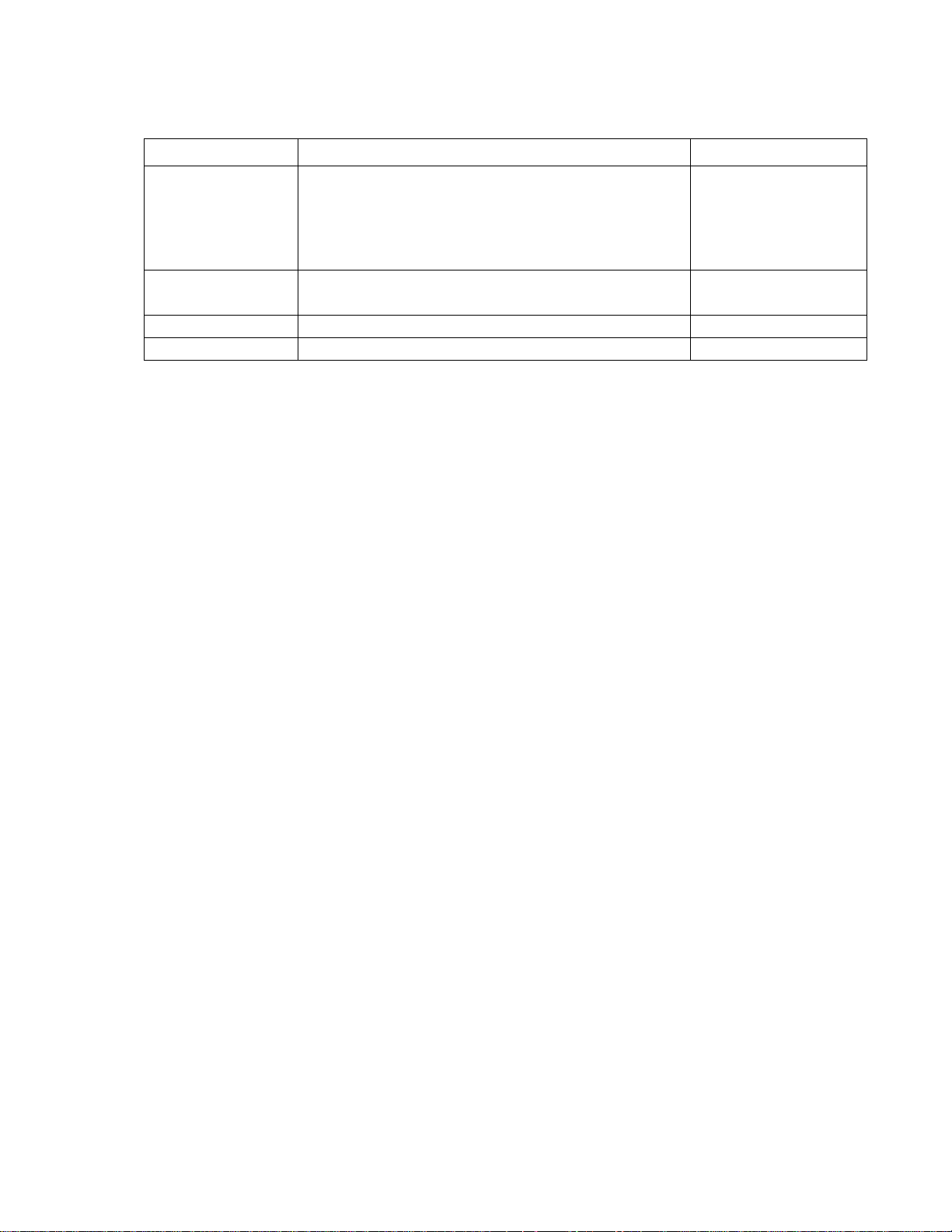
Component identification
SKU1
Item Description
1
2
3
4
5
6
7
8
9
10
11
12
13
14
15
16
1U chassis and access panel
HDD backplane
System fan (6)
M.2 assembly (2)
DIMM slot (24)
CPU 1 & heat sink
PSU (2)
PCIe card (2)
Riser board (2)
OCP mezzanine card
System board
CPU 0 & heat sink
HDD carrier (8)
Front control panel
2.5" SATA HDD (8)
Air baffle (2)
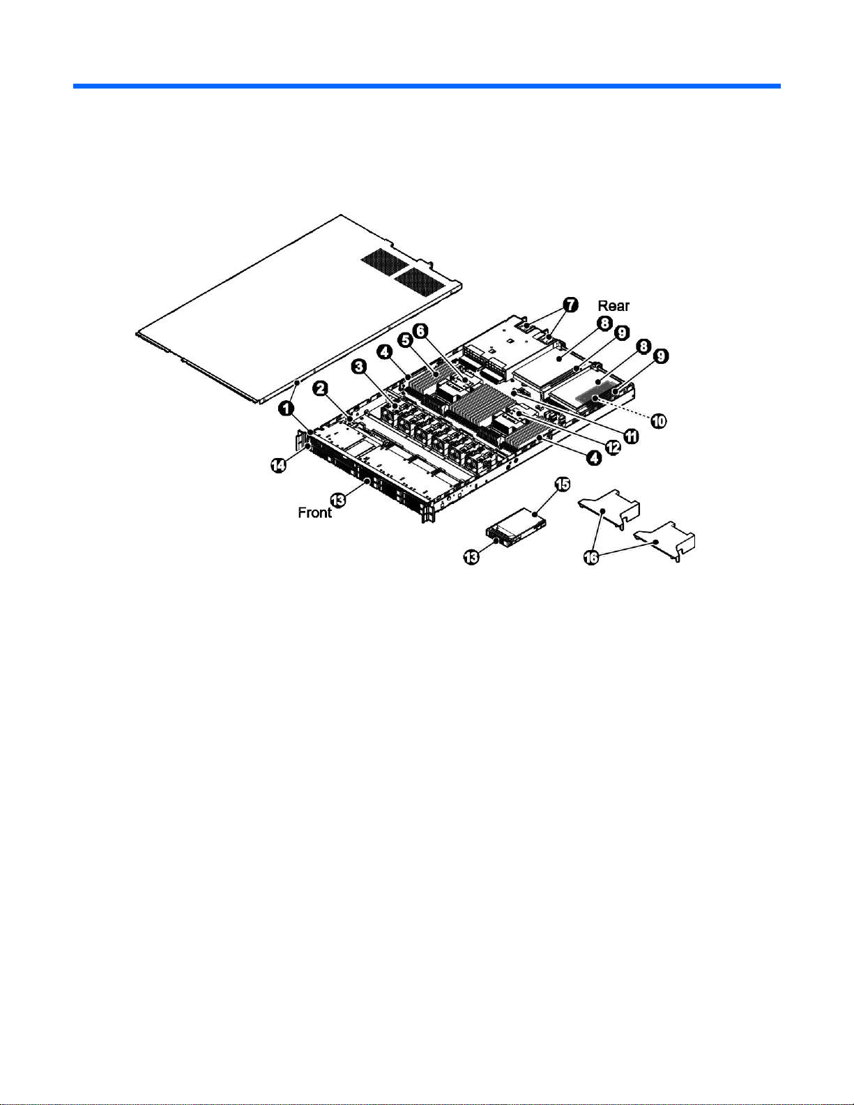
Component identification 9
SKU2
Item Description
1
2
3
4
5
6
7
8
9
10
11
12
13
14
15
16
17
1U chassis and access panel
HDD backplane
System fan (6)
M.2 assembly
DIMM slot (24)
CPU 1 & heat sink
PSU (2)
PCIe card
Riser board
OCP mezzanine card
Expander riser board
System board
CPU 0 & heat sink
HDD carrier (10)
Front control panel
2.5" U.2 HDD (10)
Air baffle (2)
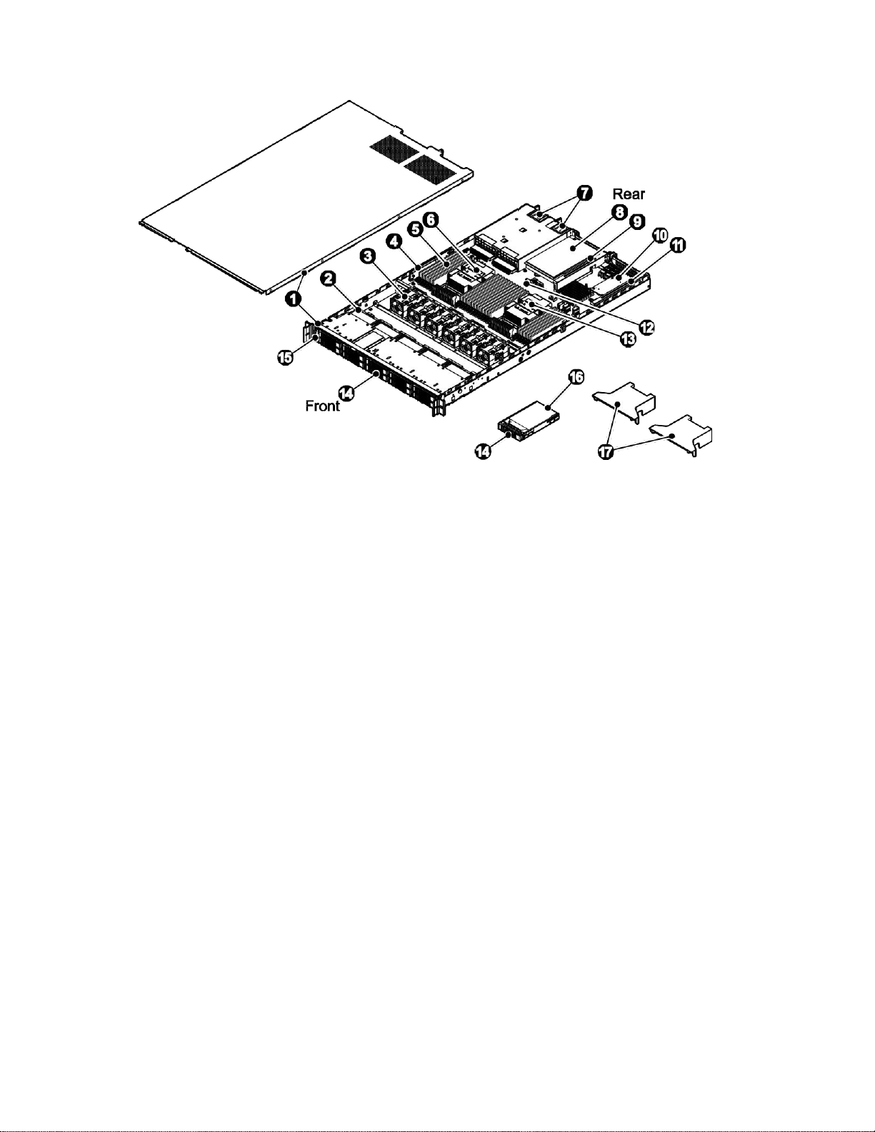
Component identification 10
Front panel components
Item
Description
1
Front control panel
2
2.5" HDD carrier (8)
Item
Description
1
Front control panel
2
2.5" HDD carrier (10)
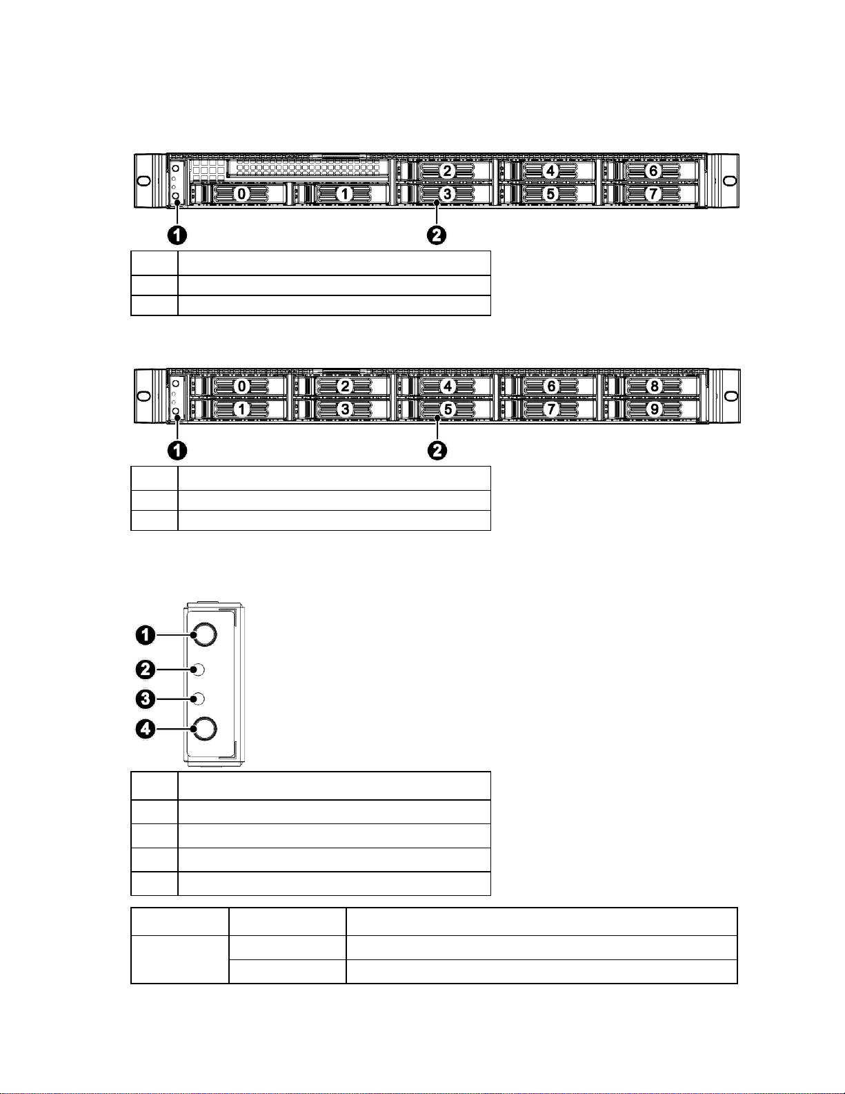
Item
Description
1
UID button and LED
2
Health LED
3
NIC LED
4
Power button and LED
LED Indicator
LED Color
Description
Power LED
Green
On: Power on
Yellow
On: In S5
SKU1
SKU2
Front control panel buttons and LED
Component identification 11
LED Indicator
LED Color
Description
UID LED
Blue
Blinking: System selected
Health LED
Red
On: Fault detected
Green
On: Normal operation
Orange
On: SEL event detected
NIC LED
Green
Blinking:
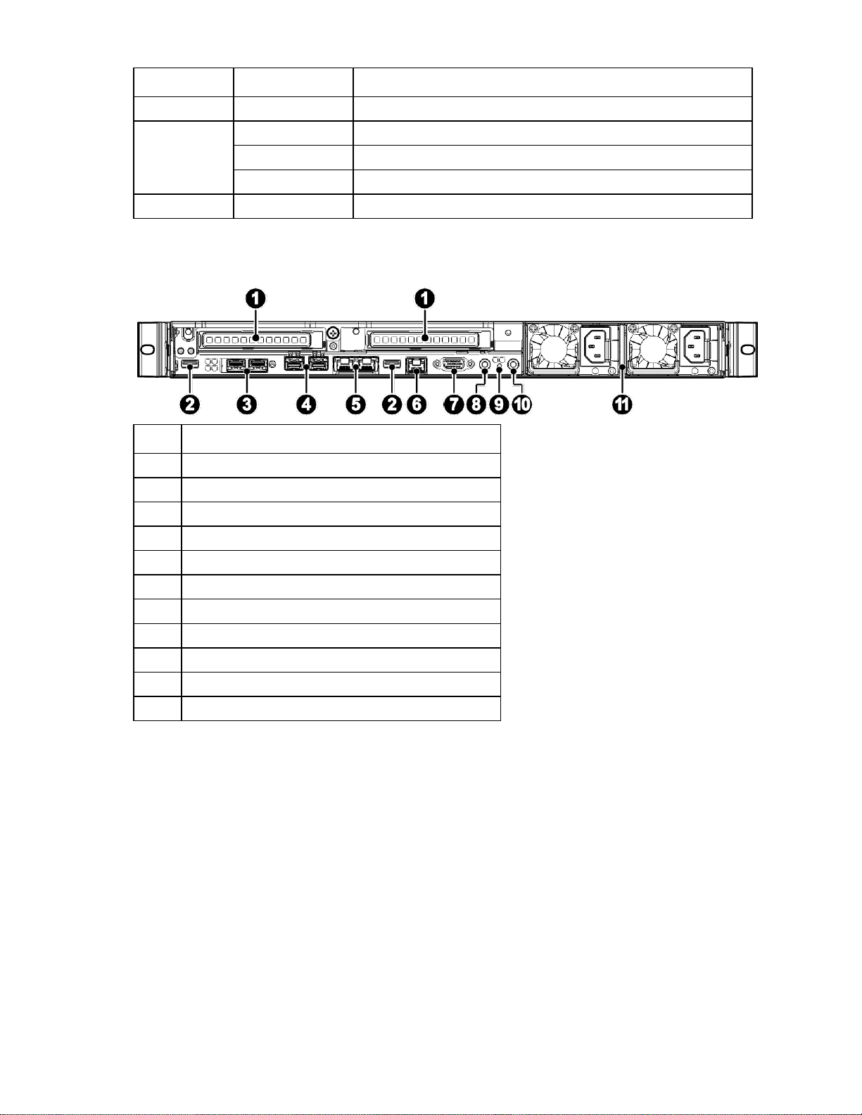
Item
Description
1
PCIe card (2)
2
USB
3
OCP mezzanine 25G port (2) (Optional)
4
Onboard SFP+ 10G port (2)
5
RJ45 (2)
6
IPMI
7
VGA
8
UID button and LED
9
Health LED
10
Power button and LED
11
PSU (2)
Rear panel components
Component identification 12
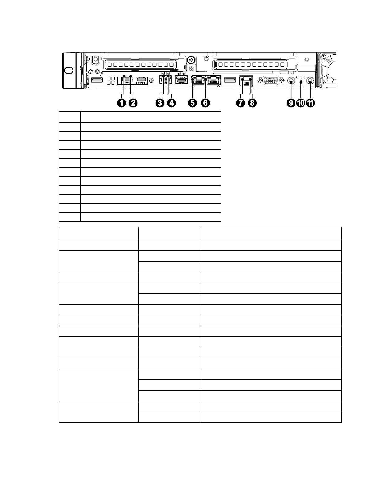
Rear panel buttonsand LED
Item
Description
1
25G zSFP+ Link/ Activity LED
2
25G zSFP+ speed LED
3
10G SFP+ Link/ Activity LED
4
10G SFP+ Speed LED
5
NIC Link/ Activity LED
6
NIC Link Speed LED
7
NIC Link/ Activity LED
8
NIC Link Speed LED
9
UID and reset button
10
Health LED
11
Power button and LED
LED Indicator
LED Color
Description
25G zSFP+ Link/ Activity LED
Green
On: Linked to network
25G zSFP+ speed LED
Green
On: 25G
Amber
On: Variable speed
10G SFP+ Link/ Activity LED
Green
Blinking: data sensed through port
10G SFP+ Speed LED
Green
On: 10G
Amber
On: Variable speed
NIC Link/ Activity LED
Green
Blinking: data sensed through port
NIC Link Speed LED
Green
On: 1G
NIC Link/ Activity LED
Green
Blinking: data sensed through port
NIC Link Speed LED
Green
On: 1G
Amber
UID LED
Blue
System selected
Health LED
Red
On: Fault detected
Green
On: Active
Orange
On: Status degrading
Power LED
Green
On: Power on
Amber
On: In S5
Component identification 13
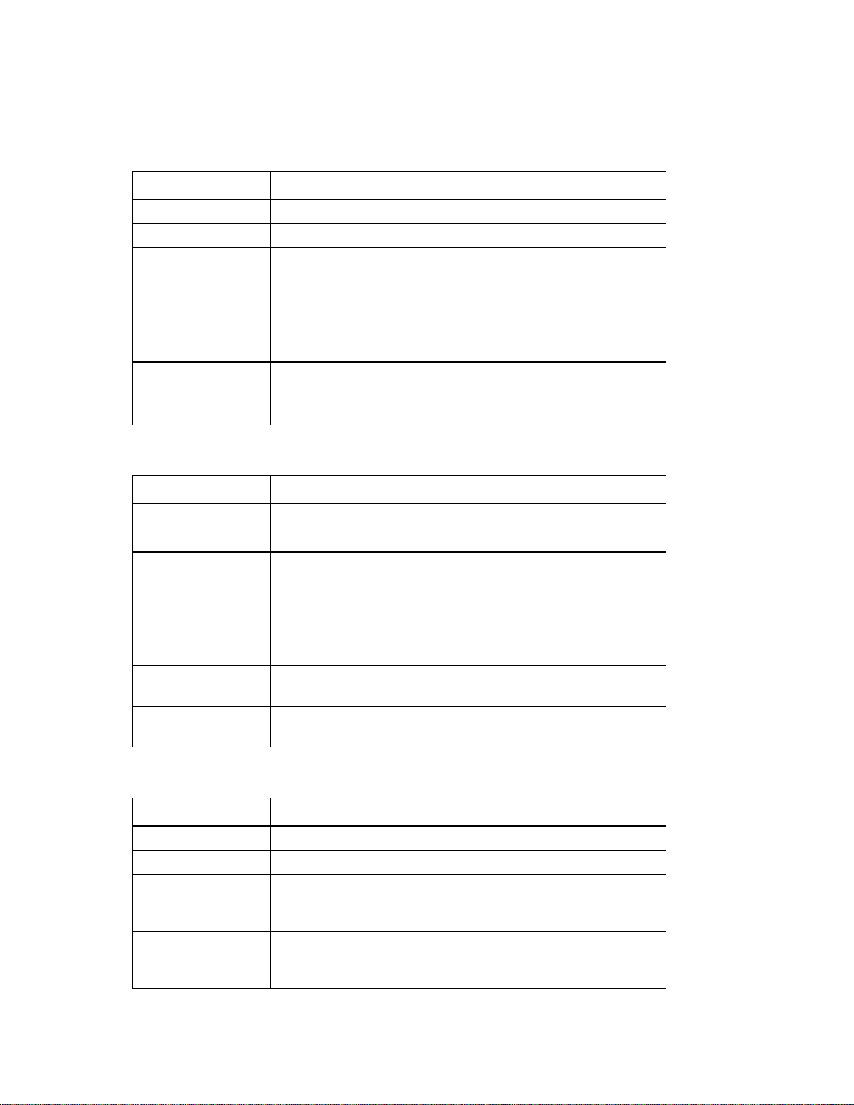
Power supply LEDs
LED Appearance
Description
Off
No AC power
Green
Output on, normal
Green blinking (1
sec/ on, 1 sec/ off,
0.5Hz)
Standby mode normal
Green blinking (0.25
sec/ on, 0.25 sec/ off,
2Hz)
Sleep PSU in cold redundant/ off mode
Amber
Standby mode with OTP range
12V fault (include OVP, UVP, OCP, SCP and OTP)
Fan lock 15 sec including stand-by mode
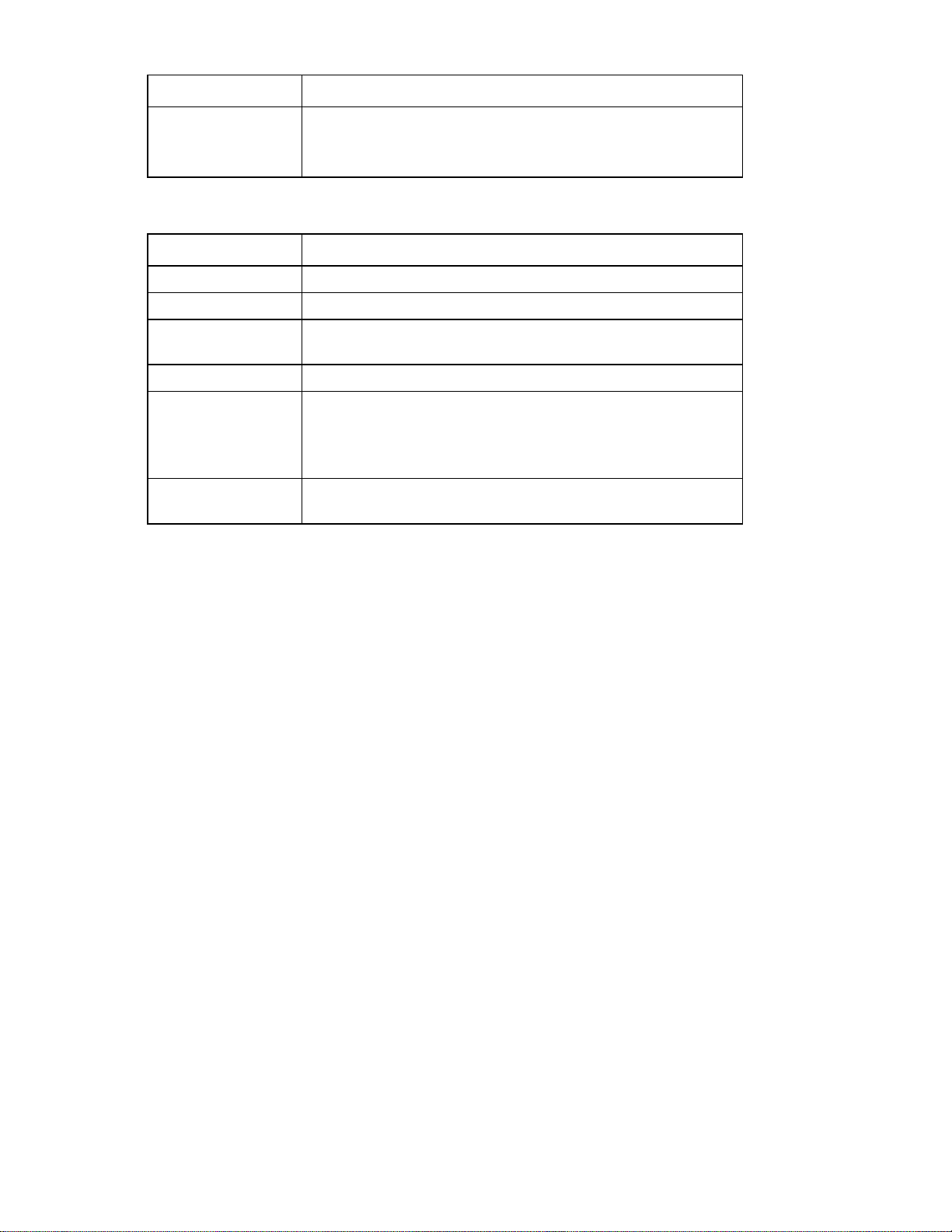
LED Appearance
Description
Off
No AC power to power supply
Green
+12V output on, normal
Green blinking (1
sec/ on, 1 sec/ off,
0.5Hz)
AC present/ only +12VSB on (PS off) or PSU in smart standby mode
Green blinking (0.25
sec/ on, 0.25 sec/ off,
2Hz)
Power supply FW updating
Amber
Power supply critical event causing a shutdown; OTP, OCP, UVP, OVP
fan fail
Amber blink (1Hz)
Power supply warning events where the power supply continues to
operate; high temp, high power, high current, slow fan
LED Appearance
Description
Off
No AC power to all power supplies
Green
Output on, normal
Green blinking (1
sec/ on, 1 sec/ off,
0.5Hz)
Standby mode normal
Green blinking (0.25
sec/ on, 0.25 sec/ off,
2Hz)
Sleep PSU in cold redundant/ off mode
The power supply comes with one LED and the LED is visible from the rear of the power supply.
PS-2801-9L
DPS-800AB-37 A
PS-2551 -9L1
Component identification 14
LED Appearance
Description
Amber
Standby mode with OTP range
12V fault (include OVP, UVP, OCP, SCP and OTP)
Fan lock 15 sec including stand-by mode
LED Appearance
Description
Off
No AC power to all power supplies
Green
Output on, normal
Green blink (1Hz)
AC presents/ only +12VSB on (PS off) or PSU in smart redundant
state/ off line mode
Green blink (2Hz)
Power supply FW updating
Amber
AC cord unplugged or AC power lost; with a second power supply
in parallel still with AC input power
Power supply critical event causing a shutdown; failure, OCP, SC,
OVP, fan fail, OTP
Amber blink (1Hz)
Power supply warning events where the power supply continues to
operate; high temp, high power, high current, slow fan
S550E004L
Component identification 15
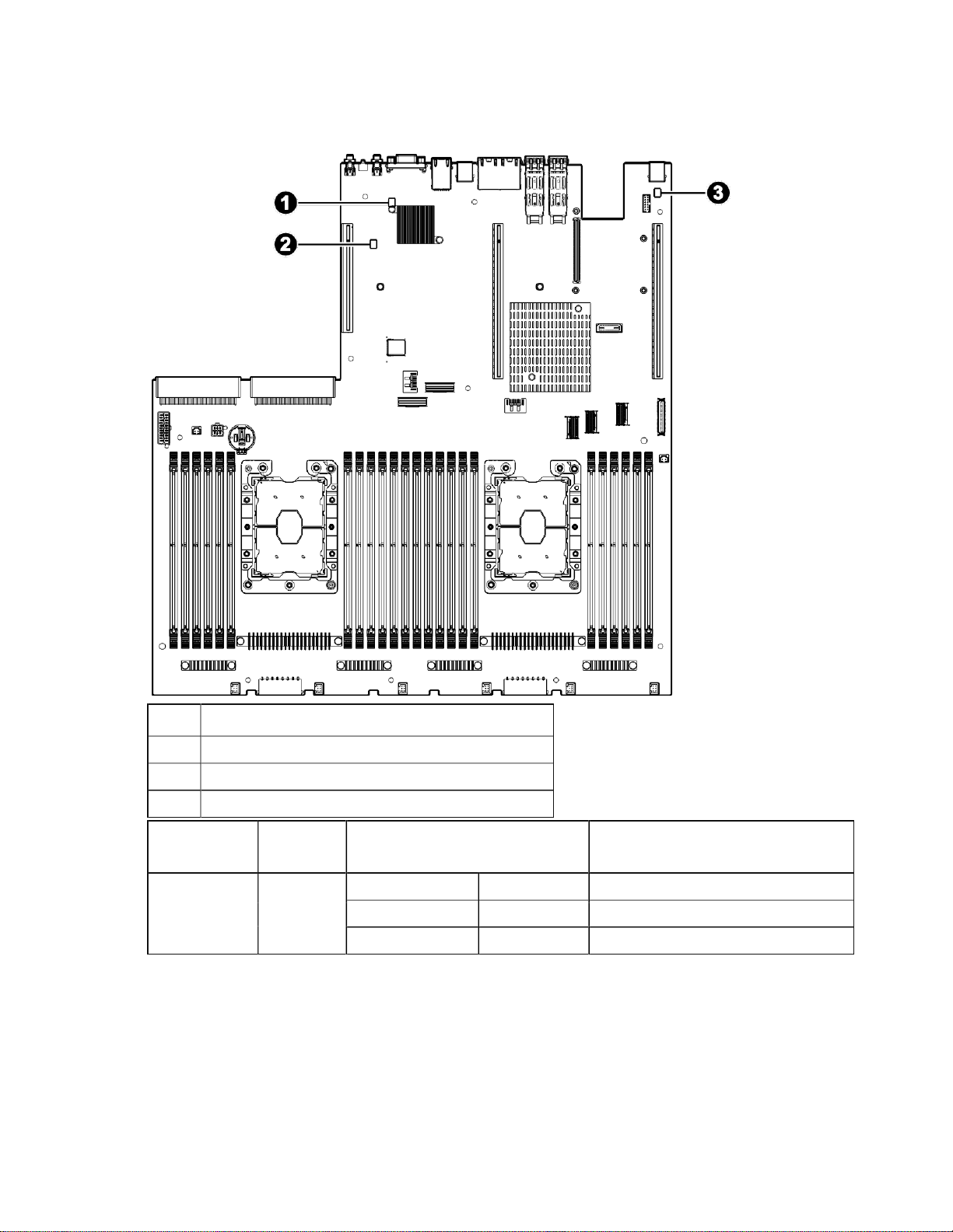
Board LEDs
See the following illustration to locate the system board LEDindicators:
Item Description
1
2
3
LED Name Voltage
CR24 BMC Heart-Beat LED
CR21 Speaker LED
CR33 HDD activity LED
LED Color State Description
Sources
BMC Heart-Beat
LED
P3V3 Green

Component identification 16
LED Name
Voltage
Sources
LED Color State
Description
Speaker LED
P5V
Yellow
HDD activity
LED
P3V3
Yellow
Component identification 17
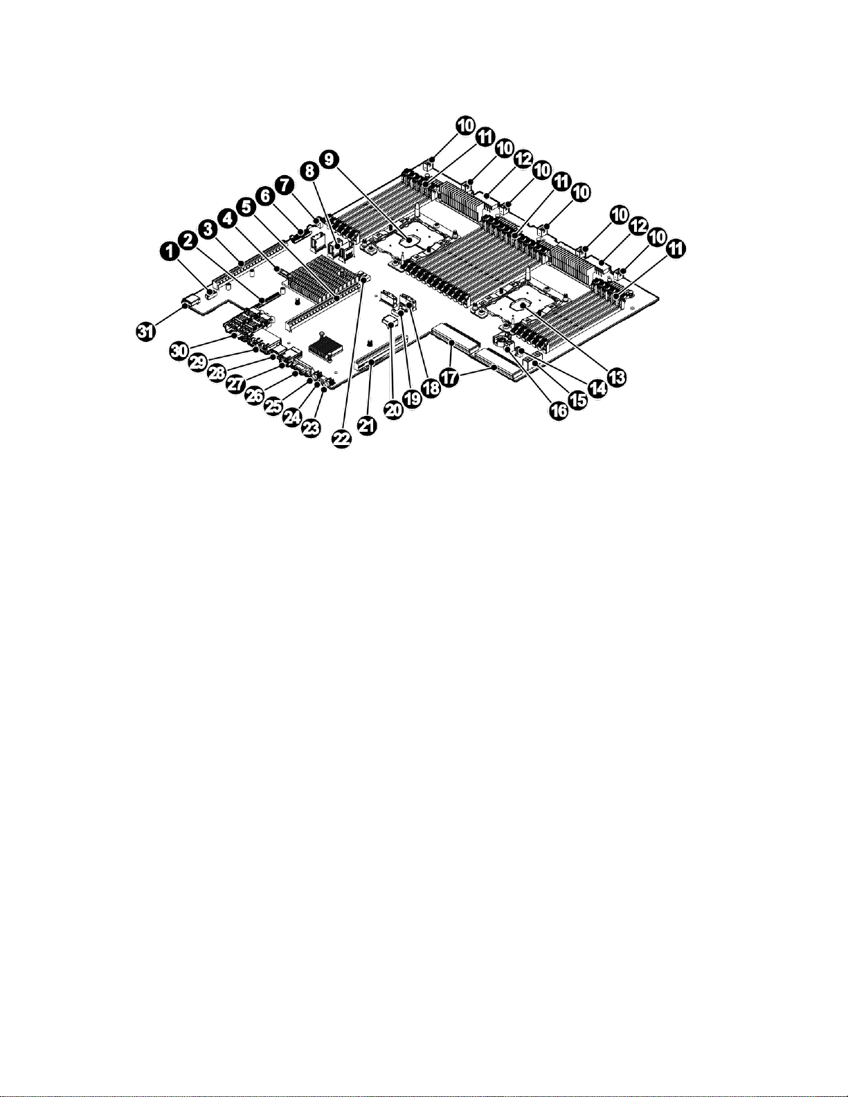
System board components
Item Description
1
2
3
4
5
6
7
8
9
10
11
12
13
14
15
16
17
18
19
20
21
I2C pin header
OCP mezzanine connector
CPU 0 PCIe x24 slot
XDP
CPU 1 PCIe x24 slot
FPIO connector
M.2 power connector
MiniSAS connector
CPU 0 socket
System fan header(6)
DIMM slot (24)
HDD power connector
CPU 1 socket
M.2 power connector
GPU power connector
Rear backplane power connector
PSU connector (2)
SLIMLINEconnector
M.2 SATA connector
Internal USB 3.0
CPU 1 PCIe x16 slot
Component identification 18
Item
Description
22
M.2 SATA connector
23
Power button and LED
24
Health LED
25
UID and reset button
26
VGA
27
IPMI
28
USB
29
RJ45 (2)
30
Onboard SFP+ 10G port (2)
31
USB
LED Appearance
Description
Off
HDD not present
Green blinking
HDD read/ write activity
Blue solid
HDD present and Online
Blue blinking (4Hz)
HDD locate
Red solid
HDD fail
Red blinking (1Hz)
HDD rebuild
HDD carrier LED definitions
Each drive tray supports two light pipes to direct light from the drive status LEDs on the backplane to the
face of the tray, allowing it to be viewable from the front of the system.
Important: The fault LED functionis only being supported when an HBA/ RAID card is installed.
Component identification 19
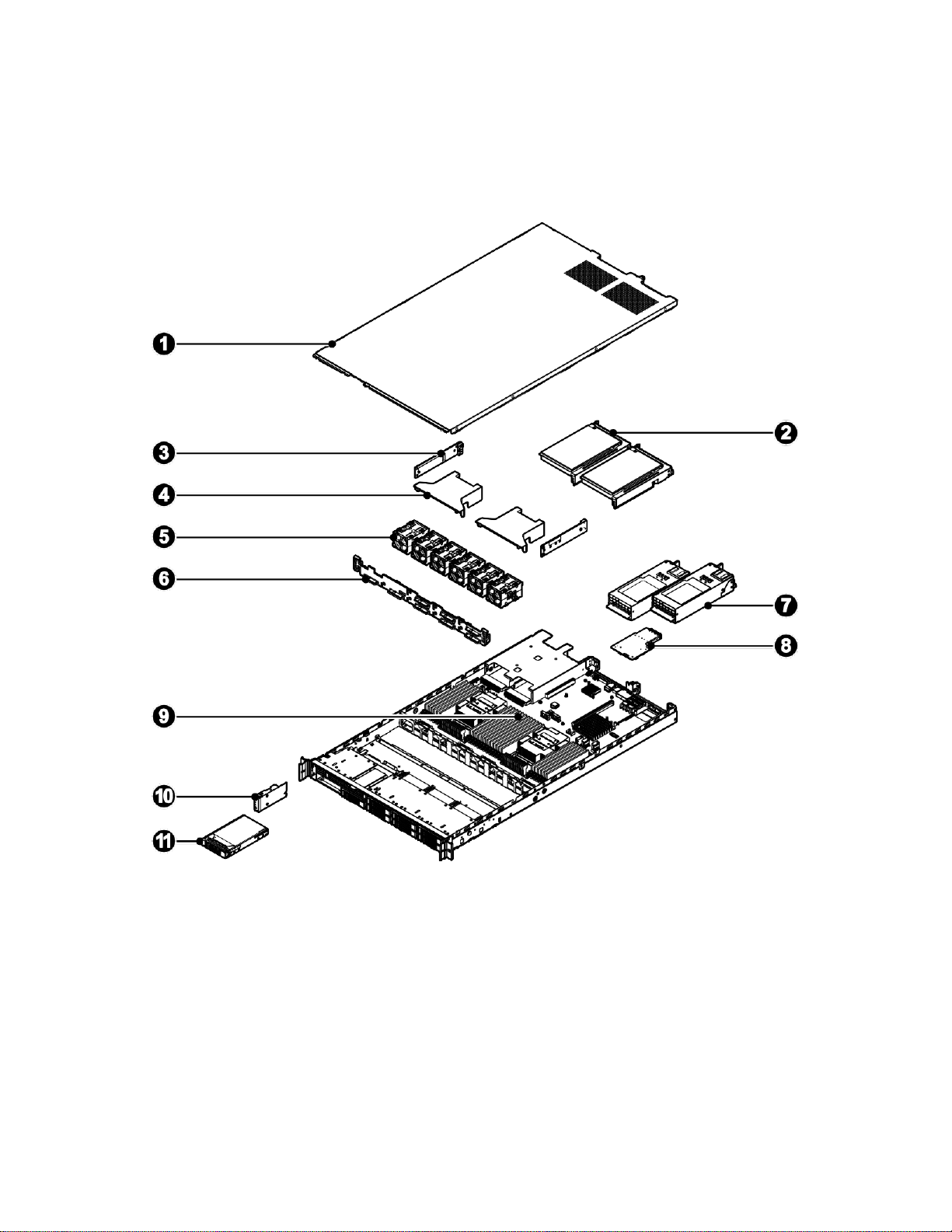
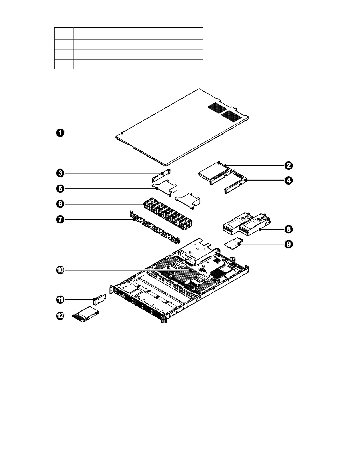
System components
The following figure shows specific components of the server systemB. efore initiating any service
procedures, familiarize yourself with the system and its components as illustrated in the following figure.
SKU1
Item Description
1
2
3
4
5
6
7
8
Access panel
Riser assembly
M.2 assembly (2)
Air baffle (2)
System fan (6)
HDD backplane
PSU (2)
OCP mezzanine card
Component identification 20
Item Description
9
10
11
System board
Front control panel
2.5" HDD (8)
SKU2
Item Description
1
2
3
4
5
6
7
Access panel
Riser assembly
M.2 assembly
Expander riser board
Air baffle (2)
System fan (6)
HDD backplane

Component identification 21
Item
Description
8
PSU (2)
9
OCP mezzanine card
10
System board
11
Front control panel
12
2.5" HDD (8)

Operations 22
Operations
Powering up the server
The following procedure assumes that at least one power cord is connected to the server to supply power
to the server and that the server has been previously powered on.
1. Verify that the power cord is connected to the server and that the LEDs on the power supply unit and
front control panel are lit. The LEDs turn on immediately indicating the server is connected to power
and that the server is in a standby power state. If the power LED is off, this indicates that the server is
not connected to power or has been powered off during standby mode.
2. Power up the server
o Powering on locally: Press and release the power button on the front control panel.
o Powering on remotely (BMC web interface): Log in to the BMC web interface and select power on
from the power control action list box.
o Powering on remotely (BMC CLI): Log in to the BMC CLI and execute an IPMI power up system
command.
Powering down the server
The following procedures demonstrate how to shut down the server and verify the power status.
Shutting down the server
Graceful shutdown
To perform a graceful shutdown: Save all open files, network service, and close all applications prior
to shutting down.
Stop or terminate all necessary system processes to bring down the operating system and power off
the compute node.
Press and release the power button on the front panel of ACPI-enabled (Advanced Configuration and
Power Interface) operating systems to perform an orderly shutdown of the operating system. Servers
not running ACPI-enabled operating systems will shutdown immediately.
Emergency shutdown
CAUTION: All applications and files will be closed without saving changes, file system
corruption might occur.
To perform an emergency shutdown, press and hold down the power button on the front panel for at least
five seconds to perform a hard shut down. The server then enters standby power mode.
BMC CLI shutdown
Log in to the BMC and execute the IPMI command to shut down the server.

Operations 23
Verifying the power status
The power LED indicators on the server are off when the server is powered down. Verify the server is
powered down before removing or servicing any server components.

Installation 24
Installation
Safety measures
Static electricity discharges can damage computer components and electronic circuit boards. Working on
computers that are still connected to a power supply can be extremely dangerous. Follow these guidelines
to avoid self-injury and damage to the computer:
Always disconnect the server from the power outlet when working inside of the computer case.
If possible, wear a grounded wrist strap when working inside the computer case. Alternatively,
discharge any static electricity by touching the bare metal chassis of the computer case, or the bare
metal body of any other grounded appliance.
Hold electronic circuit boards only by the edges. Do not touch the components on the board unless it
is necessary to do so. Do not flex or stress the circuit board.
Leave all components inside the static-proof packaging until ready to use the component for the
installation.
Identifying the contents of the server shipping carton
Unpack the server shipping carton and locate the materials for installation.
The shipping contents include:
Server
Power cord (optional)
Rack-mounting hardware (optional)
In addition to the supplied items, you might need:
Operating system or application software
Hardware options
Installation 25
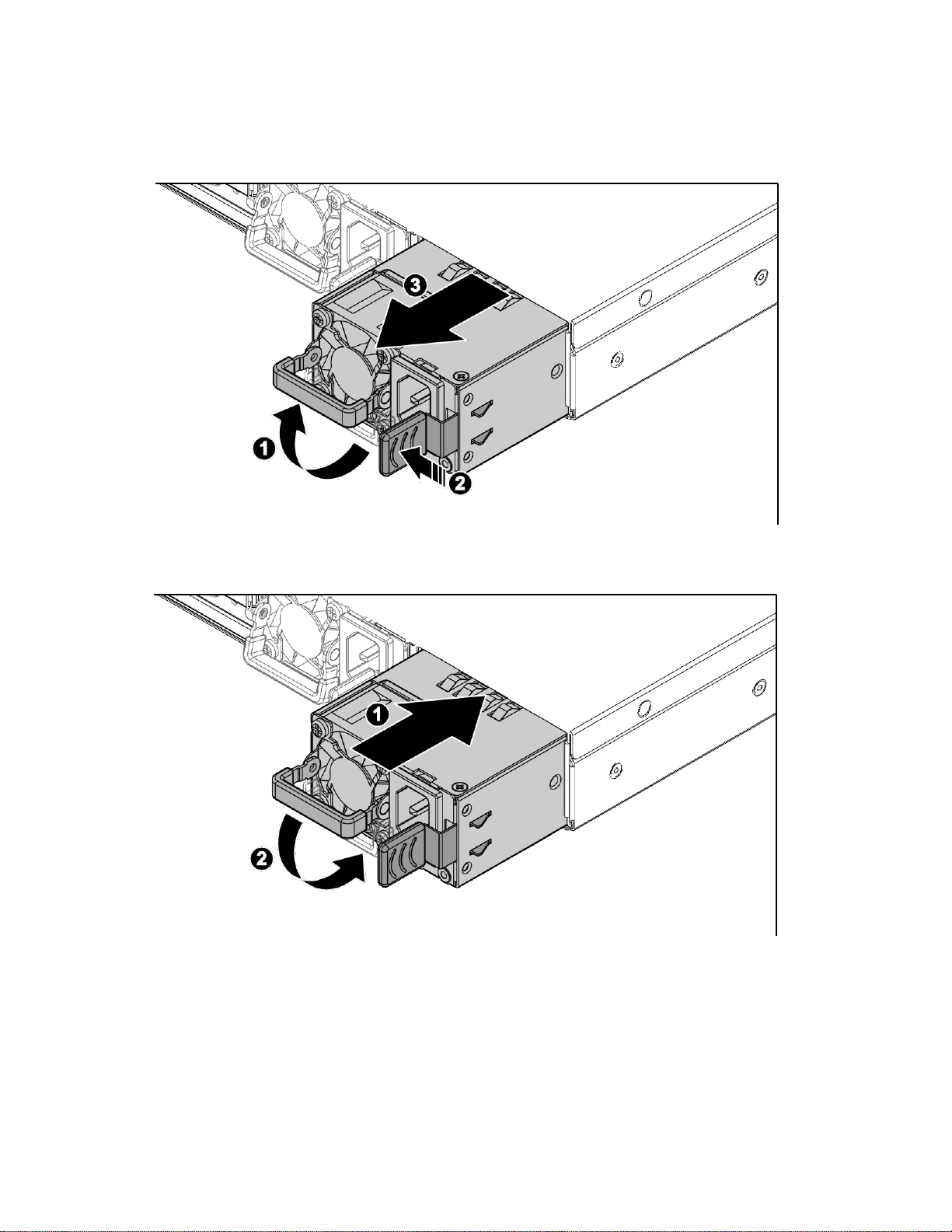
Redundant power supply units
Removing a redundant power supply unit
Installing a redundant power supply unit
Installation 26
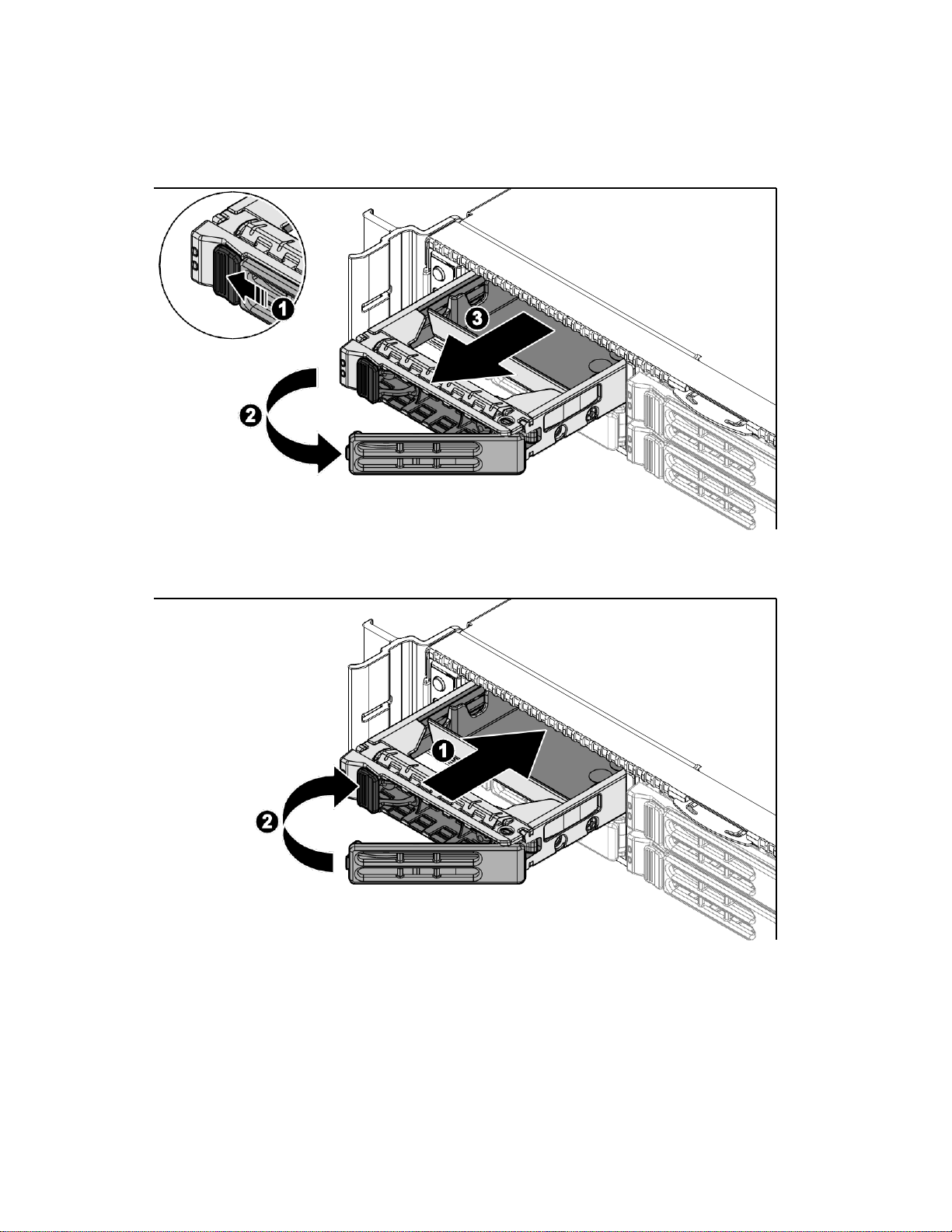
Hard disk drives
Removing a 2.5" HDD assembly
Installing a 2.5" HDD assembly
Verify that the drive is fully seated.
Installation 27
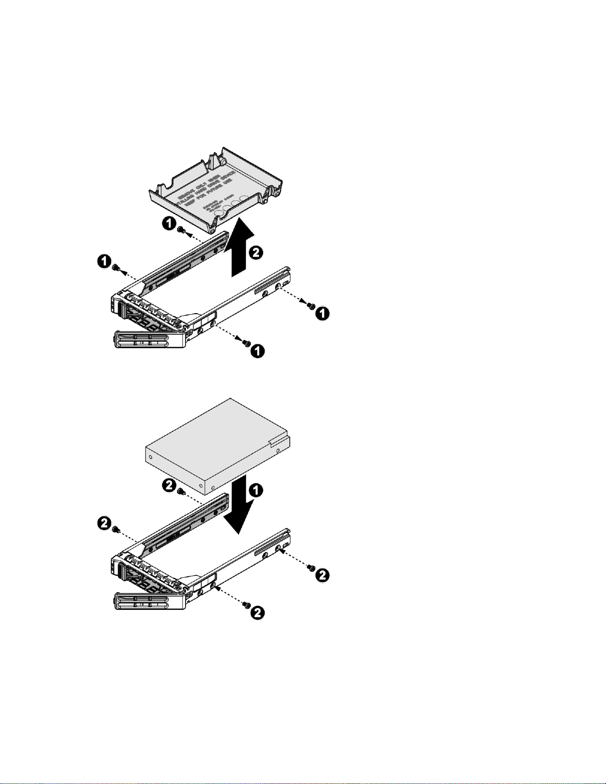
Installing a 2.5" HDD module
To install a 2.5" HDD module:
1. Remove the2.5" HDD assembly (on page 26).
2. Remove the screws securing the filler panel to the HDD carrier.
3. Remove the filler panel from the HDD carrier.
4. Align the HDD in the HDD carrier with the connectors facing the opening of the carrier.
5. Secure the HDD to the HDD carrier with screws.
6. Install the 2.5" HDD assembly (on page26).
Installation 28
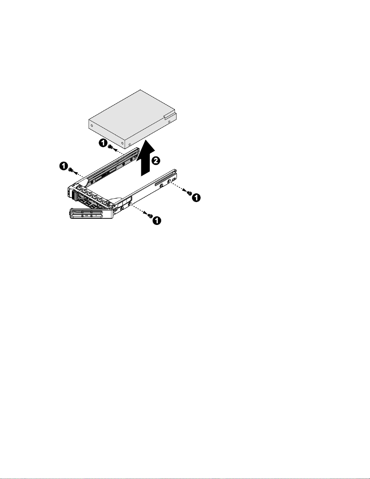
Removing a 2.5" HDD module
To remove a 2.5" HDD module:
1. Remove the2.5" HDD assembly (on page 26).
2. Remove the screws securing the HDD to the HDD carrier.
3. Remove the HDD from the HDD carrier.
Installation 29
Access panel
Removing an access panel
CAUTION: Be sure that the server is powered off and the AC power cords are disconnected
from the server power supplies.
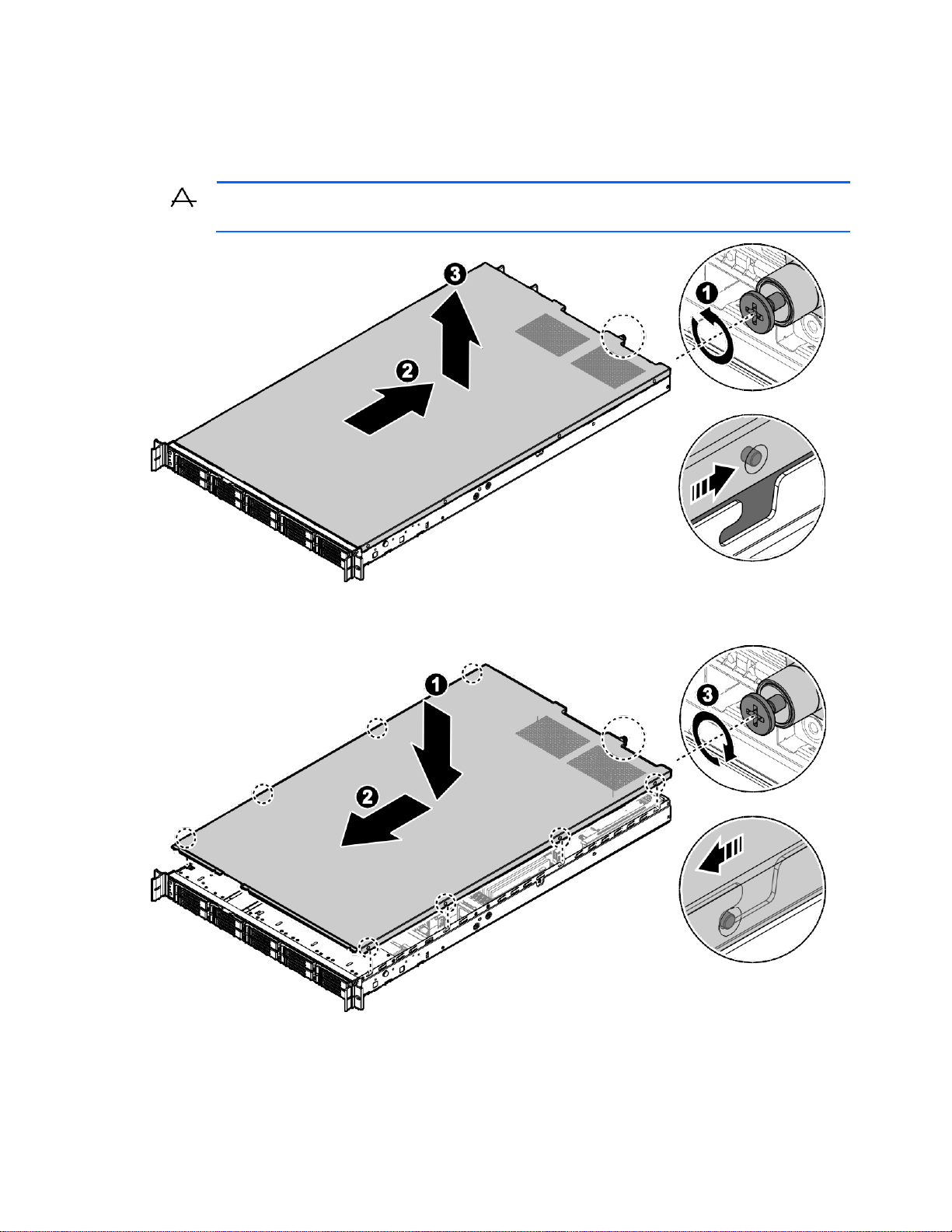
Installing an access panel

Installation 30
Air baffle
Removing an air baffle
To remove an air baffle:
1. Power off the server and detach all of the power cords from the power supplies.
2. Remove the access panel (on page 29).
3. If the cable is locked on the air baffle, remove it.
4. Locate the air baffle and remove it from the chassis.
CAUTION: To avoid damaging server components, do not use force when removing the air
baffle.

Installation 31
Installing an air baffle
To install an air baffle:
1. Position the air baffle over the chassis. Align it with the slits on the top of the fan cage. Make sure the
air baffle does not touch the DIMM modules during the installation procedure.
CAUTION: To avoid damaging server components, do not use force when installing the air
baffle. Be sure that all DIMM latches are locked to avoid damaging the components.
2. Lower the air baffle into the chassis, and gently press down on the front of the ari baffle to ensure the
tabs on the air baffle are inserted through the slits on the fan cage.
3. Install the accesspanel (on page 29).

Installation 32
System fans
Cable routing
Removing a system fan
To remove a system fan:
1. Power off the server and detach all of the power cords from the power supplies.
2. Remove the access panel (on page 29).
3. Release the fan assembly from the chassis, and then remove it.
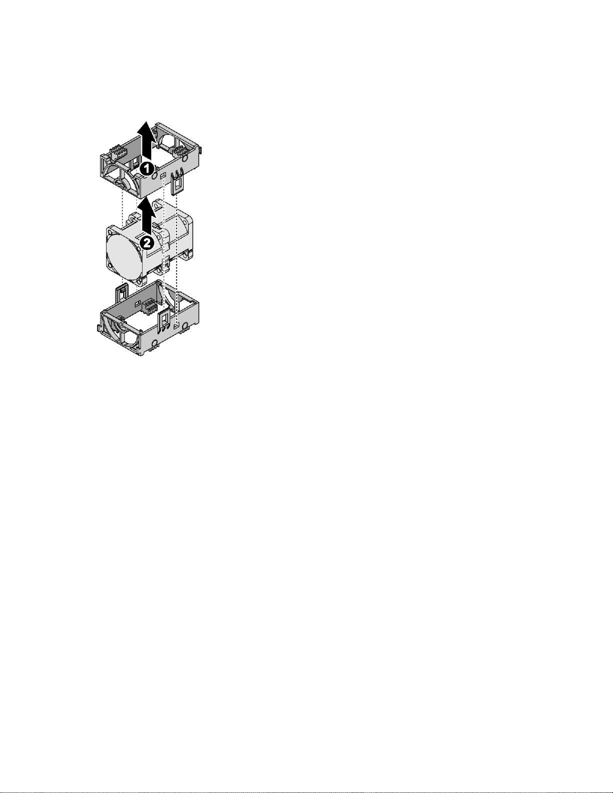
Installation 33
4. Unlock the fan assembly bracket.
5. Remove the upper fan assembly bracket.
6. Lift the fan module.
7. Repeat the process for the remaining fan modules.

Installation 34
Installing a system fan
To install a system fan:
CAUTION: Avoid damaging the fan cable.
1. Unlock the fan assembly bracket.
2. Insert the fan module into the assembly bracket as shown in the following figure.
3. Insert the upper assembly bracket, and then lock it.
4. Route the fan cable.

Installation 35
5. Repeat the steps for the remaining fan modules.
6. Align the fan assembly with the chassis and the cable facing to the front of the chassis.
7. Insert the fan assembly into the chassis.
8. Install the access panel (on page 29).

Installation 36
M.2 adapters
Removing an M.2 adapter
To remove an M.2 adapter:
1. Power off the server and detach all of the power cords from the power supplies.
2. Remove the access panel (on page29).
3. Disconnect the cables from the M.2 adapter.
4. Remove the screws securing the M.2adapter.
5. Remove the M.2 adapter.

Installation 37
Installing an M.2 adapter
To install an M.2 adapter:
1. Align the holes on the M.2 adapter with the holes on the chassis.
2. Secure the M.2 adapter to the chassis with screws.
3. Connect the cables to the M.2 adapter.
4. Install the access panel (on page29).

Installation 38
M.2 cards
Installing an M.2 card
To install an M.2 card:
1. Power off the server and detach all of the power cords from the power supplies.
2. Remove the access panel (on page29).
3. Remove the M.2 adapter (on page 36).
4. Align the slit on the M.2 card connector pins with the protrusion on the connector.
5. Slide the M.2 card into the connector until it is fully inserted.
6. Push the M.2 card towards the adapter and hold it in place.
7. Secure the M2 card to M.2 adapter with a screw.
8. Install the M.2 adapter (on page 37).
9. Install the access panel (on page29).
Removing an M.2 card
To remove an M.2 card:
1. Power off the server and detach all of the power cords from the power supplies.
2. Remove the access panel (on page29).
3. Remove the M.2 adapter (on page 36).
4. Remove the screw securing the M.2 card.
5. The M.2 card pops out. Grasp it by the edges and slide it out.

Installation 39
Hard disk drive backplane
Removing a SATA HDD (SKU1) backplane
This section applies to SKU1 model only.
To remove a SATA HDD backplane:
1. Power off the server and detach all of the power cords from the power supplies.
2. Remove the access panel (on page29).
3. Remove all HDD assemblies(on page 26).
4. Disconnect the cables from the HDD backplane.
5. Remove the screws securing the HDD backplane assembly to the chassis.
6. Release the HDD backplane assembly from the guide tabs on the chassis, and then remove the HDD
backplane.

Installation 40
7. Remove the screws securing the HDD backplane to the HDD assembly bracket.
8. Remove the HDD backplane.
Installing a SATA HDD (SKU1) backplane
This section applies to SKU1 model only.
To install a SATA HDD backplane:
1. Align the screw holes on the HDD backplane with the screw holes on HDD assembly bracket.
2. Secure the HDD backplane and HDD assembly bracket with the screws.

Installation 41
3. Align the screw holes on the HDD backplane assembly with the screw holes on the chassis, the HDD
SAS connectors must face inward.
4. Install the HDD backplane assembly to the guide tabs on the chassis.
5. Secure the HDD backplane assembly and the chassis with the screws.
6. Connect the cables to the HDD backplane.
7. Install all HDD assemblies(on page 26).
8. Install the access panel (on page29).

Installation 42
Removing a U.2 HDD (SKU2) backplane
This section applies to SKU2 model only.
To remove a U.2 HDD backplane:
1. Power off the server and detach all of the power cords from the power supplies.
2. Remove the access panel (on page29).
3. Remove all HDD assemblies(on page 26).
4. Disconnect the cables from the HDD backplane.
5. Remove the screws securing the HDD backplane assembly to thechassis.
6. Release the HDD backplane assembly from the guide tabs on the chassis, and then remove the HDD
backplane.

Installation 43
7. Remove the screws securing the HDD backplane to the HDD assembly bracket.
8. Remove the HDD backplane.
Installing a U.2 HDD (SKU2) backplane
This section applies to SKU2 model only.
To install a U.2 HDD HDD backplane:
1. Align the screw holes on the HDD backplane with the screw holes on HDD assembly bracket.
2. Secure the HDD backplane and HDD assembly bracket with the screws.

Installation 44
3. Align the screw holes on the HDD backplane assembly with the screw holes on the chassis, the HDD
SAS connectors must face inward.
4. Install the HDD backplane assembly to the guide tabs on the chassis.
5. Secure the HDD backplane assembly and the chassis with the screws.
6. Connect the cables to the HDD backplane.
7. Install all HDD assemblies(on page 26).
8. Install the access panel (on page29).

Installation 45
Front control boards
Removing a front control board
To remove a front control board:
1. Power off the server and detach all of the power cords from the power supplies.
2. Remove the access panel (on page 29).
3. Remove all HDD assemblies(on page 26).
4. Remove the HDD backplane (on page 39 or page 42).
5. Disconnect the cable fromthe system board.
6. Remove the screw securing the front control board assembly to the chassis.
7. Pull the front control board assembly through the chassis bay. Make sure the cable does not get
caught in the bay while removing the assembly.
8. Remove thescrews securing thefront control board to the front control bracket.
9. Remove thefront control board.

Installation 46
Installing a front control board
To install a front control board:
1. Align the LEDs on the front control board with the slots on the front control brackte.
2. Install the front control board into the front control bracket.
3. Secure the front control board to the front control bracket with screws.
4. Slide the cable through the chassis bay and pull it through while sliding the front control board into
the chassis.
5. While pulling the cable connector, slide the front control board assembly into the chassis until it is
flush in the bay.
6. Secure the front control board assembly to the chassis with a screw.
7. Connect the cable to the system board.
8. Install the HDD backplane (on page 40 or page 43).
9. Install all HDD assemblies(on page 26).
10. Install the access panel (on page29).

Installation 47
PCIe cards
Removing a PCIe card
To remove a PCIe card:
1. Power down the server, and then detach all of the power cords from the power supplies.
2. Remove the access panel (on page29).
3. Disconnect the cables from the PCIe assembly.
4. Grasp the PCIe assembly, and then gently lift the PCIe assembly up to removeth e PCIe assembly from
the chassis.
5. Remove the screw securing the PCIe card to the riser bracket.
6. Remove the PCIe card from the riser board.

Installation 48
Installing a PCIe card
To install a PCIe card:
1. Orient the PCIe card with the riser guide slot and insert the connector into the riser slot. Make sure the
connector is flush in the slot.
2. Secure the PCIe card to the riser bracket with a screw.
3. Gently insert the PCIe assembly into the PCIe slot on the system boardM.
tab on the bracket is inserted in the rear and middle side of the chassis.
ake sure the standoff and
4. Connect the cables to the PCIe assembly.
5. Install the access panel (on page29).

Installation 49
Riser boards
Removing a riser board
To remove a riser board:
1. Power down the server, and then detach all of the power cords from the power supplies.
2. Remove the access panel (on page 29).
3. Remove the PCIe card (on page 47).
4. Remove the screws securing the riser board to the riser bracket.
5. Remove the riser board from the bracket.
Installing a riser board
To install a riser board:
1. Remove a screw securing the dummy bracket to the riser bracket.
2. Remove the dummy bracket from the riser bracket if necessary.

Installation 50
3. Position the riser board in the bracket. The slots are positioned outward, see the followingillustration.
The screw holes on the riser board and bracket align indicating a correct installation.
4. Secure the riser board to the riser bracket with screws.
5. Install the PCIe card (on page 48).
6. Install the access panel (on page 29).
Removing an expander board
This section applies to SKU2 model only.
To remove an expander board:
1. Power down the server, and then detach all of the power cords from the power supplies.
2. Remove the access panel (on page29).
3. Disconnect the cables from the expander assembly.
4. Grasp the expander assembly, and then gently lift theexpander assembly up to remove theexpander
assembly from the chassis.

Installation 51
5. Remove the screw securing the expander board to the riser bracket.
6. Remove the expander board from the bracket.
Installing an expander board
This section applies to SKU2 model only.
To install an expander board:
1. Position the expander board on the riser bracket. The contacts on the expander baord face outward.
2. Slide the expander board in place. The tab on the expander board is inserted in the rear of the riser
bracket. The screw holes on the board and bracket line up indicating a correct alignment.
3. Secure the expander board to the riser bracket with a screw.

Installation 52
4. Gently insert the expander assembly into the PCIe slot on the system board. Make sure the standoff is
locked in place on the chassis.
5. Connect the cables to the expander assembly.
6. Install the access panel (on page29).

Installation 53
OCP mezzanine cards
Removing an OCP mezzanine card
To remove an OCP mezzanine card:
1. Power off the server, and then detach all of the power cords from the power supplies.
2. Remove the access panel (on page 29).
3. Remove the PCIe card (on page 47).
4. Remove the screws securing the OCP mezzanine card to the system board.
5. Remove the OCP mezzanine card.

Installation 54
Installing an OCP mezzanine card
To install an OCP mezzanine card:
1. Align the connector on the OCP mezzanine card with the slot on the system board.
2. Gently install the OCP mezzanine card.
3. Secure the OCP mezzanine card to the chassis with screws.
4. Install the PCIe card (on page48).
5. Install the access panel (on page 29).

Installation 55
Memory modules
Removing a memory module
The system board includes 24 DIMM slots (six channels per processor, each channel contains two memory
slots) for the installation of DDR4 2400/ 2666 MHz memory.
To remove a memory module:
1. Power off the server, and then detach all of the power cords from the power supplies.
2. Remove the access panel (on page 29).
3. Remove an air baffle (on page 30).
4. Push the locking latches of the DIMM slot downward and outward to eject the memory module.
5. Remove the memory module.
6. Repeat the process for the additional memory modules.

Installation 56
Installing a memory module
The system board includes 24 DIMM slots (six channels per processor, each channel contains two memory
slots) for the installation of DDR4 2400/ 2666 MHz memory.
To install a memory module:
1. Pull the locking latches of the DIMM slot outward.
2. Place the memory module into the socket so the notch and obstruction are aligned.
3. Press the edge connector of the memory module into the slot.
Press down firmly so that the locking latches of the DIMM slot are levered upward to secure the
memory module.
4. Repeat for the additional memory modules.
5. Install an air baffle (on page 31).
6. Install the access panel (on page 29).

Installation 57
Processors
Passive heat sinks cool processors. To achieve optimal cooling performance , TIM must be installed
between the processor and heat sink. The mechanical performance of the heat sink is designed to meet the
requirements of Intel processors. The heat sink is necessary to maintain chipset temperature at or below
temperature limits.
Removing a processor
CAUTION: ESD protection must be worn during the procedure to avoid damaging the
components.
To remove a processor:
1. Remove the access panel (on page29).
2. Remove the air baffle (on page 30).
3. Sequentially loosen the screws on the heat sink.
4. Lift up the processor assembly (heat sink, processor and CPU carrier) to remove.

Installation 58
5. Turn the processor assembly and heat sink over on a clean work surface to expose the processor.
6. Insert a flat blade screwdriver into the release slot marked on the CPU carrier.
7. Twist the screwdriver to break the thermal seal. Do not use a prying motion to separate the processor
to prevent damage to the processor itself.
8. Grasp the processor from the edges and remove it from the carrier.

Installation 59
9. Gently push the retaining clips out to unlock the CPU carrier from the heat sink.
10. Pull the CPU carrier away from the heat sink.
11. Repeat the procedure for the additional processor.
Installing a processor
CAUTION: ESD protection must be worn duringthe procedure to avoid damaging the
components.
To install a processor:
1. Align the processor on the processor tray.
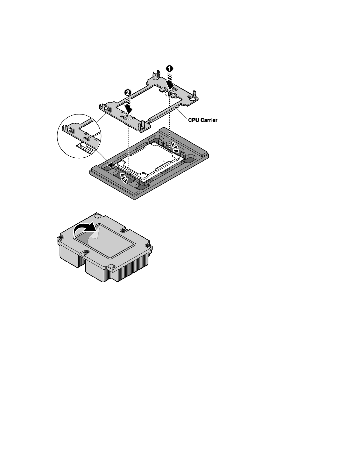
Installation 60
2. Align the marker (triangle) on the CPU carrier with the same marker located on the processor. The
protrusions on the CPU carrier are also aligned with the indentations on the processor when properly
aligned.
3. Press the CPU carrier to make sure it is locked with the processor.
4. Remove the TIM material protective film from the heat sink.

Installation 61
5. Locate the installation markers on the heat sink and the CPU carrier. Align the respective corners.
6. Press the heat sink to lock it onto the CPU carrier.
7. Remove the processor assembly from the processor tray.

Installation 62
8. Align the heat sink assembly over the CPU socket. Make sure the guide pins on the socket align with
the mounting holes on the CPU carrier.
9. Lower the heat sink assembly and install in the slot. The guide pins are inserted through the mounting
holes on the heat sink assembly when properly installed.
10. Tighten the four retaining screws clockwise, in the order shown, to secure the processor assembly.
11. Repeat the procedure for the additional processor.
12. Install the air baffle (on page 31).
13. Install the access panel (on page29).

Installation 63
System board modules
Removing a system board module
To remove a system board module:
1. Power off the server, and then detach all of the power cords from the power supplies.
2. Remove the access panel (on page 29).
3. Remove the system fan (on page 32).
4. Remove the air baffle (on page 30).
5. Remove the PCIe card (on page47) or the expander board (on page 50).
6. Remove the OCP mezzanine card (on page 53).
7. Remove the memory modules(on page 55).
8. Remove the processors(on page 56).
9. Disconnect the cables from the system board.
10. Release the thumb screws securing the system board to the chassis.
11. Hold the handles and slide the system board until the I/ O ports on the boardare clear of the slots on
the chassis.
12. Remove the system board.

Installation 64
Installing a system board module
To install a system board module:
1. Align the system board assembly in the chassis. Make sure the system board assembly is seated
correctly on all sides of the system board.
2. Use the handles to slide the system board towards the rear of the chassis and into the I/ O slots. The
I/ O ports are flush in the chassis slots when the system board is installed correctly.
3. Secure the system board to the chassis with the csrews, see the following figure.
4. Connect the cables to the system board.
5. Install the processors (on page59).
6. Install the memory modules (on page56).
7. Install the OCP mezzanine card (on page 54).
8. Install the PCIe card (on page48) or the expander board (on page 51).
9. Install the air baffle (on page 31).
10. Install the system fan (on page 34).
11. Install the access panel (on page 29).

Installation 65
Powering on and selecting boot options
1. Connect the Ethernet cable.
2. Press Power On/ Standby.
3. During the initial boot:
o To modify the BIOS default settings, press F2 or DEL when prompted from the start-up sequence to
enter the BIOS setup utility. By default, the BIOS setup utility runs in the English language.
o It is not necessary to modify the server configuration, press F7 during system boot to select the
boot device for system software installation.
o To enter PXE boot, pressF12 during boot time when prompted from the start sequence.
Installing the operating system
To operate properly, the server must have a supportedOS.
To install an OS on the server, use one of the following methods:
Local installation (USBkey or USB optical disc)
Remote deployment installation (PXE, virtual KVM)
Follow up install OS step and reboot system

Cabling 66
Cabling
Item
Description
Quantity
1
Front control signal cable
System board (J105) to front control board
2
HDD backplane power cable
System board (J76) to SATA backplane (J31)
3
HDD backplane SATA cable
System board (J14 and J15) to HDD backplane (J1 and J2)
4
M.2 adapter power cable 2
System board (J165) to M.2 adapter (J3)
Internal system cable routing
The server internal cable routing is listed in the following figure and table:
Routing for SKU1 (without PCIe card)

Cabling 67
Item
Description
Quantity
5
M.2 adapter power cable 1
System board (J166) to M.2 adapter (J3)
6
M.2 adapter SATA cable
System board (J41) to M.2 adapter (J2)
7
HDD backplane I2C cable
System board (J164) to SATA backplane (J3)
8
M.2 adapter SATA cable
System board (J40) to M.2 adapter (J2)
Item
Description
Quantity
1
Front control signal cable
System board (J105) to front control board
2
HDD backplane power cable
System board (J76) to SATA backplane (J31)
3
HBA SAS cable 2
PCIe card to HDD backplane (J1)
4
HBA SAS cable 1
PCIe card to HDD backplane (J2)
5
M.2 adapter power cable 2
System board (J165) to M.2 adapter (J3)
6
M.2 adapter power cable 1
System board (J166) to M.2 adapter (J3)
7
M.2 adapter SATA cable
System board (J41) to M.2 adapter (J2)
Routing for SKU1 (with PCIe card)

Cabling 68
Item
Description
Quantity
8
HDD backplane I2C cable
System board (J164) to SATA backplane (J3)
9
M.2 adapter SATA cable
System board (J40) to M.2 adapter (J2)
Item
Description
Quantity
1
Front control signal cable
System board (J105) to front control board
2
U.2 HDD backplane Slimline cable
System board (J90) to U.2 HDD backplane (J11)
3
Slimline x8 cable
Expander board (J1, J2 and J3) and system board (J45) to U.2 HD
backplane (J9, J10, J12 and J15)
4
HDD backplane power cable
System board (J76) to U.2 HDD backplane (J14)
5
M.2 adapter power cable 2
System board (J165) to M.2 adapter (J3)
6
M.2 adapter SATA cable
System board (J41) to M.2 adapter (J2)
Routing for SKU2
D

Configuration 69
Configuration
BMC
Web GUI introduction
The web GUI is a friendly interface for the end users. A user can access the iBMC FW via a web
browser, and then go through the server status and do many configurations to the IBMC FW.
The default user privilege is set to administrator. The web function access rights are determined by
different privileges. For example, the administrator privilege can access all functions, but the user privilege
cannot.
The web GUI provides many useful functions, such as:
firmware update
system power control
system event log (SEL)
current sensor reading
configuration for: BMC network, user accounts, serial, PEF, alerts, SOL, information about BMC, and
the system
IP address
Static and DHCP are the two common IP sources of iBMC FW. The default setting is DHCP. The detailed IP
address information is available from the BIOS setup menu.
User name and password
A user name and password are required to establish a web GUI session. The user should also have
accessibility to the LAN channel. Use the system management software toset the user name, password,
and grant access. The default setting is shown below:
ID 2: User Name = ADMIN Password = ADMIN
Web browsers
iBMC FW supports either Microsoft Internet Explorer(Windows platform) or Firefox (Linux platform).
The embedded web server provides full access. The web GUI is accessible via the HTTP protocol or via the
encrypted HTTPS protocol.
Logging in
To log in to the web GUI, enter the iBMC FW IP address into a web browser. An example of using the
HTTP protocol is http:/ / 10.141.104.176. An example of using the encrypted HTTPS protocol is
https:// 10.141.104.176

Configuration 70
Updating the firmware
Many common problems can be resolved by updating the firmware. The BMC FW can be updated
through a host-based utility or through the web GUI.
Restoring the default configuration
The BMC FW supports an OEM command to restore all of the configuration values to their defaults.
Using the OEM command restores all IPMI configuration parameters and all Linux user configuration
files (password, group, and so on). The OEM command is not available to the end user, but the web GUI
provides a friendly interface to do this. This command does not restore the SEL records.
BMC FW version
The " Get Device ID" command (NetFn Application, Command 1) reports the firmware revision. The
" Get Device ID" command also reports the auxiliary firmware revision.
The firmware build ID can map from the firmware revision. Naming convention of build ID is J2BTxxy. " xx"
is minor revision (BCD encoded), and" y" is auxiliary firmware revision. " y" is " a" if auxiliary firmware
revision is 0, and " y" is " b" if auxiliary firmware revision is 1, and so on. For example, if the firmware
revision is 0.12.0, the build ID is J2BT12A; if the firmware revision is 0.12.1, the build ID is J2BT12B.
End-users can confirm whether restore default configuration whenupdating firmware through the utilities or
through the web GUI.
The default configuration should be restored whenSDRis changed.
Updating BMC using Linux
To update BMC using Linux:
1. Log into Linux.
2. Open the terminal.
3. Create new directory " / work ", command:
mkdir /work
4. Copy the BMC FW package to the / work directory using the command:
cp file_name.zip /work
5. Change the directory using the / work, command:
cd /work
6. Uncompress the BMC FW package using the command:
upzip file_name.zip

Configuration 71
7. Enter directory of uncompressed before, command:
cd file_name/Linux/linux64bit/
8. Add execute permission for all of the files in thefile_name folder.
9. Execute /Update.sh to update BMC.
10. The following screen shot shows that BMC successfully updated.
Updating BMC via a web GUI
To update BMC using the web GUI:.
1. Log into the web GUI using a web browser.
2. Select Maintenance from the left tree view, and then click Firmware Update.
3. Choose the Preserve all configuration on the checkbox if all configurations need to be preserved.

Configuration 72
4. Select Firmware Image to select the BMC FW image.
5. Click Start Firmware Update.
6. Choose Flash selected section(Default is all) to start BMC FW update.

Configuration 73
7. After BMC FW is updated, system will pop up a message.
BIOS Menu
Description
Main
General product information including BIOS/ memory information, system language, and
time/ date
Advanced
Configuration information for the SMART settings, AST1250 super IO, network stack, CSM,
USB, serial port console redirection, PCI subsystem settings, and trusted computing
Platform
Configuration
Configuration information for the PCH, and server ME.
Socket
Configuration
Configuration information for the processor, common RefCode, UPI, memory, IIO, and
advanced power management.
Server Mgmt
BMC self-test status, BMC firmware version, timer settings and timeout behavior, system
event log setting, BMC network settings and view system event Log
Security
Set or change the user and supervisor passwords
Boot
Configure setup Prompt Timeout, bootup numlock state, quiet boot, boot mode select and th
boot device priority
Save & Exit
Save changes and exit, discard changes and exit, save changes and reset, discadr changes
and reset; save options: save changes, discard changes; Restore Defaults; Boot Override an
Launch Build-In EFI Shell
BIOS settings
There are eight menus in the BIOS setup utility, which appear in the following order: Main, Advanced,
Platform Configuration, Socket Configuration, Server Mgmt, Security, Boot, and Save & Exit. Use the arrow
keys to navigate the menus or options that are listed on the menu. Configurable menu options or fields
appear in color. For further instructions about how to navigate and change settings in the BIOS setup
utility, see the on-screen instructions that are provided on the menu.
BIOS setup menus
The following table provides descriptions for the top-level BIOS setup menus.

Configuration 74
POST error message
SMBIOS Event Log
Description
0x07
POST memory resize
0x08
POST errors
0x10
System limit exceeded
0x16
Log area reset
0x17
System boot
0xFF
End of log
0x80
IDE device failed
0x81
Flash device update operation failed
0x82
No more PCI resources available
0x83
No space for any more legacy OPROM
0x84
Invalid password entered three times
0x85
Clear CMOS
Sensor
Name
Sensor
Type
Sensor
Number
E/ R
Type
Event
Data1
Event
Data2
Event
Data3
Description
BIOS POST
Sensor
0x0F
0x09
0x6F
0xC0
0x01
0xFF
System firmware error. No system
memory is physically installed in
the system.
0x0F
0x6F
0xC0
0x02
0xFF
System firmware error. No usable
system memory, all installed
memory has experienced an
unrecoverable failure.
0x0F
0x6F
0xC0
0x0A
0xFF
System firmware error. No video
device detected.
0x07
0x6F
0x02
0xFF
0xFF
FRBI/ BIST failure.
0x10
0x6F
0x04
0xFF
0xFF
SEL full.
There are three methods to treat the event/ errors detected during POST:
Log to SMBIOS
Log to SEL
Shown on-screen during POST
SMBIOS event log
System event log (POST)

Configuration 75
Entering the pop-up boot menu
To enter the pop-up boot menu, pressF7 during system boot when the Press<F7> to enter Popup Boot
Menu message displays.
The pop-up boot menu screen displays as shown in the following figure.
Entering PXE boot
To access PXE boot:
1. Set Network as the first boot device in BIOS setup menu.
2. Select Network device from the pop-up boot menu.
Entering the BIOS setup menu
The BIOS setup menu is accessible using the following methods:
Connect a USB keyboard, mouse, and VGA monitor directly to the server.
Use a console (or terminal emulator connected to a computer) through the serial port on the rear
of the server.
To access the BIOS setup utility menus:
1. Press the power button on the front control panel to power up the server.
2. PressF2 or DEL during system boot when the Press <DEL> or <F2> to enter setup displays.
3. Use the left and right arrow keys to navigate the different menu options. When a menu option is
selected, the top-level screen for that option appears.
4. Use the up and down arrow keys to scroll up and down to select an item on a top- level screen.
When the up and down arrow keys are pressed, the only options that are highlighted are the
options that can be modified.
o If an item can be modified, user instructions for modifying the option appear in the right column of
the screen.
o If an item is a link to a sub-screen, a prompt to press Enter to access the sub-screen appears in the
right column.
5. Modify the setup item and pressF4 to save the changes and exit the screen.
6. Follow the instructions on the Save & Exit menu screen to save or discard your changes and exit the
BIOS setup utility.

Configuration 76
BIOS maintenance
This section provides information about upgrading the BIOS, clearing the BIOS password, clearing
CMOS, BIOS recovery, and a BIOS jumper description.
Upgrading the BIOS using DOS
The flash memory update utility loads a fresh copy of the BIOS into flash ROM. This utility only updates the
BIOS region.
BIOS update utility: AFUDOS.EXE
Boot the system to DOS environment and execute the following command to update BIOS:
AFUDOS <BIOS ROM File Name>[Option 1][Option 2]
or
AFUDOS<Output BIOS ROM File Name><Commands>
Commands
Use the mandatory field to select an operation mode.
o / O Save current ROM image to file
o / U Get and display ROM ID from BIOS ROM file
o / S Refer to Option: / S
o / D Verification test of given ROM File without flashing BIOS.
Options
Use the optional field to supply more information for flashing the BIOS ROM.The following lists the
supported optional parameters and format:
o / P Program main bios image
o / B Program Boot Block
o / N Program NVRAM
o / E Program Embedded Controller block if present
o / K Program all non-critical blocks
o / Kn Program n'th non-critical block only (0>= n <=7)
o / Q Quiet mode enable
o / REBOOT Reboot after update BIOS done
o / X Do not check ROM ID
o / S Display current system's BIOS ROM ID
o / R Preserve all SMBIOS structures during NVRAM programming.
o / Rn Preserve SMBIOS type N during Boot Block programming.
o / ECUF Update EC BIOS when newer version is detected.
o / Shutdown Shutdown after programming.
Rules
o Any parameter enclosed by <> is a mandatory field.
o Any parameter enclosed by [ ] is an optional field.
o <Commands> cannot co-exist with any [Options].

Configuration 77
o The main BIOS image is the default flashing area if no options are present.
Flash Command
Description
afudos XXXX.ROM / P
Program main BIOS image
afudos XXXX.ROM / P / B
Program main BIOS and BB (Boot Block)
afudos XXXX.ROM / P / B / N
Program main BIOS, BB and NVRAM
afudos XXXX.ROM / P / B / R
Program BB and main BIOS without SMBIOS
o [/ REBOOT], [/ X], and [/ S] automatically enables the [/ P] function automatically.
o If [/ B] is present alone, only the boot block area needs to be updated.
o If [/ N] is present alone, only the NVRAM area needs to be updated.
o If [/ E] is present alone, only the embedded controller block needs to be updated.
Clearing the BIOS password
If the user and/ or administrator password is lost or forgotten, clear both passwords by moving the
password clear jumper into the clear position.
The BIOS determines if the password clear jumper is in the clear position during BIOS POST and clears
any passwords if necessary. The password clear jumper must be restored to its original position for the
new password to remain set.
Clearing the CMOS
The CMOS clear jumper uses RTCRST# to:
Clear CMOS values
Set the RTC power well configuration bits to default.
To support legacy BIOS, CMOS can be cleared through the restore function to return the settings (stored in
NVRAM) to the default settings.
There are two methods to clear the CMOS:
Clear the CMOS jumper.
Remove the CMOS battery when the system is inAC OFFstatus.
Important: After clearing the CMOS, the BIOS setup default is restored, but the password that was set by
the user is still reserved.
Recovering the BIOS
If the BIOS image is corrupt, a system BIOS update fails, or the syste m fails to complete POSTth, e BIOS
must enter recovery mode. In recovery mode, an entire BIOS image can be refreshed to BIOS flash part.
To recover the BIOS:
1. Turn off the system power.
2. Open the chassis.
3. Move the BIOS recovery jumper from the normal positions 1-2 to the recovery positions 2-3.
4. Close the chassis.
5. Copy the latest BIOS image file (DC1F1XXX.ROM) to a USB drive, XXX is the revision number. A
bootable USB is not required.

Configuration 78
6. Insert the USB drive into the system.
Jumper
Description
Jumper Adjustment
J34
PASSWORD CLEAR
Clear password
J64
BIOS RECOVERY
BIOS recovery
J206
ME RECOVERY
ME recovery
J66
RTC RST
Clear CMOS
SW2
RST BTN
System reset
J81
INTRUDER
Chassis intruder
7. Power up the system.
8. The system display setup<Recovery> screen displays automatically and flash update automatically
runs.
9. Select Proceed with flash update. Flash update automatically runs.
10. Wait until <Program new data> completes, and then press Enter to shut down the system.
If the signature of FV_MAIN area is invalid, the BIOS automatically enters recovery mode; if this occurs,
only perform steps 5 through 10.
After recovery completes, if the recovery jumper forces the BIOS recovery turn off the system, and then
restore the jumper to its normal position.
BIOS jumpers
This section provides information about the BIOS. See the following table to locate the BIOS maintenance
jumpers.
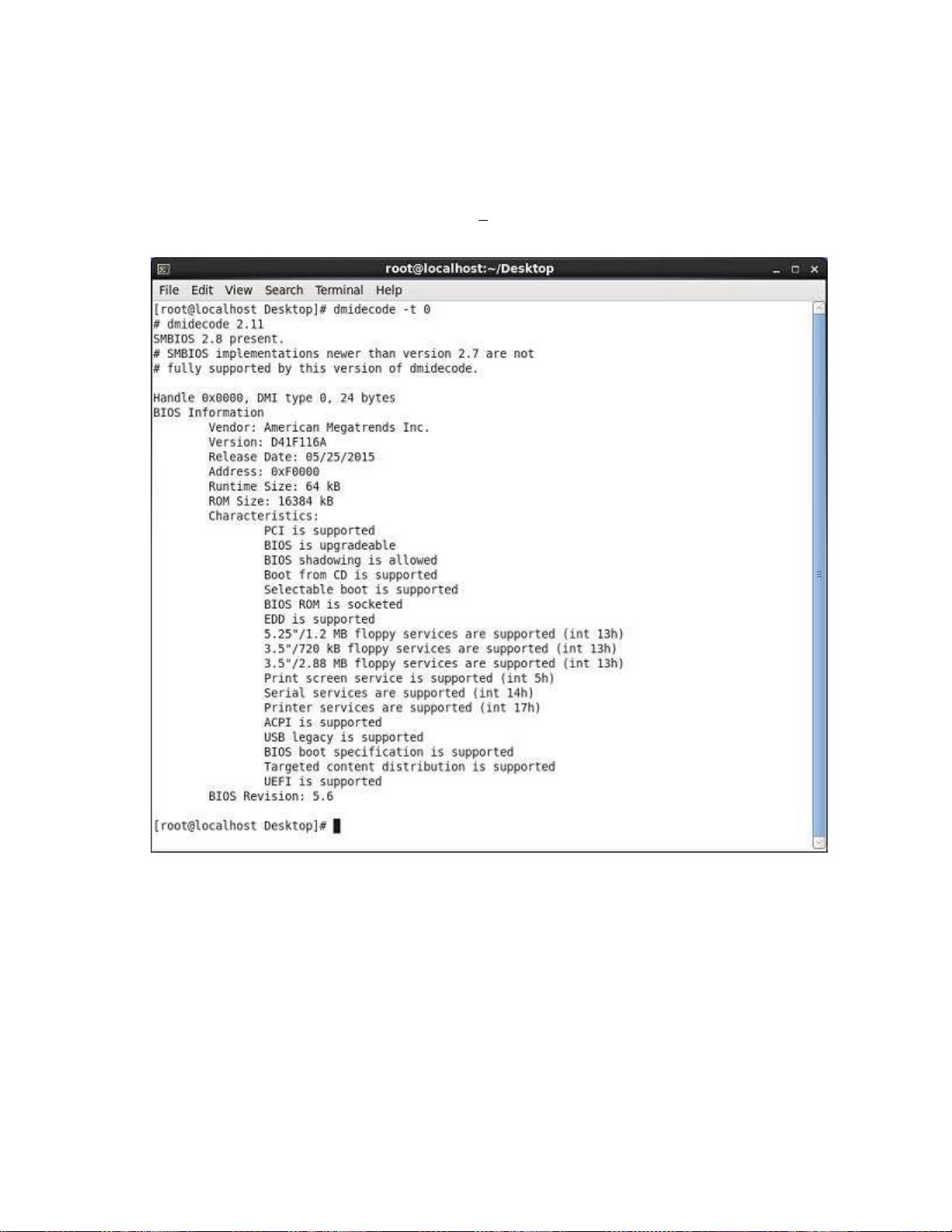
Configuration 79
Checking the FW version
Checking the BIOS version using Linux
1. Log into Linux.
2. Open the terminal. Execute the dmidecode t 0 command to display the BIOS version, as shown in
the following figure.

Configuration 80
Checking the BIOS version using the BIOS setup utility
1. Log into the BIOS setup utility.
2. Use the arrow keys to select theMain, menu to display the BIOS version as shown in the following
figure.
Checking the BMC version using Linux
1. Log into Linux.
2. Open the terminal. Execute theipmitool –I open mc info command to display the BMC version
as shown in the following figure.

Configuration 81
Checking the BMC version using the web GUI
1. Log into the web GUI.
2. Select Maintenance from the left tree view, and then click Firmware Information to display the BMC
version, as shown in the following figure.

Configuration 82
Checking the event log
Checking the system event log using Linux remote desktop
1. To check the system event log using Linux Log into Linux.
2. Open the terminal.
3. Execute the ipmitool -I lanplus –H BMCIP –A admin –P password sel list command
to check the system event log.
The system event log is shown in the following figure.

Configuration 83
Checking the system event log using the web GUI
To check the system event log usingthe web user interface:
1. Log into the web GUI.
2. Select Dashboard from the left tree view, and then click Firmware Information.
3. Click Details link on Today and 30 days to display the system event log.

Configuration 84
Checking the event log using the BIOS setup utility
System Event Logs
To check the eventlog using the BIOS setup utility:
1. Enter the BIOS setup utility, and then select theServer Mgmt menu.
2. Use the arrow keys to select View System Event Log, and then press Enter. The " System Event Log"
displays.

Diagrams 85
Diagrams
System board diagram

Spare parts catalog 86
Spare parts catalog
Customer self repair
TradeDX products are designed with many Customer Self Repair (CSR) parts to minimize repair time and
allow for greater flexibility in performing defective parts replacement. If during the diagnosis period
TradeDX (or TradeDX service providers or service partners) identifies that the repair can be accomplished
by the use of a CSR part, TradeDX will ship that part directly to you for replacement. There are two
categories of CSR parts:
Mandatory Parts for which customer sel-frepair is mandatory. If you request TradeDX to replace
these parts, you will be charged for the travel and labor costs of this service.
Optional Parts for which customer self-repair is optional. These parts are alsodesigned for customer
self-repair. If, however, you require that TradeDX replace them for you, there may or may not be
additional charges, depending on the type of warranty service designated for your product.
Important: Some manufacturer parts are not designed for customer self-repair. In order to satisfy the
customer warranty, TradeDX requires that an authorized service provider replace the part.These parts are
identified as " No" in the Illustrated Parts Catalog.
Based on availability and where geography permits, CSR parts will be shipped for next business day
delivery. Same day or four-hour delivery may be offered at an additional charge where geography permits.
If assistance is required, you can call the Technical Support Center and a technician with help you over
the telephone. TradeDX will specify if a defective part must be returned to TradeDX. In cases where it is
required to return the defective part to TradeDX, you must ship the defective part back to TradeDX within a
defined period of time, normally five (5) business days. The defective part must be returned with the
associated documentation in the provided shipping material. Failure to return the defective part may result
in TradeDX billing you for the replacement. With a customer self-repair, TradeDX will pay all shipping and
part return costs and determine the courier/carrier to be used.
Parts only warranty service
Your Limited Warranty may include a parts only warranty service. Under the terms of parts only warranty
service, TradeDX will provide replacement parts free of charge.
For parts only warranty service, CSR part replacement is mandatory. If you request TradeDX to replace
these parts, you will be charged for the travel and labor costs of this service.

Spare parts catalog 87
Replaceable components
Item
Description
Spare Part Number
Customer Self Repair
1
Mandatory Parts for which customer self repair is mandatory. If you request TradeDX to replace these parts, you
will be charged for the travel and labor costs of this service.
2
Optional Parts for which customer self repair is optional. These parts are also designed for customer self repair.
If, however, you require that TradeDX replace them for you, there may or may not be additional charges, depending
on the type of warranty service designated for your product.
3
No Some parts are not designed for customer self repair. In order to satisfy the customer warranty, TradeDX
requires that an authorized service provider replace the part. These parts are identified as" No" in CSR.

Troubleshooting 88
Troubleshooting
Troubleshooting preparation
Pre-diagnostic
WARNING: To avoid potential problems, ALWAYS read the warnings and cautionary
information in the server documentation before removing, replacing, reseating or modifying
system components.
Important: Refer to the server documentation for information on procedures, hardware options, software
tools and operating systems supported by the server.
Follow the following pre-diagnostic steps before system troubleshooting process:
1. Review the important safety information.
2. Collect symptom information.
3. Prepare the server for troubleshooting.
4. Use the troubleshooting flowchart to begin the troubleshooting proces.s
Symptom collection
Before troubleshooting a server problem, collect the following information:
Does the server power on?
Does the server complete POST?
If not, then what do the health LEDs indicate? Is video display available? If the server completes POST
and video is available, are there any POST error messages?
Record the text of the POST error message as displayed.
Does the server successfully boot an operating system or hypervisor? If not, does the server display
any of the following symptoms?
o An uncorrectable machine check exception
o Stop error or blue screen (Windows)
o Purple diagnostic screen (Linux)
o Linux kernel panic
o A system" hang"
o A system" freeze"
If the problem occurs after an OS is installed:
o Does the problem occur when a new application is loading or a patch is applying?
o What symptoms did the server display when the server malfunctioned? (for example, did it reboot,
were there LED codes, health logs, messages on the screen, and so forth)

Troubleshooting 89
Are any indications present that show that the malfunction was reported as a memory error, PCI error,
or so forth? The processor now contains the memory controller and PCI Express controller, so faults in
other areas may be attributed to a processor malfunction.
When did the problem occur?
Record exactly when the problem happens (include the date and time).If it happens more than once, keep
a list of all symptoms for each occurrence.
What events preceded the failure?
After which steps does the problem occur?
What has been changed since the time the server was working?
Did you recently add or remove hardware or software?
How long has the server exhibited problem symptoms?
If the problem occurs randomly, what is the duration or frequency?
Observe the server LEDs and their statuses. See the LED Indicators for more information.
Prepare the server for diagnosis
1. Be sure that the server is in the proper operating environment with adequate power, air conditioning,
and humidity control. For required environmental conditions, see the server documentation.
2. Record any error messages displayed by the system.
3. Remove all external peripherals such as the network cables, monitor, keyboard, and mouse.
4. Collect all tools and utilities necessary to troubleshoot the problem, such as a Torx
screwdriver, loopback adapters, ESD wrist strap, and software utilities.
5. Determine if the server will troubleshoot offline or online.
6. To diagnose the server offline, power down the server and peripheral devices. If possible, always
perform an orderly shutdown:
a. Exit any applications.
b. Exit the operating system.
c. Power down the server.
7. Disconnect any peripheral devices not required for testing (any devices not necessary to power up the
server).
Performing processor procedures in the troubleshooting process
Before performing any troubleshooting steps that involve processors, review the following guidelines:
Be sure that only authorized personnel perform the troubleshooting steps that involve installation,
removal, or replacement of a processor.
Never touch the contacts in the processor socket. THE PINS ON THE SYSTEM BOARD ARE VERY
FRAGILE AND EASILY DAMAGED. If the contacts inside the processor socket are damaged, you
must replace the system board.
Some processor models require the use of a processor installation tool, and specific steps are
documented to ensure that they do not damage the processor or processor socket on the system
board. For server models that have pins inside the processor socket, remember tha t THE PINS ON THE

Troubleshooting 90
SYSTEM BOARD ARE VERY FRAGILE AND EASILY DAMAGED. If t.he socket is damaged, you must
replace the system board.
Always complete all other troubleshooting procedures before removing or replacing a processor.
Breaking the server down to the minimum hardware
configuration
During the troubleshooting process, it might be necessary to break down the server to the minimum
hardware configuration. A minimum configuration consists of only the components needed to boot the
server and successfully pass POST.
When requested to break the server down to the minimum configuration, uninstall the following
components, if installed:
All additional DIMMs
Leave only the minimum required to boot the server either one DIMM or a pair of DIMMs.
All additional cooling fans, if applicable
All additional power supplies, if applicable (leave one installed)
All hard drives
All optional mezzanine cards
All expansion boards
Before removing the components, be sure to determine the minimum configuration for each component and
follow all guidelines in the server user and maintenance guide.
Always use the recommended minimum configuration above before removing any processors. If you are
unable to isolate the issue with the configuration above,you will then remove all but one of the processors.
CAUTION: Before removing or replacing any processors, be sure to follow the guidelines
provided in removing and installing processors steps.
Failure to follow the recommended guidelines can cause damage to the system board, requiring
replacement of the system board.

Diagnostic flowcharts 91
Diagnostic flowcharts
Troubleshooting flowcharts
To effectively troubleshoot a problem, TradeDX recommends that you start with the first flowchart in this
section, " Start diagnosis flowchart (on page 92)" and follow the appropriate diagnostic path. If the other
flowcharts do not provide a troubleshooting solution, follow the diagnostic steps in "General diag nosis
flowchart (on page 96)".
The General diagnosis flowchart is a generic troubleshooting process to be used when the problem is not
server-specific or is not easily categorized into the other flowcharts.
The available flowcharts include:
Start diagnosis flowchart
Remote diagnosis flowchart
General diagnosis flowchart
Power-on problems flowchart
POST problems flowchart
Operating system boot problems flowchart
Some information provided in the flowcharts can be further explained in othersections of this document.

Diagnostic flowcharts 92
Start diagnosis flowchart
Diagnosis
Yes
NO
Diagnosis
Yes
NO
problems
NO Yes
NO
Yes
Problems
NO Yes
Use the following flowchart to start the diagnostic process.

Diagnostic flowcharts 93
Start Remote
BMC,
remote Desktop
services
RDS
Yes
Does the
condition still exist?
No
Does the
condition still exist?
No
End
to Troubleshoot
Remote diagnosis flowchart
OS system log and
The Remote diagnosis flowchart provides a generic approach to troubleshoot a server from a remote
location.
Download
BMC log
Yes
BMC
Use BMC
the server
Use the Onboard
Administrator to
Troubleshoot the
server

Diagnostic flowcharts 94
General diagnosis flowchart
The General diagnosis flowchart provides a generic approach to troubleshooting. If you are unsure of the
problem, or if the other flowcharts do not fix the problem, use the following flowchart.

Diagnostic flowcharts 95
What color is
The system
power LED?
Is the system
power LED flashing green or
solid green?
Is the power
Source operating
properly?
What color is Green
The system
health LED?
Does condition
still exIst?
Contact
Support
Are any
Co SID
mponent
LED illuminated?
If condition persists
Replace the power
Replace the power
loose power cables
Power-on problems flowchart
No
If condition persists
Replace component
Symptoms:
The server does not power on.
The system power LED is off or flashing.
The health LED is solid orange.
Possible causes:
Improperly seated faulty power supply
Loose or faulty power cord
Power source problem
Improperly seated component or interlock problem
Start Power-on
Problems
Check for
Press the power
On/Standby button
And wait 45seconds
Disconnect the
Power cable, remove
And then reinstall the
power supply
supply
source
Replace
component

Diagnostic flowcharts 96
operating?
No
yes
yes
No
POST problems flowchart
Yes
No
yes No
yes
troubleshooting
Yes
yes
No
No
Yes
Yes No
Symptoms:
Server does not complete POST
Server completes POST with errors
Troubleshooting
No
Yes

Diagnostic flowcharts 97
Operating system boot problems flowchart
Start OS boot
problems
Does the boot
Device cannot
be detected?
Does the crash,
blue boot
screen , Auto re
And some error info
symptom exist?
Reboot and
Enter The safe Mode
Successfully?
Does the
Condition still exist?
Does the
Condition still exist?
Does the
Condition still exist?
Does the
Condition still exist?
Does
the condition
still exist?
Does
the condition still
exist?
Does
the Condition
still exist?
End
Configuration to isolate
server spare parts
See the SAS RAID card and
hard Drive documentations
And to be sure is matched
operation system
Repair the OS configuration files
Scan for viruses with an updated
record relevant log
Driver compatibility issues
Device correctly in
Information on the repair tag
Sending back a failed part.
available: OS log And
Possible Causes:
Corrupted OS
Hard drive subsystem problem
Incorrect boot order setting in the BIOS
Hardware problem
Reset the boot
BIOS
Check for loose
Data cable and
Power supply
Cable and so on
Reinstall the
Corrupted OS
The virus
Update correct drives
virus scan utility
the server
Troubleshoot or
replace basic
Record symptom and error
Add one part at a
Time back to
faulty component.
Ensure the
following Information is
BMC log
Break server down
To minimal
configuration
Contact
Support
Isolate and minimize the
Memory configuration
Record action
taken

Diagnostic flowcharts 98
Troubleshooting general problems
Resolving common problems
Common problem guideline
1. System cannot power on
o Be sure that all power and I/ O cords are securely connected.
o Verify that the system board is powered up.
o Configure the server with the minimum components (one CPU, the least amount of memory, and
connect only the display monitor and keyboard). Connect directly to the system board jumper to
determine if the server now starts normally.
o Check the power. Remove all of the power cables. Connect the green cable and the black cable
on the PSU power to check the resul.t
o If problems continue to occur, remove and reinstall each device, checking the connectors and
sockets for bent pins or other damage.
2. System frequently reboots
There are generally three factors that might cause the system to reboot:
o Breakdown of power
Supply power to the server from an available power source.
o Problems with memory
Check the event log or memory configuration from the BIOS to determine if there is a problem
with the memory which requires replacing the memory. Check the display to determine if the
memory error was detected during POST. If the event log shows that a memory error caused the
memory problem, re-seat all of the memory by removing and re-installing all of the memory
modules. If reseating the memory modules does not resolve the memory/ reboot problem, replace
the memory.
o Problems with the software
Update the software or re-install the system.
3. System stopped issue
Track the reason sthe system stopped from the software and hardware, respectively.
o Software tracking: Check the system event log to identify and locate the problem.
o Hardware tracking: The power supply is not sufficient; HDD/ SSDhas some problem (scan the
surface of them to check). Addon cards might also cause the system to halt (for example,
SCSI/ RAID cards or other PCI facilities).
Pay attention to any possible reasons any of the hardware components might have caused the
system to stop, even if the problem has been resolved. Observe the server to confirm that the system
stop issue has whether it has been thoroughly resolved.
4. Failure to recognize the HDD during system installation
o Determine if the HDDs were installed in the HDD carriers.
o Determine if the SAS/ SATA cables are correctly connected.
o Check the HDD LED indicators to determine if the drives are receiving power.

Diagnostic flowcharts 99
o Determine if the storage controller driver is properly installed or the driver is not compatible with
the HDD.
o Determine if the driver is compatible with the HDD.
Handling and installing the CPU
CAUTION: Failure to properly handle the CPU can cause damage to CPU components and the
system board connector. It can also cause the systemto collapse.
When handling a CPU, observe the following guidelines:
Before installing the CPU, determine if the CPU has bent pins
Be careful not to touch the CPU pins
When installing the CPU, remember to place the side with triangle point onto the triangle on the
board
Correctly installing the CPU is not enough. You must also consider the heat radiation; if the CPU
temperature is too high, it might affect the system performance. The heat sink is used for the CPU
heat radiation. When you install heat sink, observe the following guidelines:
When you install the heat sink:
o Align the heat sink so the sticker label faces the memory module
o Secure the heatsink with the screw
DIMM handling and installation guidelines
CAUTION: Failure to properly handle DIMMs can cause damage to DIMM components and
the system board connector.
DIMM population order and configuration is critical in maximizing performance for the system.
When handling a DIMM, observe the following guidelines:
Avoid electrostatic discharge.
Always hold DIMMs by the side edges only.
Avoid touching the connectors on the bottom of the DIMM.
Never wrap your fingers around a DIMM.
Avoid touching the components on the sides of the DIMM.
Never bend or flex the DIMM.
When installing a DIMM, observe the following guidelines:
Before seating the DIMM, open the DIMM slot and align the DIMM with the slot. Some servers require
the use of a DIMM tool to open the slots.
To align and seat the DIMM, use two fingers to hold the DIMM along the side edges.
To seat the DIMM, use two fingers to apply gentle pressure along the top of the DIMM.

Diagnostic flowcharts 100
SAS/ SATA and SSD drive guidelines
When adding drives to the server, observe the following general guidelines:
Drives must be the same capacity to provide the greatest storage space efficiency when drives are
grouped together into the same drive array.
Drives in the same logical volume must be of the same type.
Hardware problem troubleshooting
Power problems
Power source problems
1. Press the Power On/ Standby button to be sure it is on. If the server has a Power On/ Standby button
that returns to its original position after being pressed, be sure you press the switch firmly.
2. Plug another device into the grounded power outlet to be sure the outlet works. Also, be sure the
power source meets applicable standards.
3. Replace the power cord with a known functional power cord to be sure it is not faulty.
4. Replace the power strip with a known functional power strip to be sure it is not faulty.
5. Have a qualified electrician check the line voltage to be sure it meets the required specifications.
6. If Enclosure Dynamic Power Capping or Enclosure Power Limit is enabled on supported servers, be
sure there is sufficient power allocation to support the server.
7. Be sure no loose connections exist.
Power supply problems
1. Be sure no loose connections exist.
2. If the power supplies have LEDs, be sure they indicate that each power supply is working properly. If
the LEDs indicate a problem with a power supply(6.7Hz flashes green for 650W fixed PSU, yellow is
on for 800W or 500W RDN PSU), then check the power source. If the power source is working
properly, then replace the power supply.
If the 6.7Hz green LED is flashing for 650W fixed PSU, yellow LED is on for 800W or 500W RDN
PSU, it could mean any of the following:
o AC power unavailable
o Power supply failed
 Loading...