

Page 1
HDTV Converter Owner’s Manual
HDTV Converter
for DIRECTV®Service
Page 2

2007, KVH Industries, Inc. KVH and TracVision are registered trademarks of KVH Industries, Inc.
DIRECTV is a registered trademark of DIRECTV, Inc.
KU_HD_OM_CoverBW_3.07
HDTV Converter for DIRECTV®Service
flip here to view
quick reference guide
Page 3
OR OR
TriSat - Manual
Tracking 101
119 Menu 110
Set Sat Select Mode?
Yes Next Return
Auto or Manual?
Auto Manual Return
DualSat
Tracking <SAT NAME>
<SAT A> Menu <SAT B>
Return to "Set Sat Select Mode"
or "Install Satellite"
2005-2007, KVH Industries, Inc.
Select SAT 101 and:
119 110 Return
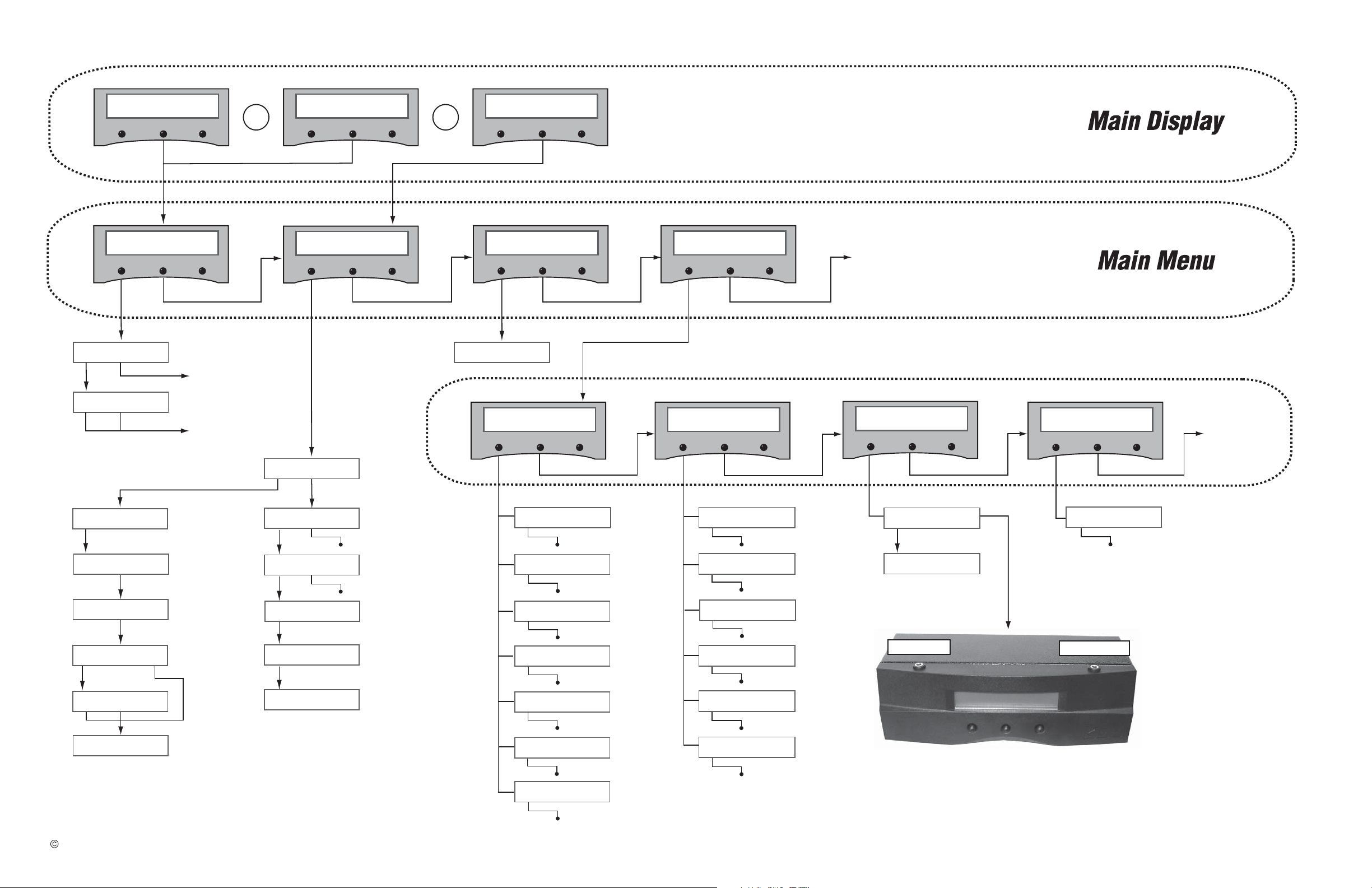
MultiSat Control Panel Menu Quick Reference Guide
MultiSat Control Panel Menu Quick Reference Guide
USA or Europe?
USA Europe Return
Installing TriSat
Group - Please Wait
101, 119, and 110
sats installed
Restarting antenna
Select Satellite A
Select Satellite B
Set Sat Select Mode
Auto Manual
Go to
TriSat - Manual
Main Display
Go to
TriSat - Automatic
Main Display
Select SAT 101 and:
119 110 Return
* Press any button to return
RF Flash Port
Main Flash Port
Use the latest version of the KVH Flash
Update Wizard to upgrade the software
Set brightness?
Yes Next Return
Control antenna?
Yes Next Return
Get antenna status?
Yes Next Return
Upgrade software?
Yes Next Return
Return to
"Get Antenna
Status"
Sleep Mode On/Off
Set sleep on/off?
Yes Next Return
Update Frequency Data
‡
Sat frequency scan?
Yes Next Return
Man control antenna?
Yes Next Return
Adjust Azimuth/Elevation
Configure Satellite?
Yes Next Return
Set Frequency, Symbol Rate,
FEC Code, and Network ID
‡
Set Latitude/Longitude
Set Lat/Long?
Yes Next Return
Current State *
Get State?
Yes Next Return
Bit Error Rate *
Get bit error rate?
Yes Next Return
Get System Errors?
Yes Next Return
Errors Detected *
Antenna Software Versions *
Get version?
Yes Next Return
Antenna Serial Number *
Get serial number?
Yes Next Return
Threshold and Signal Levels *
Get thres/sig level?
Yes Next Return
LNB Skew Angle *
Get skew angle?
Yes Next Return
Min Bright Max
*************
Set Display Brightness
^RF Use Jack Main^
HALT Return
System Halted
Set Instant On Mode On/Off
Set instant on/off?
Yes Next Return
Install A <Sat Name>
Yes Next Cancel
Install B <Sat Name>
Yes Next Cancel
Installing sats
Please Wait
<SatA> and
<SatB> installed
Restarting antenna
Trisat Mode?
Yes No Return
Antenna restarted
Install Satellite?
Yes Next Return
Restart Antenna?
Yes Next Return
Operations mode?
Yes Next Return
‡
TracVision M5/M7/M9 only
119 Menu
TriSat - Automatic
101-110: Tracking 101
Page 4
MultiSat Control Panel Owner’s Manual
MultiSat Control
Panel
With HDTV Converter
Owner’s Manual
This manual provides all of the basic information you need to
install, operate, set up, and troubleshoot the MultiSat Control
Panel (MCP) and HDTV converter.
NOTE: The MultiSat Control Panel is not a standalone unit. It is an
add-on accessory for an installed DVB-compatible TracVision
satellite TV antenna system.
Please direct questions, comments, or suggestions to:
KVH Industries, Inc.
50 Enterprise Center
Middletown, RI 02842-5279 USA
Tel: +1 401 847-3327
Fax: +1 401 849-0045
E-mail: info@kvh.com
Internet: www.kvh.com
MultiSat Control Panel
Serial Number
If you have any comments regarding this manual, please e-mail
them to manuals@kvh.com. Your input is greatly appreciated!
KVH Part # 54-0260 Rev. C
© 2007 KVH Industries, Inc., All rights reserved.
Page 5

TracVision and KVH are registered trademarks of KVH Industries, Inc.
The unique light-colored dome with contrasting baseplate is a registered trademark of KVH Industries, Inc.
DVB (Digital Video Broadcasting) is a registered trademark of the DVB Project.
DIRECTV is an official trademark of DIRECTV, Inc.
All other trademarks are the property of their respective owners.
Page 6

MultiSat Control Panel Owner’s Manual
Table of Contents
1Introduction
Using this Manual..............................................................................3
Product Overview ..............................................................................5
2 Installation
Inspecting Parts and Getting Tools....................................................9
Planning the Installation..................................................................10
Table of Contents
Preparing the MCP Mounting Site (Flush Mount only).....................11
Attaching the MCP Flush Mount Bracket
(Flush Mount only) ...........................................................................12
Wiring the MCP to the Antenna - R4/R5 Switchplate.......................13
Wiring the MCP to the Antenna - M5/M7 Switchplate.....................16
Wiring the MCP to the Antenna - M5/M7 GyroTrac..........................19
Wiring the MCP to the Antenna - M9 ............................................... 21
Wiring the HDTV Converter and Receiver ........................................23
Mounting the MCP ........................................................................... 25
Selecting the DIRECTV TriSat Group ................................................ 27
Choosing a Sat Select Mode............................................................29
Configuring the DIRECTV HD Receiver.............................................31
3Operation
Downloading the Program Guide to the Receiver............................35
Switching Satellites - TriSat............................................................36
Switching Satellites - DualSat.........................................................38
Accessing the Menu ........................................................................39
i
Page 7

MultiSat Control Panel Owner’s Manual
Table of Contents
4 Menu Functions
Adjusting Display Brightness ...........................................................43
Selecting Satellites to Track - TriSat ...............................................44
Choosing a Sat Select Mode - TriSat Only .......................................45
Selecting Satellites to Track - DualSat ............................................46
Manually Entering Latitude and Longitude ......................................47
Changing the Sleep Mode Setting....................................................48
Changing the Instant On Mode Setting ............................................49
Restarting the Antenna ....................................................................50
Viewing Antenna Status...................................................................51
Manually Controlling the Antenna....................................................53
Updating Satellite Frequency Data ..................................................54
Configuring Satellite Settings ..........................................................56
Upgrading Software.........................................................................57
5 Troubleshooting
Five Simple Checks..........................................................................61
Technical Support............................................................................62
Field Replaceable Units ...................................................................63
A Computer Diagnostics
Connecting a Laptop PC to the Main Flash Port...............................67
ii
Page 8

MultiSat Control Panel Owner’s Manual
B Wiring Diagrams
Wiring 1 HD Receiver - R4/R5 Configuration ................................... 71
Wiring 2 or More HD Receivers - R4/R5 Configuration....................72
Wiring 1 HD Receiver - M5/M7 Switchplate Configuration..............73
Wiring 2 or More HD Receivers - M5/M7 Switchplate
Configuration ...................................................................................74
Wiring 1 HD Receiver - M5/M7 GyroTrac Configuration ..................75
Wiring 2 or More HD Receivers - M5/M7 GyroTrac
Configuration ...................................................................................76
Wiring 1 HD Receiver - M9 Configuration........................................77
Wiring 2 or More HD Receivers - M9 Configuration......................... 78
Table of Contents
MCP Flush Mounting Template ............................................... 79
iii
Page 9

1. Introduction
This chapter provides a basic overview of this manual and your MultiSat
Control Panel with HDTV converter.
Contents
Using this Manual.............................................................. 3
Product Overview .............................................................. 5
MultiSat Control Panel Owner’s Manual
Chapter 1 - Introduction
1
Page 10
Using this Manual
This manual provides complete installation, operation, setup, and
troubleshooting information for your MultiSat Control Panel (MCP)
and HDTV converter.
Who Should Use This Manual
The installer should refer to the “Installation” chapter and “Wiring
Diagrams” appendix for information on installing the MCP and HDTV
converter.
The user should refer to the “Operation” and “Menu Functions”
chapters to learn how to operate and set up the control panel.
The user or servicing technician should refer to the
“Troubleshooting” chapter to help identify the cause of a system
problem.
MultiSat Control Panel Owner’s Manual
Chapter 1 - Introduction
Notifications Used in this Manual
This manual uses the following notifications to call attention to
important information:
This is a danger, warning, or caution notice. Be sure to read
these carefully to avoid injury!
IMPORTANT!
This is an important notice. Be sure to read these carefully to
ensure proper operation and configuration of your system.
NOTE: This is a Note that provides useful supplemental information.
TIP: This is a Tip that provides hints to get the most out of your system.
CAUTION
3
Page 11
MultiSat Control Panel Owner’s Manual
Chapter 1 - Introduction
Typographical Conventions
This manual uses the following typographical conventions:
Text Example Description
<Sat Name>
###
“System Overview” on
page 5
MCP Interface Conventions
When instructions indicate to select a specific MCP menu option, press
the button located directly beneath the menu option on the MCP
display.
Figure 1-1 Example of MCP Menu Option and Corresponding Button
101-110:Tracking 110
119 Menu
Text in brackets or the pound sign (#)
indicates a variable field on the MCP
display
Cross-reference to another chapter in
the manual or to a website
MCP
Related Documentation
In addition to this Owner’s Manual, the following documents are
provided with the product:
Document Description
Product Registration Form Details on registering the product
Warranty Statement Warranty terms and conditions
Contents List List of every part supplied in the kit
4
Page 12
Product Overview
The MultiSat Control Panel (MCP) and HDTV converter enable your
TracVision antenna to receive HDTV programming from DIRECTV’s
specially configured 110 satellite, in addition to DIRECTV’s 101 and
119 satellites.
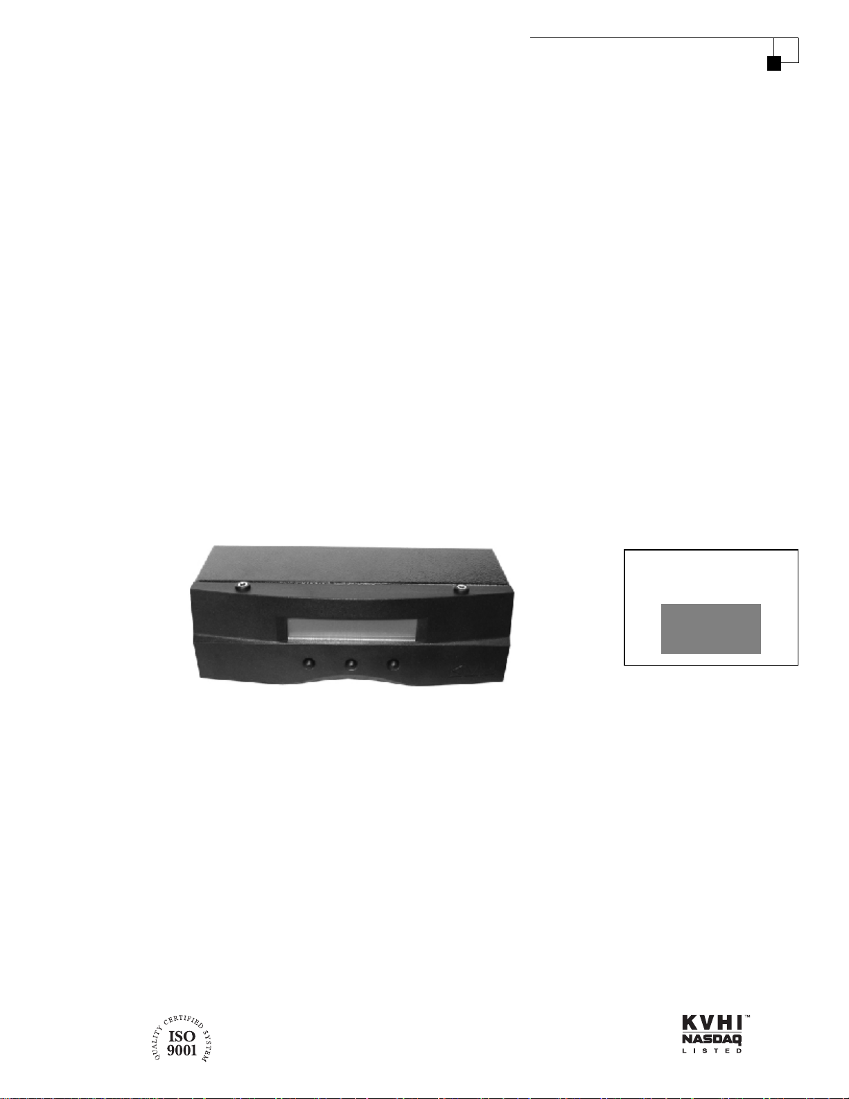
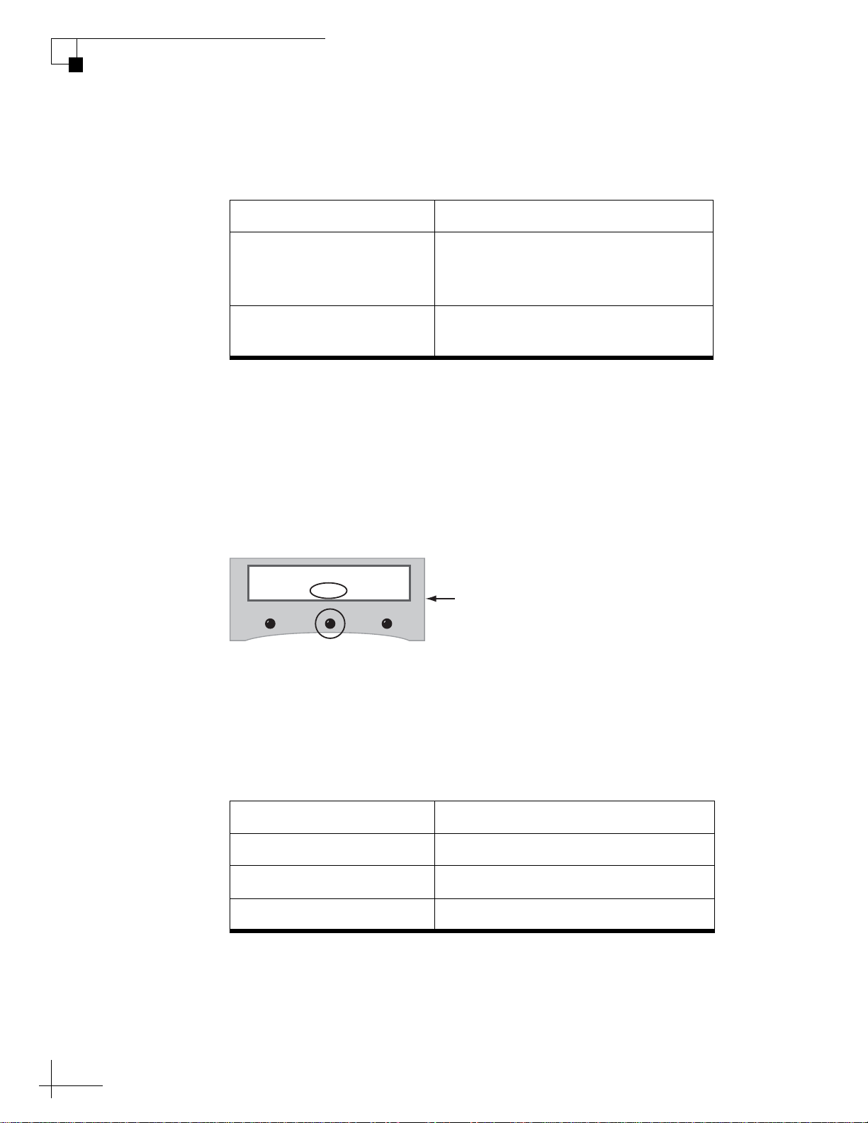
MultiSat Control Panel (MCP)
The MultiSat Control Panel (MCP) allows you to control the
TracVision antenna through a simple user interface consisting of an
LCD and three buttons (see Figure 1-2). Now you can easily configure
the antenna, select satellites, check system status, and restart the
antenna right from the MCP.
Figure 1-2 MCP Front Panel
MultiSat Control Panel Owner’s Manual
Chapter 1 - Introduction
LCD
Buttons
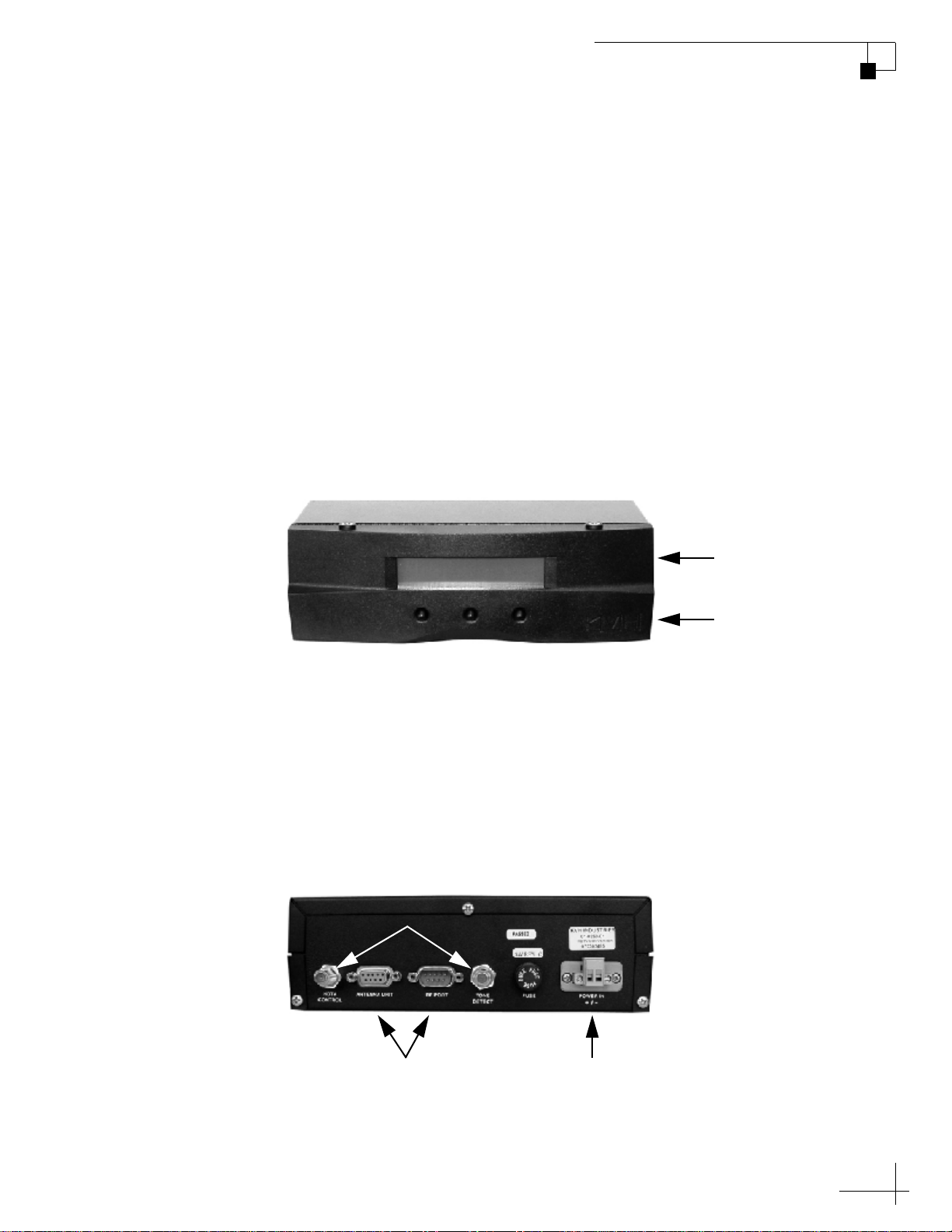
The MCP connects to your TracVision system via two data cables (see
Figure 1-3). The MCP also connects to the HDTV converter and
primary receiver to provide the HDTV control signal, as required, to
switch to the DIRECTV 110 satellite. Complete installation instructions
are provided in the next chapter. System wiring diagrams for each
antenna/receiver configuration are provided in “Appendix B” on
page 69.
Figure 1-3 MCP Rear Panel
HDTV Connections
TracVision Data Connections DC Power In
5
Page 13

MultiSat Control Panel Owner’s Manual
Chapter 1 - Introduction
HDTV Converter
The HDTV converter adjusts the signal frequency of DIRECTV’s 110
satellite, allowing the TracVision system to receive its high-definition
channels.
Figure 1-4 HDTV Converter
6
Page 14

2. Installation
This chapter explains how to connect the MCP and HDTV converter to
your TracVision system and how to mount the MCP.
IMPORTANT!
This manual assumes that you are adding the MCP to a TracVision
system that is already installed on the vessel/vehicle. If the antenna is
not yet installed, follow the detailed instructions in the antenna’s
manual to install and test the antenna system. Then follow the
instructions in this chapter to install the MCP and HDTV converter.
MultiSat Control Panel Owner’s Manual
Chapter 2 - Installation
Contents
Inspecting Parts and Getting Tools.................................... 9
Planning the Installation.................................................. 10
Preparing the MCP Mounting Site (Flush Mount only)..... 11
Attaching the MCP Flush Mount Bracket
(Flush Mount only)........................................................... 12
Wiring the MCP to the Antenna -
R4/R5 Switchplate........................................................... 13
Wiring the MCP to the Antenna -
M5/M7 Switchplate ......................................................... 16
Wiring the MCP to the Antenna -
M5/M7 GyroTrac.............................................................. 19
Wiring the MCP to the Antenna - M9 ............................... 21
Wiring the HDTV Converter and Receiver ........................ 23
Mounting the MCP ........................................................... 25
Selecting the DIRECTV TriSat Group................................ 27
Choosing a Sat Select Mode............................................ 29
Configuring the DIRECTV HD Receiver............................. 31
7
Page 15
Inspecting Parts and Getting Tools
Before you begin, follow these steps to make sure you have everything
you need to complete the installation.
1. Unpack the box and ensure it contains everything
shown on the Kitpack Contents List. Save the packaging
for future use.
2. Carefully examine all of the supplied parts to ensure
nothing was damaged in shipment.
3. Gather all of the tools and materials listed below. You
will need these items to complete the installation.
• Flat-head and Phillips-head screwdrivers
• 7/16" open-end wrench
MultiSat Control Panel Owner’s Manual
Chapter 2 - Installation
• Electric drill
• #29 and 3/32" drill bits
• 3/16" nut driver/socket
• Light hammer and center punch
• Adhesive tape
• Scriber or pencil
• DIRECTV HD receiver and HDTV television (required
to receive DIRECTV’s HDTV programming)
• Power cable for connecting power to the MCP from the
TracVision system (see Figure 2-1)
Figure 2-1 Power Cable Guidelines
Cable Length Use Cable Gauge
< 40 ft (12 m)
40-70 ft (12-21 m)
14AWG (2.5mm
12AWG (4mm
2
)
2
)
9
Page 16

MultiSat Control Panel Owner’s Manual
Chapter 2 - Installation
Planning the Installation
Before you begin, consider the following MCP installation guidelines.
• Select an MCP mounting location in a dry, well-ventilated area
inside the vessel/vehicle away from any heat sources or salt spray.
• Be sure the MCP’s front panel will be easily accessible to the user.
The owner will use the MCP’s buttons to control the antenna.
• Be sure to leave enough room at the MCP’s rear panel for
connecting the cables (see Figure 2-2 for MCP dimensions).
Figure 2-2 MCP Dimensions
0.66"
(16.7 mm)
3.17"
(80.6 mm)
2.52"
(64.1 mm)
8.1"
(205.7 mm)
• Since the supplied main control cable and RF control cable are both
25 ft (7.6 m) long, the MCP must be located within 25 ft (7.6 m) of
the TracVision antenna’s switchplate, ADCU, or MCU. You will
need to connect the MCP using these special cables.
• The kitpack contains parts for mounting the MCP either to a
horizontal surface (using Velcro) or to a vertical surface (using the
supplied flush mount bracket).
10
Page 17
MultiSat Control Panel Owner’s Manual
Chapter 2 - Installation
Preparing the MCP Mounting Site (Flush Mount only)
NOTE: Skip this step if you plan to mount the MCP to a horizontal surface.
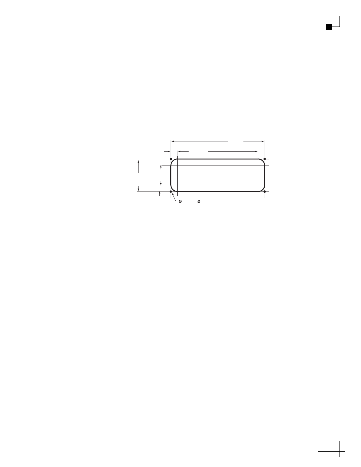
1. Using the MCP flush mounting template provided at
the end of this manual (see page 79), mark and cut out a
hole in the mounting surface to accommodate the flush
mount bracket (see Figure 2-3).
Figure 2-3 MCP Mounting Holes Layout
8.87"
.63"
(16 mm)
7.62"
(194 mm)
(225 mm)
3.08"
(78 mm)
1.83"
(46 mm)
.63"
(16 mm)
.136" ( 3.45 mm)
Mounting Hole (x4)
2. Using the same template, mark the locations for the
four MCP mounting holes.
3. Using a #29 drill bit, drill a 0.136" (3.45 mm) hole at the
four mounting hole locations. Later, you will mount the
MCP using four #8 screws.
11
Page 18
MultiSat Control Panel Owner’s Manual
Chapter 2 - Installation
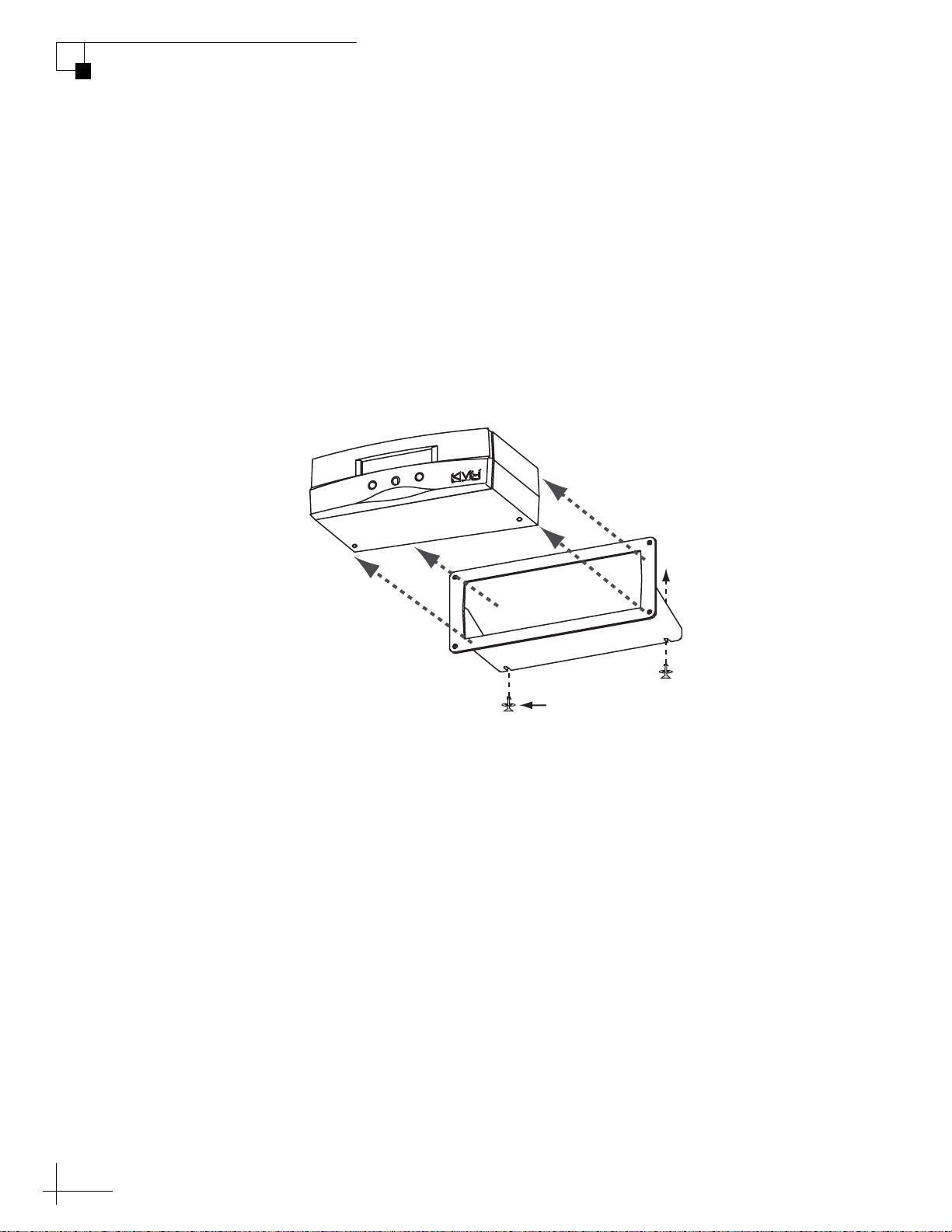
Attaching the MCP Flush Mount Bracket (Flush Mount only)
NOTE: Skip this step if you plan to mount the MCP to a horizontal surface.
1. Slide the bracket onto the MCP from behind and
position the front edge of the bracket over the seam line
between the front bezel and the chassis.
2. Secure the bracket in place using two #6-32 screws and
washers (see Figure 2-4).
Figure 2-4 MCP Flush Mount Bracket
#6-32 x 1/2" Screw
and Washer (x2)
12
Page 19
MultiSat Control Panel Owner’s Manual
Chapter 2 - Installation
Wiring the MCP to the Antenna - R4/R5 Switchplate
If you are connecting the MCP to a TracVision R4 or R5, follow the
steps in this section to wire the MCP to the switchplate.
CAUTION
For your own safety, disconnect vehicle power and make sure the
circuit is dead before you begin wiring.
Modifying the Switchplate (Optional)
To configure the switchplate for an MCP installation, follow these
steps to replace the maintenance port assembly in the switchplate with
the MCP-ready maintenance port assembly supplied in the kitpack.
NOTE: The MCP-ready maintenance port assembly moves the DB9
maintenance port to the back of the switchplate. This allows you to later
connect the main control cable to the back of the switchplate, hidden from
view. However, if you wish, you may skip this step and simply connect the
main control cable to the DB9 maintenance port on the front of the
unmodified switchplate.
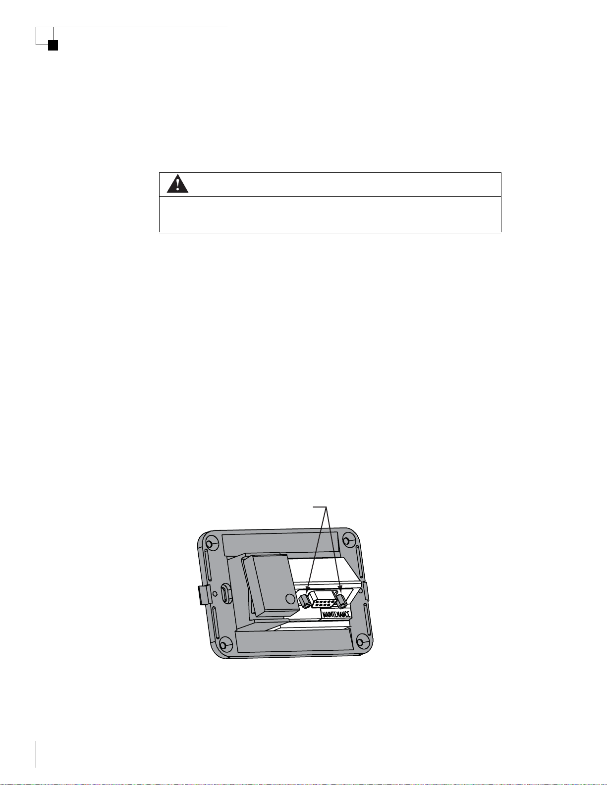
1. Remove and discard the two jack screws securing the
standard maintenance port assembly to the switchplate
(see Figure 2-5).
Figure 2-5 Detaching the Standard Maintenance Port Assembly
Remove
Jack Screws
2. Disconnect the antenna’s data/power cable from the
maintenance port assembly. You will reconnect it later.
13
Page 20
MultiSat Control Panel Owner’s Manual
Chapter 2 - Installation
3. Carefully disconnect the two power wires from the
maintenance port assembly’s power terminals. You will
reattach these wires later. Do not disconnect the power
wires connected to the switchplate itself.
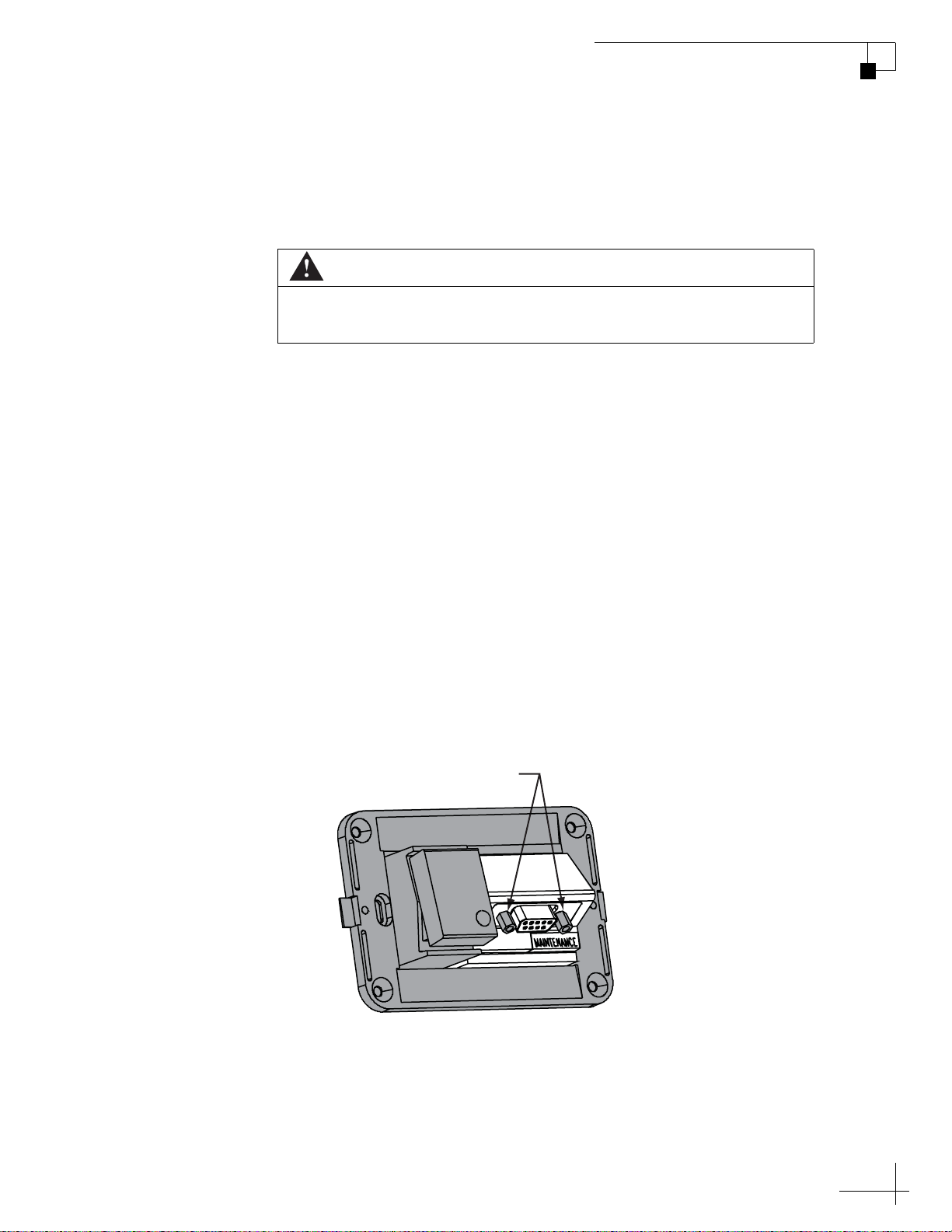
4. Remove and save the standard maintenance port
assembly (see Figure 2-6).
Figure 2-6 Standard Maintenance Port Assembly
Maintenance Port Assembly
Standard
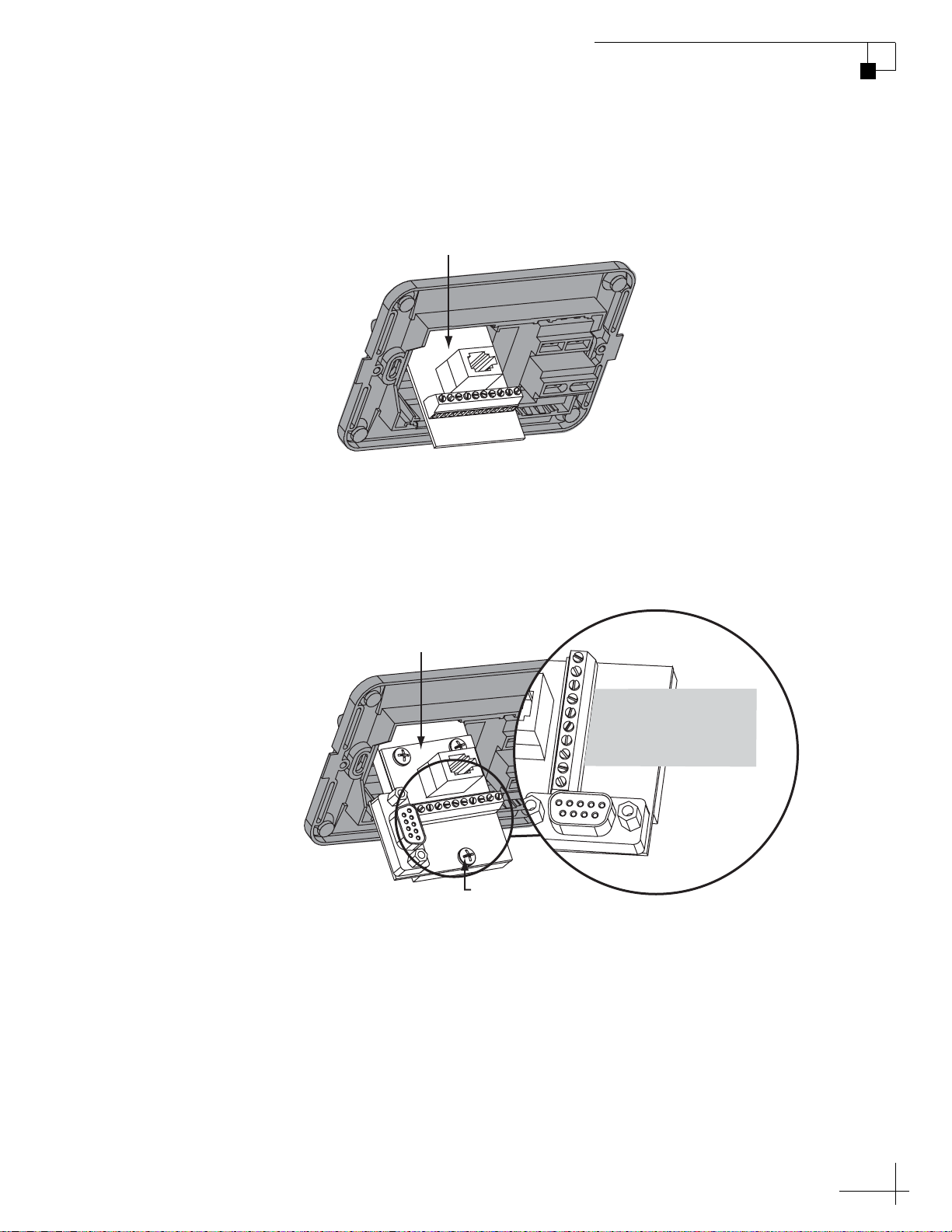
5. Attach the MCP-ready maintenance port assembly to
the switchplate using two #4-24 screws (see Figure 2-7).
These screws simply replace the jack screws you
removed in Step 1.
Figure 2-7 MCP-Ready Maintenance Port Assembly
MCP-ready
Maintenance Port Assembly
Power Wires
Antenna
Data/Power
6. Connect the switchplate’s two power wires and the
antenna’s data/power cable to the new maintenance
port assembly.
14
Page 21
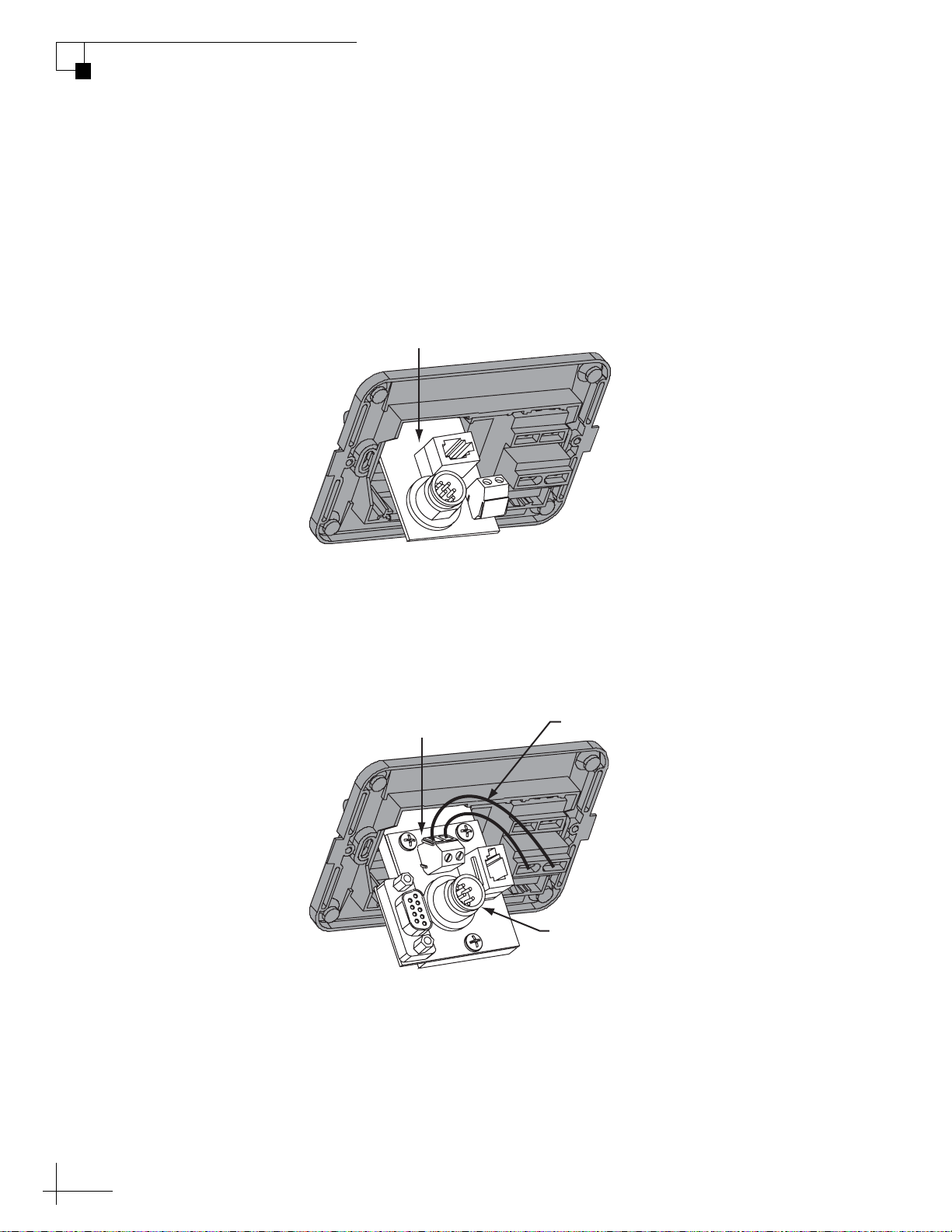
Wiring the MCP to the Switchplate
1. Connect the main control cable (DB9-male to DB9-male)
from the DB9 maintenance port jack on the switchplate
to the “Antenna Unit” jack on the MCP (see Figure 2-8).
Figure 2-8 MCP-to-Switchplate Wiring
MultiSat Control Panel Owner’s Manual
Chapter 2 - Installation
Switchplate
+
–
Main Control Power
HDTV
ANTENNA UNIT RF PORT TONE
CONTROL
RF Control
MCP
DETECT
+
FUSE POWER IN
+ / –
–
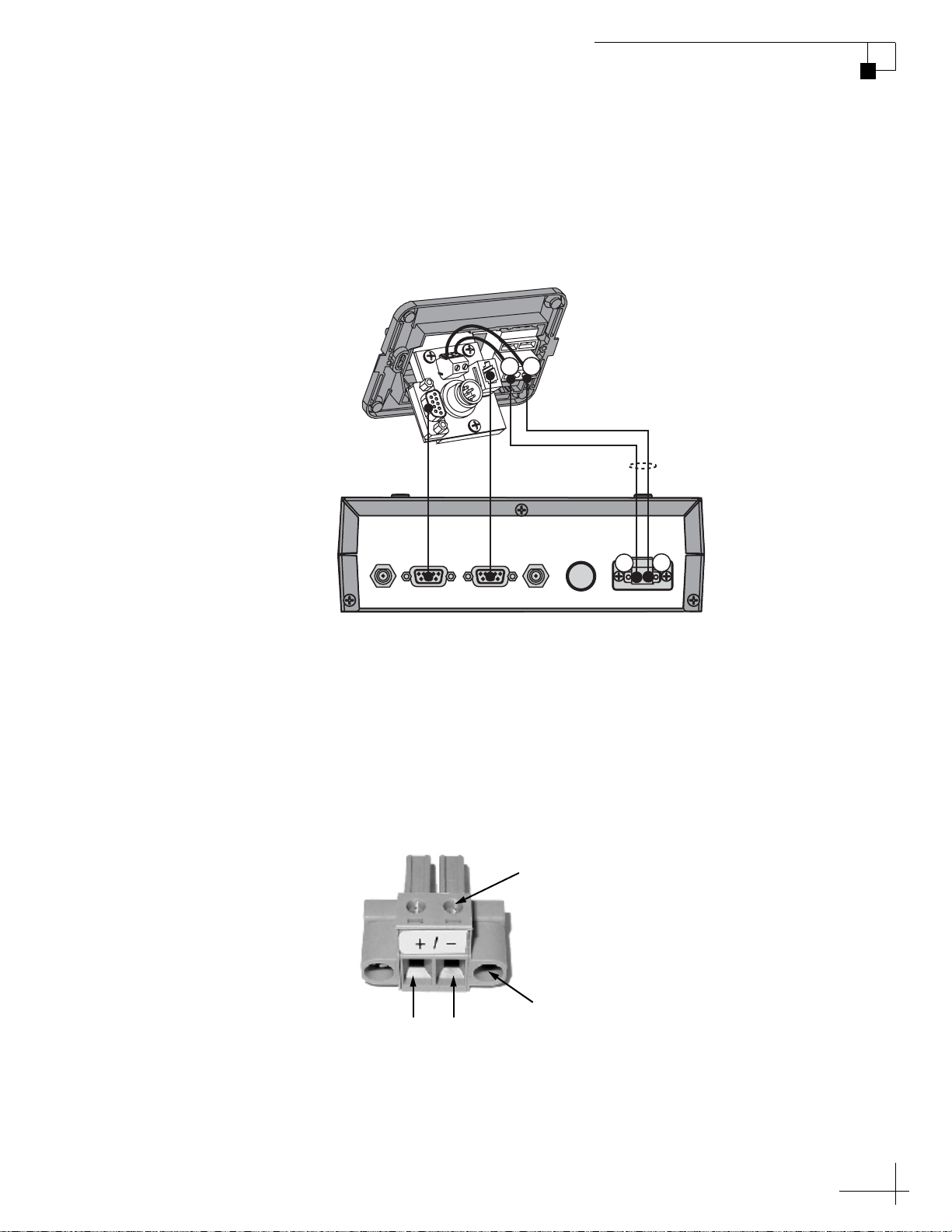
2. Connect the RF control cable (RJ22 to DB9-female) from
the RJ22 jack on the switchplate to the “RF Port” jack on
the MCP.
3. Connect a set of power wires from the switchplate’s
power output terminals to the plastic power plug
supplied in the kitpack (see Figure 2-9) (for cable
specifications, see Figure 2-1 on page 9).
Figure 2-9 MCP Power Plug
Terminal Screw (x2)
Retaining Screw (x2)
GroundPower
(11-16 VDC)
4. Plug the MCP power plug into the “Power In” jack on
the MCP. Secure in place with the retaining screws.
15
Page 22
MultiSat Control Panel Owner’s Manual
Chapter 2 - Installation
Wiring the MCP to the Antenna - M5/M7 Switchplate
If you are connecting the MCP to a TracVision M5 or M7 switchplate
configuration, follow the steps in this section to wire the MCP to the
switchplate.
CAUTION
For your own safety, disconnect vessel power and make sure the
circuit is dead before you begin wiring.
Modifying the Switchplate (Optional)
To configure the switchplate for an MCP installation, follow these
steps to replace the maintenance port assembly in the switchplate with
the MCP-ready maintenance port assembly supplied in the kitpack.
NOTE: The MCP-ready maintenance port assembly moves the DB9
maintenance port to the back of the switchplate. This allows you to later
connect the main control cable to the back of the switchplate, hidden from
view. However, if you wish, you may skip this step and simply connect the
main control cable to the DB9 maintenance port on the front of the
unmodified switchplate.
1. Remove and discard the two jack screws securing the
standard maintenance port assembly to the switchplate
(see Figure 2-10).
Figure 2-10 Detaching the Standard Maintenance Port Assembly
Remove
Jack Screws
16
2. Carefully disconnect the antenna’s data cable from the
maintenance port assembly’s terminal board. You will
reconnect these wires later.
Page 23
MultiSat Control Panel Owner’s Manual
Chapter 2 - Installation
3. Remove and save the standard maintenance port
assembly (see Figure 2-11).
Figure 2-11 Standard Maintenance Port Assembly
Standard
Maintenance Port Assembly
4. Attach the MCP-ready maintenance port assembly to
the switchplate using two #4-24 screws (see
Figure 2-12). These screws simply replace the jack
screws you removed in Step 1.
Figure 2-12 MCP-Ready Maintenance Port Assembly
MCP-ready
Maintenance Port Assembly
Attach P-clip here
Data Cable
to Antenna
YELLOW Not Used
GREEN Not Used
BRN/WHT PC GND
WHT/BRN PC TXD
ORG/WHT PC RXD
WHT/ORG RF GND
GRY/WHT RF TXD
WHT/GRY RF RXD
BLACK Not Used
NOT USED Not Used
5. Wire the TracVision antenna’s data cable to the
terminal board on the new maintenance port assembly.
Be sure to match the wire colors (body color/stripe color) with
the terminal board label.
6. Using a P-clip, strain-relieve all wires at the switchplate
by securing them to the bottom screw of the
maintenance port assembly.
17
Page 24

MultiSat Control Panel Owner’s Manual
Chapter 2 - Installation
Wiring the MCP to the Switchplate
1. Connect the main control cable (DB9-male to DB9-male)
from the DB9 maintenance port jack on the switchplate
to the “Antenna Unit” jack on the MCP (see
Figure 2-13).
Figure 2-13 MCP-to-Switchplate Wiring
Switchplate
+
–
Main Control Power
HDTV
ANTENNA UNIT RF PORT TONE
CONTROL
RF Control
MCP
DETECT
+
FUSE POWER IN
+ / –
–
2. Connect the RF control cable (RJ22 to DB9-female) from
the RJ22 jack on the switchplate to the “RF Port” jack on
the MCP.
3. Connect a set of power wires from the switchplate’s
power output terminals to the plastic power plug
supplied in the kitpack (see Figure 2-14) (for cable
specifications, see Figure 2-1 on page 9).
Figure 2-14 MCP Power Plug
Terminal Screw (x2)
18
Retaining Screw (x2)
GroundPower
(11-16 VDC)
4. Plug the MCP power plug into the “Power In” jack on
the MCP. Secure in place with the retaining screws.
Page 25

MultiSat Control Panel Owner’s Manual
Chapter 2 - Installation
Wiring the MCP to the Antenna - M5/M7 GyroTrac
If you are connecting the MCP to a TracVision M5 or M7 GyroTrac
configuration, follow the steps in this section to wire the MCP to the
GyroTrac ADCU.
CAUTION
For your own safety, disconnect vessel power and make sure the
circuit is dead before you begin wiring.
1. Connect the main control cable (DB9-male to DB9-male)
from the DB9 maintenance port jack on the ADCU to
the “Antenna Unit” jack on the MCP (see Figure 2-15).
Figure 2-15 MCP-to-ADCU Wiring
58 (Pin #5)
59 (Pin #3)
Red (+12 VDC)
Black (Ground)
60 (Pin #2)
60 59 58
60 59 505152535455 49565758
Green Label
12 1110987612543
RF Control
48 47 383940414243 37444546
13 14 232221201918 24171615
Red LabelYellow Label
Power
38 37
25 26 353433323130 36292827
ADCU
White LabelBlue Label
MCP
+
–
HDTV
ANTENNA UNIT RF PORT TONE
CONTROL
DETECT
FUSE POWER IN
+ / –
Main Control
2. Connect the RF control cable (3-wires to DB9-female)
from terminals 58, 59, and 60 on the ADCU to the “RF
Port” jack on the MCP (see Figure 2-15).
19
Page 26

3. Connect a set of power wires from terminals 37
(+12 VDC) and 38 (ground) on the ADCU to the plastic
power plug supplied in the kitpack (see Figure 2-16)
(for cable specifications, see Figure 2-1 on page 9).
Figure 2-16 MCP Power Plug
Terminal Screw (x2)
Retaining Screw (x2)
GroundPower
(11-16 VDC)
4. Plug the MCP power plug into the “Power In” jack on
the MCP. Secure in place with the retaining screws.
Page 27

Wiring the MCP to the Antenna - M9
If you are connecting the MCP to a TracVision M9, follow the steps in
this section to wire the MCP to the Master Control Unit (MCU).
CAUTION
For your own safety, disconnect vessel power and make sure the
circuit is dead before you begin wiring.
1. Connect the main control cable (DB9-male to DB9-male)
from the “Maintenance Port” jack on the MCU to the
“Antenna Unit” jack on the MCP (see Figure 2-17).
Figure 2-17 MCP-to-MCU Wiring
MCU
MultiSat Control Panel Owner’s Manual
Chapter 2 - Installation
+
OUTPUT TO
ANTENNA
MAINTENANCE PORT RF PORT
FUSE
–
POWER IN
24 VDC
Main Control
RF Control
MCP
+
–
HDTV
ANTENNA UNIT RF PORT TONE
CONTROL
DETECT
FUSE POWER IN
+ / –
12 VDC
2. Connect the RF control cable (DB9-female to
DB9-female) from the “RF Port” jack on the MCU to the
“RF Port” jack on the MCP.
21
Page 28

MultiSat Control Panel Owner’s Manual
Chapter 2 - Installation
3. Connect a set of power wires from 12 VDC vessel
power to the plastic power plug supplied in the kitpack
(see Figure 2-18).
For power cable specifications, see Figure 2-1 on
page 9).
Figure 2-18 MCP Power Plug
(11-16 VDC)
Terminal Screw (x2)
Retaining Screw (x2)
GroundPower
4. Plug the MCP power plug into the “Power In” jack on
the MCP. Secure in place with the retaining screws.
22
Page 29

MultiSat Control Panel Owner’s Manual
SATELLITE IN
Wiring the HDTV Converter and Receiver
To configure your TracVision system for DIRECTV HDTV, follow the
steps below to connect the HDTV converter between the MCP and
your DIRECTV HDTV receiver.
IMPORTANT!
If you wish to connect multiple receivers, refer to the alternate
wiring diagrams in “Appendix B” on page 69.
1. Connect an RF coax cable from the “HDTV Control”
jack on the MCP to the “Control Input” jack on the
HDTV converter (see Figure 2-19).
Figure 2-19 HDTV Converter and Receiver Wiring
Chapter 2 - Installation
RF1 Cable
from Antenna
OUT
INPUT
SATELLITE IN
HDTV
ANTENNA UNIT RF PORT TONE
CONTROL
HDTV
Converter
OUT
Splitter
TV ANT/CABLE IN
OUT TO TV
MCP
DETECT
FUSE POWER IN
DIRECTV HDTV Receiver
RL
AUDIO VIDEO S-VIDEO PHONE JACK
+ / –
2. Connect the RF1 cable from the antenna to the “RF
Input” jack on the HDTV converter.
23
Page 30

MultiSat Control Panel Owner’s Manual
Chapter 2 - Installation
3. Connect an RF coax cable from the “RF Out” jack on the
HDTV converter to either of the “Out” jacks on the
supplied splitter.
4. Connect an RF coax cable from the “Tone Detect” jack
on the MCP to the other “Out” jack on the splitter.
5. Connect an RF coax cable from the “Input” jack on the
splitter to the “Satellite In” jack on the DIRECTV HD
receiver.
24
Page 31

Mounting the MCP
Follow these steps to mount the MCP using one of the following
options:
Option 1 - Velcro mount to a horizontal surface
Option 2 - Flush mount to a vertical surface
Option 1 - Velcro Mounting
1. Clean the bottom of the MCP and the mounting surface
using a mild detergent.
2. Peel the backing from the two supplied Velcro fabric
squares and stick them to the bottom of the MCP (see
Figure 2-20).
MultiSat Control Panel Owner’s Manual
Chapter 2 - Installation
Figure 2-20 Velcro Mounting the MCP to a Horizontal Surface
Fabric Strip (x2)
Hook Disk (x2)
3. Position the two Velcro hook disks onto the mounting
surface. Drill screw holes for the disks and secure in
place with #4-24 screws.
4. Press the MCP firmly into place so the fabric’s loop
material engages the hook disks.
#4-24 Screw (x2)
25
Page 32

MultiSat Control Panel Owner’s Manual
Chapter 2 - Installation
Option 2- Flush Mounting
1. Make sure the flush mount bracket is attached to the
MCP. If it is not attached, attach the bracket as
explained in “Attaching the MCP Flush Mount Bracket
(Flush Mount only)” on page 12.
2. Insert the MCP and bracket assembly into the mounting
hole and secure in place with four #8 screws and
washers (see Figure 2-21).
Figure 2-21 Flush Mounting the MCP to a Vertical Surface
#8 Screws and
Washers (x4)
26
Page 33

Selecting the DIRECTV TriSat Group
Follow the steps below to turn on the system and set it up for TriSat
mode.
NOTE: This system is specially configured to receive DIRECTV’s standard
and HD programming from the 101, 119, and 110 satellites. However, the
antenna has the capability to track any DVB®-compatible satellite. If you do
not wish to set up the antenna to track the three DIRECTV satellites, refer to
“Selecting Satellites to Track - DualSat” on page 46 for details on
installing a different pair of satellites.
1. Ensure the antenna has a clear, unobstructed view of
the sky.
2. Apply power to the receiver(s), TV(s), and TracVision
system. Wait two minutes for system startup.
MultiSat Control Panel Owner’s Manual
Chapter 2 - Installation
3. Press the center MENU button on the MCP’s front
panel to access the onscreen menu (see Figure 2-22).
Figure 2-22 Trisat Satellite Selection Menus on MCP
Menu
Install Satellite?
Yes Next Return
Trisat mode?
Yes No Return
USA or Europe?
USA Europe Return
Installing Trisat
Group - Please wait
101, 119, and 110
sats installed
27
Page 34

MultiSat Control Panel Owner’s Manual
Chapter 2 - Installation
4. At “Install satellite?” press YES.
5. At “Trisat mode?” press YES.
6. At “USA or Europe?” press USA. The MCP installs the
TriSat group of satellites into the antenna.
7. Follow the steps in the next section to choose the Sat
Select mode.
28
Page 35

Choosing a Sat Select Mode
Now that you have selected the TriSat group of satellites, follow the
steps below to choose a Sat Select mode: Automatic or Manual (see the
next page for a brief description of each).
1. At “Set Sat Select Mode”, press AUTO to select
Automatic mode, or press MANUAL to select Manual
mode (see Figure 2-23).
Figure 2-23 Sat Select Mode Menus on MCP
Set Sat Select Mode
Auto Manual
MultiSat Control Panel Owner’s Manual
Chapter 2 - Installation
Choose one
Select SAT 101 and:
119 110 Return
Choose one
101-### Mode set
Restarting antenna
2. If you selected Automatic mode, at “Select SAT 101
and,“ select a satellite pair to track first:
•Press 119 for 101-119
•Press 110 for 101-110
After restart, the antenna will start tracking the satellite pair
you selected.
3. The antenna restarts. Wait two minutes for system
startup.
29
Page 36

MultiSat Control Panel Owner’s Manual
Chapter 2 - Installation
Sat Select Modes
In Automatic mode, the antenna automatically switches between a
pair of satellites as the user changes channels on the receiver’s remote.
The user sets the MCP to automatically switch between either 101-110
or 101-119 (see Figure 2-24).
Figure 2-24 Automatic Sat Select Mode
Alternate Pair
(101-119)
Selected
Pair
101-110:Tracking 110
119 Menu
Selected
Satellite
In Manual mode, the user presses a button on the MCP whenever he/
she wishes to switch satellites. The user can select between 101, 110,
and 119 (see Figure 2-25).
Figure 2-25 Manual Sat Select Mode
Selected
Satellite
Tracking 101
Alternate
Satellites
119 Menu 110
30
Page 37

Configuring the DIRECTV HD Receiver
Before the user can start enjoying high-definition programming, the
DIRECTV HD receiver needs to be configured for an “Oval, 3 LNB”
dish type and must be activated for HDTV service.
Changing the Dish Type on the Receiver
To receive channels from the three DIRECTV satellites (101, 119, and
110), the receiver needs to be configured for an “Oval, 3 LNB” dish
(antenna) type. Since each model of receiver is different, refer to the
receiver’s manual for details on viewing and changing the dish type
setting.
Activating the DIRECTV HDTV Service
The HD receiver will only be able to decode HD channels if it is
activated. High-definition channels are not included with the basic
DIRECTV package, and premium HD channels, such as HBO HD,
must be ordered separately. KVH makes activation easy. Just call
KVH’s Activation Department at 1-888-584-4163 (Mon.-Fri., 8:30 am 5 pm ET).
MultiSat Control Panel Owner’s Manual
Chapter 2 - Installation
31
Page 38

3. Operation
This chapter explains how to access the system menu and switch
satellites using the buttons on the control panel.
Contents
Downloading the Program Guide to the Receiver............ 35
Switching Satellites - TriSat............................................ 36
Switching Satellites - DualSat......................................... 38
Accessing the Menu ........................................................ 39
MultiSat Control Panel Owner’s Manual
Chapter 3 - Operation
33
Page 39

MultiSat Control Panel Owner’s Manual
Chapter 3 - Operation
Downloading the Program Guide to the Receiver
Whenever you turn on the HD receiver, it needs to download the
Program Guide from the 101 satellite. Be sure the antenna is tracking
the 101 satellite whenever you reboot the receiver.
Please be patient during this process - it might take more than 20
minutes for the receiver to download the entire Program Guide, which
lists channels available on every DIRECTV satellite. A channel is
selectable only if it is loaded in the Program Guide.
NOTE: The receiver downloads the channel listings for the 101 satellite first.
Then the receiver loads the channel listings for the other satellites.
TIP: For your convenience, KVH provides a list of HD channels, and the
DIRECTV satellites that carry them, on our web site at www.kvh.com/
HDlineup. Since DIRECTV changes its channel lineups frequently, KVH
can e-mail updates to you whenever the HD lineup changes. Register for this
free service when you visit the web site for the first time.
35
Page 40

MultiSat Control Panel Owner’s Manual
Chapter 3 - Operation
Switching Satellites - TriSat
If your TracVision antenna is configured to track the DIRECTV TriSat
group, your TracVision antenna will track three DIRECTV satellites in
TriSat mode:
• 101 (Primary)
• 110 (HDTV)
• 119 (Locals)
NOTE: For details on configuring the TracVision antenna for the DIRECTV
TriSat group, see “Selecting the DIRECTV TriSat Group” on page 27.
In TriSat mode, you can choose between two methods of satellite
switching: Automatic or Manual. The following sections explain how
to use each mode. For details on choosing a Sat Select mode, see
“Choosing a Sat Select Mode - TriSat Only” on page 45.
Automatic Switching
With Automatic Sat Select mode enabled, the antenna switches
between a pair of satellites automatically, as necessary, when you
change channels using the receiver’s remote control. Since the antenna
is configured to track three satellites, you can select either the 101-110
or 101-119 satellite pair on the MCP for automatic switching (see
Figure 3-1).
Figure 3-1 Automatic Satellite Switching in TriSat Mode
Selected
Alternate Pair
(101-119)
Selected
Alternate Pair
(101-110)
Pair
Pair
101-110:Tracking 110
119 Menu
101-119:Tracking 119
110 Menu
Selected
Satellite
Selected
Satellite
36
NOTE: The primary receiver, which is connected to the splitter, controls
satellite selection. All secondary receivers will only be able to receive channels
carried on the satellite that is currently selected on the primary receiver.
Page 41

Manual Switching
With Manual Sat Select mode enabled, you can manually select
satellites using the MCP front panel buttons. Simply press the button
under the desired satellite shown on the display (see Figure 3-2).
Figure 3-2 Manually Switching Satellites in TriSat Mode
MultiSat Control Panel Owner’s Manual
Chapter 3 - Operation
Tracking 101
119 Menu 110
Select
119
Selected
Satellite
Select
110
37
Page 42

MultiSat Control Panel Owner’s Manual
Chapter 3 - Operation
Switching Satellites - DualSat
If your TracVision antenna is not configured to track the DIRECTV
TriSat group, your TracVision antenna will track a pair of satellites in
DualSat mode.
NOTE: For details on selecting the satellites to track in DualSat mode, see
“Selecting Satellites to Track - DualSat” on page 46.
Automatic Switching
Most TracVision system configurations support automatic satellite
switching in DualSat mode. With automatic switching enabled, the
antenna switches satellites automatically, as necessary, when you
change channels using the receiver’s remote control.
NOTE: The primary receiver, which is connected to the splitter, controls
satellite selection. All secondary receivers will only be able to receive channels
carried on the satellite that is currently selected on the primary receiver.
Manual Switching
If your antenna configuration does not support automatic switching
(for example, DISH Network or multiswitch configurations), you can
manually select satellites using the MCP front panel buttons. Simply
press the left button to select Satellite A or the right button to select
Satellite B.
Figure 3-3 Manually Switching Satellites in DualSat Mode
Satellite A
NOTE: If you use the MCP to manually switch between satellites, automatic
satellite switching is disabled until you restart the TracVision system.
Tracking <SAT A>
<SAT A> Menu <SAT B>
Select
Select
Satellite B
Selected
Satellite
38
Page 43

Accessing the Menu
With the MCP, you can configure and control all TracVision functions
using the three buttons on the front panel. To access the menu, press
the center button (see Figure 3-4).
Figure 3-4 Accessing the Menu
MultiSat Control Panel Owner’s Manual
Chapter 3 - Operation
Tracking <SAT A>
<SAT B> Menu <SAT C>
Enter
Main Menu
Antenna
Display
Once you have accessed the menu, the functions of the three MCP
buttons are determined by the text shown directly above them on the
display. Chapter 4 explains all of the menu functions that are available,
and a quick reference guide is provided on the inside front cover of
this manual.
39
Page 44

MultiSat Control Panel Owner’s Manual
4. Menu Functions
This chapter explains the various MCP menu functions that are available
for configuring the TracVision system. Be sure to refer to the TracVision
antenna manual for further details about configuring the antenna.
Contents
Adjusting Display Brightness........................................... 43
Selecting Satellites to Track - TriSat............................... 44
Choosing a Sat Select Mode - TriSat Only....................... 45
Selecting Satellites to Track - DualSat............................ 46
Chapter 4 - Menu Functions
Manually Entering Latitude and Longitude...................... 47
Changing the Sleep Mode Setting ................................... 48
Changing the Instant On Mode Setting............................ 49
Restarting the Antenna.................................................... 50
Viewing Antenna Status .................................................. 51
Manually Controlling the Antenna ................................... 53
Updating Satellite Frequency Data .................................. 54
Configuring Satellite Settings.......................................... 56
Upgrading Software......................................................... 57
41
Page 45

Adjusting Display Brightness
g
Follow the process shown in Figure 4-1 to adjust the brightness of the
MCP display.
Figure 4-1 Setting Display Brightness
MultiSat Control Panel Owner’s Manual
Chapter 4 - Menu Functions
<Default Display>
Select Next until “Operations
Mode?” is displayed.
Yes Next Return
Get Antenna Status?
Yes Next Return
Select Next until “Set
Brightness?” is displayed.
Yes Next Return
Min Bright Max
************
Press to
Dim
Menu
Operations Mode?
Set Brightness?
Press to
Accept
Press to
Bri
hten
43
Page 46

MultiSat Control Panel Owner’s Manual
Chapter 4 - Menu Functions
Selecting Satellites to Track - TriSat
Follow the process shown in Figure 4-2 to select the DIRECTV TriSat
group, consisting of the 101, 110, and 119 satellites.
Figure 4-2 Selecting Satellites - TriSat
<Default Display>
Menu
Install Satellite?
Yes Next Return
TriSat Mode?
Yes No Return
USA or Europe?
USA Europe Return
Installing Trisat
Group - Please wait
101, 119, and 110
sats installed
Set Sat Select Mode
Auto Manual
Select SAT 101 and:
119 110 Return
Choose one
101-### Mode set
Choose one
Manual Mode Set
44
Page 47

MultiSat Control Panel Owner’s Manual
Choosing a Sat Select Mode - TriSat Only
If your system is set up for TriSat mode, follow the process shown in
Figure 4-3 to choose a Sat Select mode: Automatic or Manual. For
details about these modes, see “Sat Select Modes” on page 30.
Figure 4-3 Choosing a Sat Select Mode
Chapter 4 - Menu Functions
<Default Display>
Menu
Set Sat Select Mode?
Yes Next Return
Auto or Manual?
Auto Manual Return
Select the satellite pair you
wish to track.
Select SAT 101 and:
119 110 Return
101-### Mode set
Manual Mode set
45
Page 48

MultiSat Control Panel Owner’s Manual
Chapter 4 - Menu Functions
Selecting Satellites to Track - DualSat
Follow the process shown in Figure 4-4 to select a pair of satellites
from the TracVision antenna’s satellite library.
Figure 4-4 Selecting Satellites - DualSat
<Default Display>
Menu
Install Satellite?
Yes Next Return
TriSat Mode?
Yes No Return
Select Next as required to
display your choice for
Satellite A, then select Yes.
Install A <SAT Name>
Yes Next Cancel
Select Next as required to
display your choice for
Satellite B (or choose None
to track just one satellite),
then select Yes.
Install B <SAT Name>
Yes Next Cancel
Installing Sats
Please Wait
<SAT A> and
<SAT B> installed
Restarting antenna
46
Page 49

MultiSat Control Panel Owner’s Manual
Manually Entering Latitude and Longitude
Follow the process shown in Figure 4-5 to manually enter your
vessel’s/vehicle’s latitude and longitude into the antenna. The
antenna will use your position information to speed up satellite
acquisition.
Figure 4-5 Entering Latitude and Longitude
Chapter 4 - Menu Functions
<Default Display>
Menu
Install Satellite?
Yes Next Return
Select Next until “Operations
mode?” is displayed.
Operations mode?
Yes Next Return
Get antenna status?
Yes Next Return
Select Next until “Control
antenna?” is displayed.
Control antenna?
Yes Next Return
Man control antenna?
Yes Next Return
Select Next Until “Set
Lat/Long?” is displayed.
Set Lat/Long?
Yes Next Return
Latitude: ##N
- Enter +
Longitude: ###E
- Enter +
Latitude: ##N
Longitude: ####E
Select -/+ as
required to set
latitude and
longitude, then
select Enter.
IMPORTANT!
Be sure to restart the antenna after entering a new latitude and
longitude. The antenna updates its stored position information
only upon restart. For details on restarting the antenna, see
“Restarting the Antenna” on page 50.
47
Page 50

MultiSat Control Panel Owner’s Manual
Chapter 4 - Menu Functions
Changing the Sleep Mode Setting
Follow the process shown in Figure 4-6 to set Sleep Mode on or off.
With Sleep Mode enabled, when the vessel/vehicle comes to a stop
and holds its position for one minute (e.g., at a dock), the antenna unit
locks the antenna in place to conserve power. As soon as the vessel/
vehicle moves beyond a 1° - 2° window or the signal level changes
significantly, Sleep Mode automatically turns off and the system
begins tracking the satellite again.
Figure 4-6 Setting Sleep Mode On/Off
<Default Display>
Select Next until “Operations
Mode?” is displayed.
Yes Next Return
Get Antenna Status?
Yes Next Return
Yes Next Return
Man Control Antenna?
Yes Next Return
Set Sleep on/off?
Yes Next Return
On Enter Off
Select On or Off as required,
then select Enter.
Menu
Operations Mode?
Control Antenna?
Sleep Mode: ON
48
Page 51

MultiSat Control Panel Owner’s Manual
Changing the Instant On Mode Setting
Follow the process shown in Figure 4-7 to set Instant On Mode on or
off.
When Instant On is enabled, the antenna will immediately receive
signals when the antenna is turned on, as long as the vessel/vehicle
has not moved since the antenna was last shut off. However, if the
system was turned off, and then the vessel/vehicle moved, after last
acquiring the satellite via Instant On, the antenna will undergo its
standard initialization process. This results in a brief delay.
Figure 4-7 Setting Instant On Mode On/Off
Chapter 4 - Menu Functions
<Default Display>
Select Next until “Operations
Mode?” is displayed.
Yes Next Return
Get Antenna Status?
Yes Next Return
Yes Next Return
Select Next until “Set instant
on/off?” is displayed.
Set instant on/off?
Yes Next Return
instant mode: Off
On Enter Off
Select On or Off as required,
then select Enter.
Menu
Operations Mode?
Control Antenna?
49
Page 52

MultiSat Control Panel Owner’s Manual
Chapter 4 - Menu Functions
Restarting the Antenna
Follow the process shown in Figure 4-8 to restart the antenna.
Figure 4-8 Restarting the Antenna
<Default Display>
Select Next until “Restart
Antenna?” is displayed.
Yes Next Return
Antenna Restarted
Menu
Restart Antenna?
50
Page 53

Viewing Antenna Status
Follow the process shown in Figure 4-9 to view antenna status
information. Figure 4-10 lists the status information that is provided
on each screen.
Figure 4-9 Antenna Status Screens
MultiSat Control Panel Owner’s Manual
Chapter 4 - Menu Functions
<Default Display>
Menu
Select Next until “Operations
Mode?” is displayed.
Operations Mode?
Yes Next Return
Get Antenna Status?
Yes Next Return
Press any button to continue.
No errors detected
Testing OK
CP Antenna RF
#.## #.## #.#
Antenna Serial #
#########
Signal level = ####
Threshold = ####
Skew angle
##.#
Bit error rate
###
Get System Errors?
Yes Next Return
Get Version?
Yes Next Return
Get Serial Number?
Yes Next Return
Get Thres/sig level?
Yes Next Return
Get skew angle?
Yes Next Return
Get bit error rate?
Yes Next Return
Get state?
Yes Next Return
State
<Current State>
51
Page 54

MultiSat Control Panel Owner’s Manual
Chapter 4 - Menu Functions
Figure 4-10 Antenna Status Information
MCP Screen Description
Get System Errors Performs the following tests and reports
Get Version Reports the following software versions:
errors:
• Azimuth motor
• Elevation motor
• Antenna gyro (if applicable)
• Sensor (if applicable)
•RF comms
• RF signal
•RF config
• Control Panel
• Antenna (Main board)
•RF board
Get Serial Number Reports the antenna serial number
Get Thres/Sig Level Reports the currently received RF signal
level and threshold (minimum RF level for
satellite acquisition)
Get Skew Angle Reports the ideal LNB skew angle for the
currently selected satellite - Does not apply
to North American antenna systems
Get Bit Error Rate Reports the received signal’s bit error rate
(higher number = more errors)
Get State Reports the current state of the antenna:
• Initializing
• Searching
•Tracking
•Idle
• Error
52
Page 55

Manually Controlling the Antenna
Follow the process shown in Figure 4-11 to manually position the
antenna.
NOTE: If you are performing this procedure as part of the satellite frequency
scan update procedure, be sure to select “NO” at the “Make Antenna Track”
screen.
Figure 4-11 Manually Controlling the Antenna
MultiSat Control Panel Owner’s Manual
Chapter 4 - Menu Functions
<Default Display>
Select Next until “Operations
Mode?” is displayed.
Yes Next Return
Get Antenna Status?
Yes Next Return
Yes Next Return
Man Control Antenna?
Yes Next Return
Select - or + as required,
then select Azimuth.
AZ = XXX.X° EL = XX.X°
- Azimuth +
Menu
Operations Mode?
Control Antenna?
Select - or + as required,
then select Elevation.
AZ = XXX.X° EL = XX.X°
- Elevation +
make antenna track?
Yes No Cancel
53
Page 56

MultiSat Control Panel Owner’s Manual
Chapter 4 - Menu Functions
Updating Satellite Frequency Data
NOTE: This function is only available in TracVision M5/M7/M9.
If the antenna is unable to find a satellite, or if you are unable to
receive certain channels, the satellite’s frequency data might have
changed. The satellite frequency scan feature allows you to update the
frequency data of any satellite stored in the system’s library. With the
desired satellite, band, and polarization selected, the system will
automatically scan for the frequency with the strongest signal. The
system will then update that satellite’s programmed data with the new
frequency (and associated network ID) and store it in the satellite
library.
IMPORTANT!
DO NOT use this function unless directed by KVH Technical
Support or a KVH-authorized technician. Improper data selection
will affect system performance.
TIP: During this process, you will need to enter the symbol rate and FEC
code. You can find this satellite data on the web at www.lyngsat.com or
www.satcodx.com (neither website is affiliated with KVH).
To update the satellite frequency data, follow the steps below.
IMPORTANT!
The vessel must remain stationary throughout this procedure.
1. Set your satellite receiver to the signal meter mode.
Refer to your receiver’s manual for details.
IMPORTANT!
Ensure that the TV signal meter indicates that you have
a strong signal.
2. If the system is unable to locate the selected satellite,
you can manually point the antenna. Refer to
“Manually Controlling the Antenna” on page 53 for
details.
54
3. Using the receiver, select the desired polarization and
band. Refer to your selected receiver’s user manual for
details.
Page 57

MultiSat Control Panel Owner’s Manual
Chapter 4 - Menu Functions
4. Follow the process shown in Figure 4-12 to scan the
frequency data of the selected satellite.
NOTE: Scanning satellite frequencies might take up to 10 minutes.
Figure 4-12 Scanning Frequency Data
<Default Display>
Menu
Select Next until “Operations
Mode?” is displayed.
Operations Mode?
Yes Next Return
Get Antenna Status?
Yes Next Return
Control Antenna?
Yes Next Return
Man Control Antenna?
Yes Next Return
Select Next until “Sat
Frequency Scan?” is displayed.
Sat frequency Scan?
Yes Next Return
Select -/+ as required, then
select Enter (valid range is
01000 - 39999 kilosymbols
per second).
Symbol Rate: XXXXX
- Enter +
Select -/+ as required, then
select Enter (valid codes are
1/2, 2/3, 3/4, 5/6, 6/7, and 7/8).
Set FEC Code: X/X
- Enter +
Scan frequencies
Please wait
Update frequency?
Yes No
Updating frequency
Please wait
Restart antenna?
Yes No
55
Page 58

MultiSat Control Panel Owner’s Manual
Chapter 4 - Menu Functions
Configuring Satellite Settings
NOTE: This function is only available in TracVision M5/M7/M9.
Follow the process shown in Figure 4-13 to configure one of the
satellites you have selected for tracking. Circular satellites use two
polarizations: right-hand circular (RHC) and left-hand circular (LHC).
Figure 4-13 Configuring a Satellite
<Default Display>
Menu
Select Next until “Operations
Mode?” is displayed.
Operations Mode?
Yes Next Return
Get Antenna Status?
Yes Next Return
Control Antenna?
Yes Next Return
Man Control Antenna?
Yes Next Return
Select Next until “Configure
Satellite?” is displayed.
Configure Satellite?
Yes Next Return
Configure frequency?
Yes Next Cancel
Select -/+ as required, then
select Enter (valid
range is 00000, 10700 12750 MHz).
Set freq: #####MHZ
- Enter +
Configure symbol rate?
Yes Next Cancel
Select -/+ as required, then
select Enter (valid range is
01000 - 45000 kilosymbols
per second).
Sym Rate: #####M/S
- Enter +
Configure FEC Code?
Yes Next Cancel
56
Configure Satellite
Sat A Sat B Sat C
Configure <Sat Name>?
Yes Next Return
Select -/+ as required, then
select Enter (valid
polarizations are LHC, RHC,
HH, HL, VH, VL).
Polarization: ###
- Enter +
Select -/+ as required, then
select Enter (valid codes are
1/2, 2/3, 3/4, 5/6, 6/7, 7/8).
Set FEC Code: #/#
- Enter +
Configure Network ID?
Yes Next Cancel
Select -/+ as required, then
select Enter (valid range is
0x0000 - 0xffff hex).
Set ID: ######HEX
- Enter +
Page 59

Upgrading Software
A KVH-authorized technician can upgrade (“flash”) the software in
the antenna by connecting a laptop computer to the control panel and
running the KVH Flash Update Wizard.
NOTE: KVH-authorized technicians can download the latest version of the
KVH Flash Update Wizard, along with flashing instructions, from the KVH
Partner Portal.
Before beginning the software upgrade, follow the process shown in
Figure 4-14 to halt the antenna.
Figure 4-14 Preparing the Antenna for a Software Upgrade
<Default Display>
Menu
MultiSat Control Panel Owner’s Manual
Chapter 4 - Menu Functions
Select Next until “Operations
Mode?” is displayed.
Operations Mode?
Yes Next Return
Get Antenna Status?
Yes Next Return
Select Next until “Upgrade
Software?” is displayed.
Upgrade Software?
Yes Next Return
^RF Use Jack Main^
HALT Return
System Halted
57
Page 60

MultiSat Control Panel Owner’s Manual
5. Troubleshooting
This chapter identifies potential problems that might occur following an
MCP installation, along with their possible causes and solutions. It also
explains how to get technical support. For antenna-specific
troubleshooting information, refer to the TracVision antenna manual.
Contents
Five Simple Checks ......................................................... 61
Technical Support............................................................ 62
Field Replaceable Units ................................................... 63
Chapter 5 - Troubleshooting
59
Page 61

Five Simple Checks
If you are experiencing a problem with the MCP, perform the five
simple checks below.
Is the antenna set to manual satellite switching?
If you cannot switch satellites using the receiver’s remote control, the
antenna might be set up for manual switching. If the system is
configured for DIRECTV TriSat mode, refer to “Choosing a Sat Select
Mode - TriSat Only” on page 45 for details on selecting the Automatic
Sat Select mode. If the system is configured for a pair of satellites in
DualSat mode, simply turn the antenna off, then back on. In DualSat
mode, the antenna enters manual switching whenever you press an
MCP button to manually select a satellite.
MultiSat Control Panel Owner’s Manual
Chapter 5 - Troubleshooting
Has the receiver downloaded the Program Guide?
If the receiver hasn’t downloaded the entire Program Guide from the
satellite during startup, a “Channel Not Available” message might
appear on the TV. Make sure the antenna is tracking the 101 satellite
and wait for the Program Guide to load. It might take 20 minutes to
complete.
Is the selected channel carried on a different satellite?
If you select a channel on the receiver, but the wrong programming or
no programming appears on the TV, that channel might be carried on
a different satellite from the one the antenna is currently tracking. Try
switching to another satellite.
TIP: For your convenience, KVH provides a list of HD channels, and the
DIRECTV satellites that carry them, on our web site at www.kvh.com/
HDlineup.
Is the receiver configured for an “Oval, 3 LNB” dish type?
To receive channels from three DIRECTV satellites in TriSat mode, the
receiver needs to be configured for an “Oval, 3 LNB” dish/antenna
type. Refer to your receiver’s manual for details on viewing and
changing the receiver’s dish type setting.
Is the MCP connected properly to the TracVision system?
Check the rear panel of the MCP and ensure all cables are connected
properly. Also be sure the TracVision system is turned on; the MCP
receives its power from the TracVision system.
61
Page 62

MultiSat Control Panel Owner’s Manual
Chapter 5 - Troubleshooting
Technical Support
The MCP and TracVision system are sophisticated electronic devices;
only KVH-authorized technicians have the tools and expertise
necessary to diagnose and repair a system fault. Therefore, if you
experience any operating problem or require technical assistance,
please call or visit your local authorized TracVision dealer or
distributor. You can find an authorized technician near you by visiting
our website at www.kvh.com/wheretogetservice.
If you need help finding an authorized technician, please contact KVH
Technical Support:
Phone: +1 401 847-3327
E-mail: techs@kvh.com
Please have your antenna and MCP serial numbers handy before you
call.
62
Page 63

Field Replaceable Units
Part numbers for field replaceable units (FRUs) that can be serviced in
the field are listed in Figure 5-1. These parts can be obtained from any
KVH-authorized dealer or distributor.
Figure 5-1 MCP Field Replaceable Units
Part Part Number
MCP 02-1401
MultiSat Control Panel Owner’s Manual
Chapter 5 - Troubleshooting
Main control cable
(9-pin male to 9-pin male), 25 ft.
RF control cable, switchplate version
(9-pin female to RJ22), 25 ft.
RF control cable, ADCU version
(9-pin female to 3 wires), 25 ft.
RF control cable, MCU (M9) version
(9-pin female to 9-pin female), 25 ft.
Flash cable
(9-pin female to stereo plug), 5.9 ft.
Switchplate maintenance port assembly,
TracVision M5/M7 version
Switchplate maintenance port assembly,
TracVision R4/R5 version
MCP rear-panel fuse (0.5 amp) 16-0017-0500
HDTV converter 02-1431
32-0716-25
32-0811
32-0618-25
32-0901-25
32-0807
02-1192
02-1192-01
Splitter 19-0366
63
Page 64

MultiSat Control Panel Owner’s Manual
Appendix A - Computer Diagnostics
Appendix A Computer Diagnostics
This appendix explains how to connect a laptop PC to the antenna
system via the MCP.
Contents
Connecting a Laptop PC to the Main Flash Port .............. 67
65
Page 65

MultiSat Control Panel Owner’s Manual
Appendix A - Computer Diagnostics
Connecting a Laptop PC to the Main Flash Port
Since the MCP is wired directly to the TracVision system’s
maintenance port, the maintenance port is no longer available for
computer diagnostics. Instead, you need to connect your laptop PC to
the main flash port on the MCP (see Figure A-1). The main flash port
has the same functionality as the maintenance port and is conveniently
located on the MCP’s front panel.
Figure A-1 Main Flash Port on MCP
Main Flash Port
To connect your laptop PC to the main flash port, use the supplied
flash adapter cable (DB9-female to stereo plug) (see Figure A-2).
Figure A-2 Flash Adapter Cable
Stereo Plug - Connect to MCP
DB9 - Connect to Laptop
TIP: If your laptop does not have a DB9 serial COM port, you can use the
following USB-to-RS232 adapters: IO Gear Part # GUC232A (visit
www.iogear.com) or Belkin Part # F5U109 (visit www.belkin.com).
Now you can use Windows® HyperTerminal or, if you are a KVHauthorized technician, the KVH Flash Update Wizard, to view antenna
diagnostics data and enter antenna commands. Refer to the TracVision
antenna manual for complete details.
67
Page 66

Appendix B Wiring Diagrams
This appendix provides system wiring diagrams for various antenna and
receiver configurations.
Contents
Wiring 1 HD Receiver - R4/R5 Configuration ................... 71
Wiring 2 or More HD Receivers -
R4/R5 Configuration ........................................................ 72
MultiSat Control Panel Owner’s Manual
Appendix B - Wiring Diagrams
Wiring 1 HD Receiver -
M5/M7 Switchplate Configuration................................... 73
Wiring 2 or More HD Receivers -
M5/M7Switchplate Configuration.................................... 74
Wiring 1 HD Receiver -
M5/M7 GyroTrac Configuration........................................ 75
Wiring 2 or More HD Receivers -
M5/M7 GyroTrac Configuration........................................ 76
Wiring 1 HD Receiver - M9 Configuration........................ 77
Wiring 2 or More HD Receivers - M9 Configuration......... 78
69
Page 67

Wiring 1 HD Receiver - R4/R5 Configuration
SATELLITE IN
SATELLITE IN
C
Antenna
RF2
RF1
HDTV
Converter
(02-1431)
MultiSat Control Panel Owner’s Manual
Appendix B - Wiring Diagrams
Data/Power
+12 VDC
+
–
+
–
Switchplate
MCP
Splitter
(19-0366)
OUT
INPUT
OUT
+
–
HDTV
ANTENNA UNIT RF PORT TONE
CONTROL
DETECT
Primary (HD) Receiver
TV ANT/CABLE IN
RL
SATELLITE IN
OUT TO TV
AUDIO VIDEO S-VIDEO PHONE JACK
FUSE POWER IN
+ / –
(controls satellite selection)
Gnd to switchplate
DC Return (-)
Secondary (Non-HD) Receiver - Optional
TV ANT/CABLE IN
RL
SATELLITE IN
OUT TO TV
AUDIO VIDEO S-VIDEO PHONE JACK
Gnd to switchplate
DC Return (-)
+12 VD
71
Page 68

MultiSat Control Panel Owner’s Manual
SATELLITE IN
SATELLITE IN
C
Appendix B - Wiring Diagrams
Wiring 2 or More HD Receivers - R4/R5 Configuration
Antenna
RF1
RF2
Data/Power
+12 VDC
HDTV
Converter
(02-1431)
RHCP
+13V
Multiswitch
+12 VDC
Gnd to
switchplate
DC Return (-)
Additional HD or
Standard Receivers
OUT
LHCP
+18V
INPUT
OUT
Splitter
(19-0366)
+
–
+
–
HDTV
ANTENNA UNIT RF PORT TONE
CONTROL
DETECT
Primary HD Receiver #1
(controls satellite selection)
TV ANT/CABLE IN
RL
SATELLITE IN
OUT TO TV
AUDIO VIDEO S-VIDEO PHONE JACK
Switchplate
+
FUSE POWER IN
+ / –
MCP
–
+12 VD
72
HD Receiver #2
TV ANT/CABLE IN
SATELLITE IN
OUT TO TV
RL
AUDIO VIDEO S-VIDEO PHONE JACK
Page 69

MultiSat Control Panel Owner’s Manual
SATELLITE IN
SATELLITE IN
C
Wiring 1 HD Receiver - M5/M7 Switchplate Configuration
Antenna
Appendix B - Wiring Diagrams
RF2
Converter
(02-1431)
HDTV
(19-0366)
Splitter
RF1
OUT
INPUT
OUT
Data
+
–
+
–
HDTV
ANTENNA UNIT RF PORT TONE
CONTROL
DETECT
Primary (HD) Receiver
TV ANT/CABLE IN
RL
SATELLITE IN
OUT TO TV
AUDIO VIDEO S-VIDEO PHONE JACK
Power
+12 VDC
Switchplate
MCP
+
–
FUSE POWER IN
+ / –
+12 VD
(controls satellite selection)
Gnd To switchplate
DC Return (-)
Secondary (Non-HD) Receiver - Optional
TV ANT/CABLE IN
RL
SATELLITE IN
OUT TO TV
AUDIO VIDEO S-VIDEO PHONE JACK
Gnd To switchplate
DC Return (-)
73
Page 70

MultiSat Control Panel Owner’s Manual
SATELLITE IN
SATELLITE IN
C
Appendix B - Wiring Diagrams
Wiring 2 or More HD Receivers - M5/M7 Switchplate Configuration
Antenna
RF1
Converter
(02-1431)
+12 VDC
HDTV
RHCP
+13V
RF2
Multiswitch
LHCP
+18V
Data
HDTV
ANTENNA UNIT RF PORT TONE
CONTROL
Power
+12 VDC
–
–
Switchplate
+
+
MCP
+
–
DETECT
FUSE POWER IN
+ / –
+12 VD
Gnd to switchplate
DC Return (-)
Additional HD or
Standard Receivers
74
OUT
INPUT
OUT
Splitter
(19-0366)
Primary HD Receiver #1
(controls satellite selection)
TV ANT/CABLE IN
RL
SATELLITE IN
OUT TO TV
AUDIO VIDEO S-VIDEO PHONE JACK
HD Receiver #2
TV ANT/CABLE IN
RL
SATELLITE IN
OUT TO TV
AUDIO VIDEO S-VIDEO PHONE JACK
Page 71

Wiring 1 HD Receiver - M5/M7 GyroTrac Configuration
SATELLITE IN
SATELLITE IN
Antenna
MultiSat Control Panel Owner’s Manual
Appendix B - Wiring Diagrams
RF2
RF1
HDTV
Converter
(02-1431)
58 (Pin #5)
59 (Pin #3)
60 (Pin #2)
60 59 58
Data
Power
ADCU
Refer to TracVision manual for antenna wiring information
60 59 505152535455 49565758
Yellow Label
Green Label
12 1110987612543
48 47 383940414243 37444546
13 14 232221201918 24171615
Vessel Power
Red Label
White LabelBlue Label
25 26 353433323130 36292827
Sensor
(12 VDC)
MCP
+
–
HDTV
ANTENNA UNIT RF PORT TONE
CONTROL
DETECT
FUSE POWER IN
+ / –
+12 VDC
OUT
Splitter
(19-0366)
INPUT
OUT
Primary (HD) Receiver
TV ANT/CABLE IN
SATELLITE IN
OUT TO TV
(controls satellite selection)
RL
AUDIO VIDEO S-VIDEO PHONE JACK
Gnd To ADCU DC Return
(terminal #2)
Secondary (Non-HD) Receiver - Optional
TV ANT/CABLE IN
RL
SATELLITE IN
OUT TO TV
AUDIO VIDEO S-VIDEO PHONE JACK
Gnd To ADCU DC Return
(terminal #2)
75
Page 72

MultiSat Control Panel Owner’s Manual
SATELLITE IN
SATELLITE IN
Appendix B - Wiring Diagrams
Wiring 2 or More HD Receivers - M5/M7 GyroTrac Configuration
Antenna
RHCP
+13V
RF1
RF2
HDTV
Converter
(02-1431)
Multiswitch
LHCP
+18V
Data
Power
ADCU
Refer to TracVision manual for antenna wiring information
60 59 505152535455 49565758
Green Label
12 1110987612543
58 (Pin #5)
59 (Pin #3)
60 (Pin #2)
60 59 58
48 47 383940414243 37444546
Red LabelYellow Label
13 14 232221201918 24171615
Vessel Power
(12 VDC)
White LabelBlue Label
25 26 353433323130 36292827
Sensor
MCP
+
–
Gnd to ADCU
DC Return
(terminal #2)
76
Additional
HD or
Standard
Receivers
OUT
+12 VDC
OUT
INPUT
Splitter
(19-0366)
HDTV
ANTENNA UNIT RF PORT TONE
CONTROL
DETECT
Primary HD Receiver #1
TV ANT/CABLE IN
SATELLITE IN
OUT TO TV
HD Receiver #2
TV ANT/CABLE IN
SATELLITE IN
OUT TO TV
FUSE POWER IN
+12 VDC
(controls satellite selection)
RL
AUDIO VIDEO S-VIDEO PHONE JACK
RL
AUDIO VIDEO S-VIDEO PHONE JACK
+ / –
Page 73

SATELLITE IN
SATELLITE IN
C
Wiring 1 HD Receiver - M9 Configuration
Antenna
MultiSat Control Panel Owner’s Manual
Appendix B - Wiring Diagrams
RF2
Converter
HDTV
Splitter
RF1
OUT
INPUT
Data/Power
OUT
+24 VDC
OUTPUT TO
ANTENNA
MAINTENANCE PORT RF PORT
HDTV
ANTENNA UNIT RF PORT TONE
CONTROL
DETECT
Primary (HD) Receiver
TV ANT/CABLE IN
RL
SATELLITE IN
OUT TO TV
AUDIO VIDEO S-VIDEO PHONE JACK
MCU
+
–
FUSE
POWER IN
MCP
+
–
FUSE POWER IN
+ / –
+12 VD
(Controls satellite selection)
Gnd to MCU
DC Return (-)
Secondary (Non-HD) Receiver - Optional
TV ANT/CABLE IN
RL
SATELLITE IN
OUT TO TV
AUDIO VIDEO S-VIDEO PHONE JACK
Gnd to MCU
DC Return (-)
77
Page 74

MultiSat Control Panel Owner’s Manual
SATELLITE IN
SATELLITE IN
C
Appendix B - Wiring Diagrams
Wiring 2 or More HD Receivers - M9 Configuration
Antenna
RF1
Converter
+12 VDC
HDTV
RHCP
+13V
RF2
Multiswitch
LHCP
+18V
Data/Power
OUTPUT TO
ANTENNA
MAINTENANCE PORT RF PORT
HDTV
ANTENNA UNIT RF PORT TONE
CONTROL
+24 VDC
FUSE
DETECT
FUSE POWER IN
+
POWER IN
+
MCU
–
MCP
–
+ / –
+12 VD
Gnd to MCU
DC Return (-)
Additional HD or
Standard Receivers
78
OUT
INPUT
OUT
Splitter
Primary HD Receiver #1
(controls satellite selection)
TV ANT/CABLE IN
RL
SATELLITE IN
OUT TO TV
AUDIO VIDEO S-VIDEO PHONE JACK
HD Receiver #2
TV ANT/CABLE IN
RL
SATELLITE IN
OUT TO TV
AUDIO VIDEO S-VIDEO PHONE JACK
Page 75

8.87"
(225 mm)
MCP Flush Mounting Template
7.62"
(194 mm)
4x R .63" (16 mm)
4x .136" (3.45 mm)
.63"
(16 mm)
1.83"
(46 mm)
3.08"
(78 mm)
.63"
(16 mm)
79
Page 76

© Copyright 2006-2007, KVH Industries, Inc. KVH and TracVision are registered trademarks of KVH Industries, Inc.
KVH Industries, Inc.
50 Enterprise Center • Middletown, RI 02842-5279 • U.S.A.
Phone: +1 401 847-3327 • Fax: +1 401 849-0045
E-mail: info@kvh.com
KVH Europe A/S
Kokkedal Industripark 2B • 2980 Kokkedal • Denmark
Phone: +45 45 160 180 • Fax: +45 45 160 181
E-mail: info@kvh.dk
www.kvh.com
 Loading...