

Page 1
TracVision®LF/SF Installation Guide
These instructions explain how to install the TracVision LF/SF
satellite TV antenna system on a vehicle. Complete instructions
on how to use the system are provided in the User’s Guide and
the selected receiver’s owner ’s manual.
Step See Page:
1. Inspect Parts and Get Tools 2
2. Plan the Installation 3
3. Remove the Shipping Restraint 4
4. Mount the Antenna 5
5. Cut the Switchplate Mounting Hole 6
6. Wire the Antenna 7
7. Seal the Cable Access Hole 8
8. Wire the Receiver(s) 9
9. Wire the Switchplate 10
10. Mount the Switchplate 11
11. Test the System 12
1
54-0286 Rev. A
Technical Support
If you need technical assistance,
please contact KVH Technical Support:
Phone: 1-401-847-3327
E-mail: techs@kvh.com
Internet: www.kvh.com/help
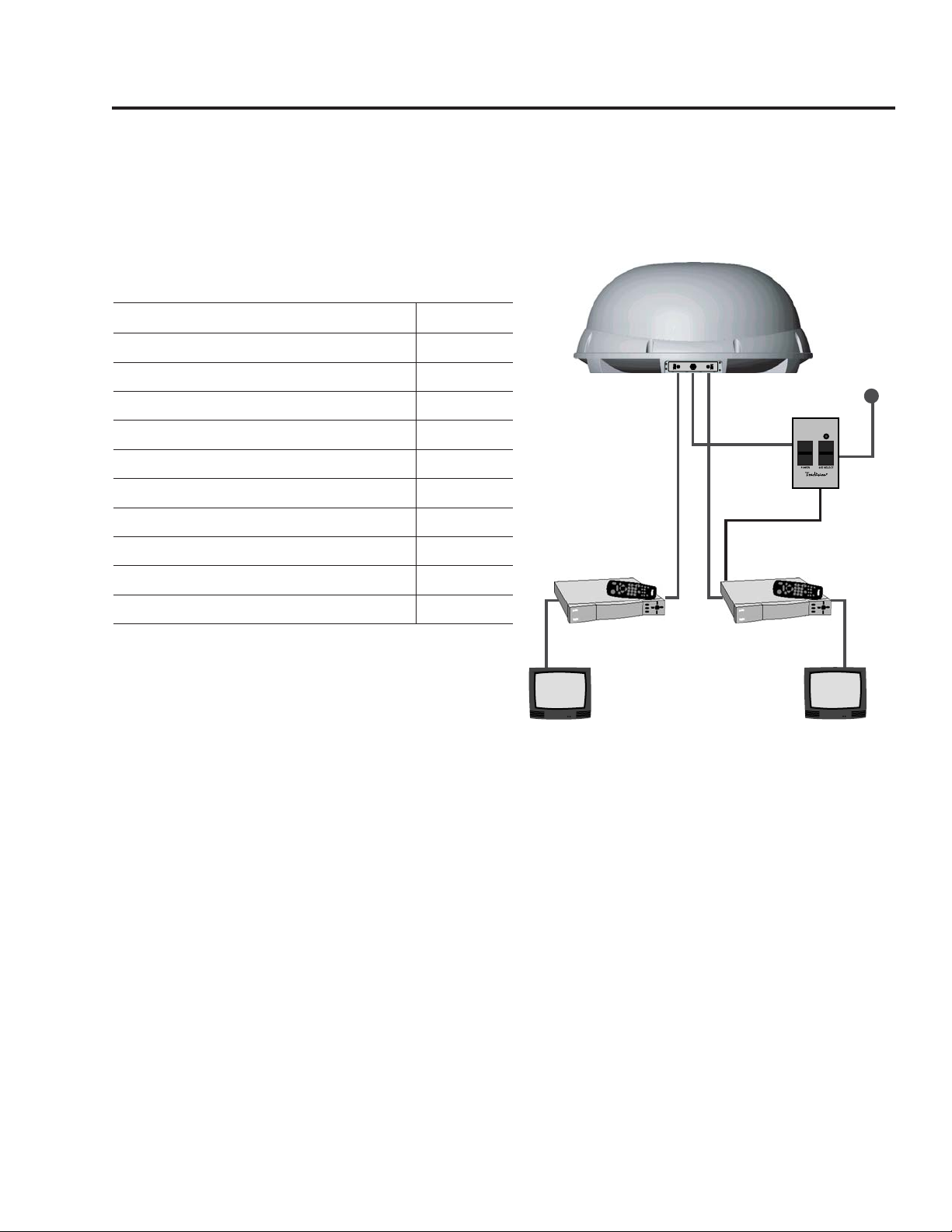
Satellite Receiver 1
RF2
TV 1
Data/Power
Vehicle
Power
12 VDC
Switchplate
Satellite Receiver 2
TV 2
TracVision Antenna
RF1
Low-speed Data
(optional)
(DIRECTV
®
only)
Page 2

2
1. Unpack the box and ensure it contains everything
shown on the Contents List. Note: Cables for the
LF/SF system are stored beneath the antenna unit
during shipping.
2. Carefully examine all of the supplied parts to
ensure nothing was damaged in shipment.
3. Gather all of the tools and materials listed below.
You will need these items to complete the
installation.
• Electric drill
• 3⁄16" drill bit
• 3⁄4" hole saw and auger bit
• #2 Phillips and #0 flat tip screwdrivers
• Silicone sealant or RTV
• 7⁄16"-open end wrench
• Adhesive suitable for specific roof
construction and materials (e.g., Liquid Nails)
• Rivet gun and 3⁄16"-rivets (or other fastener
suitable for specific roof construction)
• RG6 or RG11 (75 ohms) RF cable (if installing
more than one receiver)
• Augat IT1000 Tool (KVH part #19-0242)
• Snap-N-Seal®F-connector(s)
(KVH part #23-0170)
Inspect Parts and Get Tools
1
Always lift the antenna unit by the
gray baseplate, never by the
radome!
Page 3
3
54-0286 Rev. A
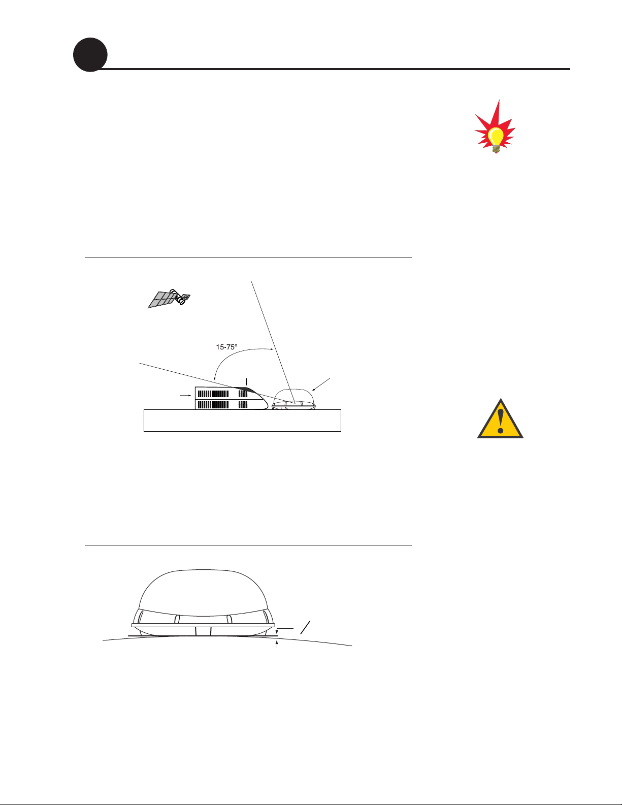
Before you begin, consider the following installation guidelines:
• The antenna requires a 15° to 75° look angle and
must have an unobstructed view of the southern
sky to receive satellite TV.
• Find a location on a flat part of the roof on the
centerline of the vehicle, away from any
obstructions that might block the satellite signal
(the antenna should be at least 18" away from the
nearest air conditioner).
Figure 1
Antenna Blockage
• The antenna must be mounted on a horizontal
surface with a minimum roof (or other mounting
surface) radius of 250". When placed flat on the
mounting surface, the mounting plates should be
less than
7
⁄16" above the mounting surface (see
Figure 2).
Figure 2
Maximum Mounting Surface Slope
• When choosing a location for the switchplate, find
a dry, flat location that will be easily accessible to
the user. Take into account cable lengths between
components, as well as accessibility to the
equipment after installation.
If you need to paint the radome,
use ONLY non-metallic
automotive paint without a
primer coat. Metallic paint or paint
having metallic color will block
satellite signals.
Plan the Installation
2
Any gap larger than 7⁄16" will warp
the baseplate and seriously
damage the antenna.
Blocked!
Air Conditioner
Vehicle Roof
TracVision Antenna
7
16
" Maximum Gap
Page 4
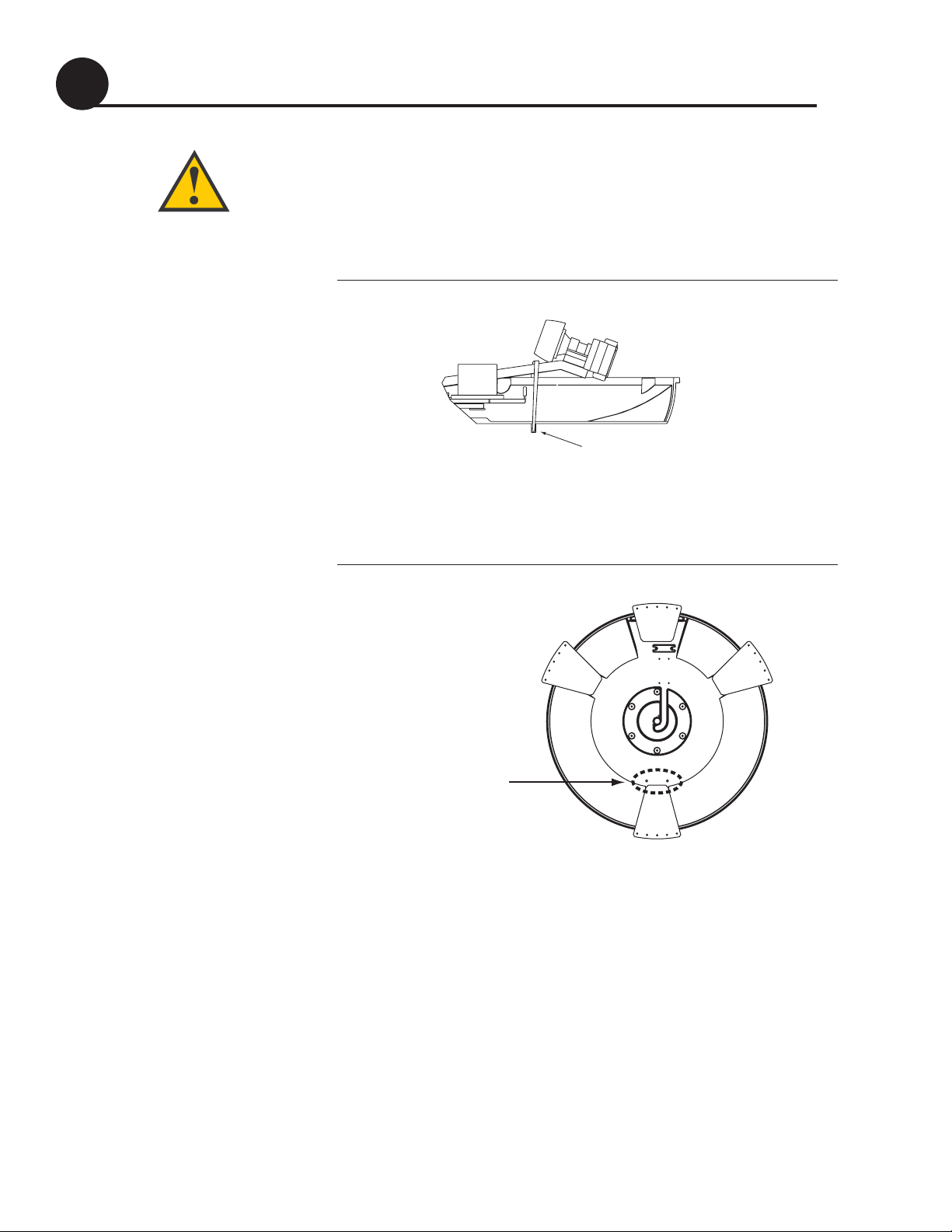
1. At the bottom of the antenna baseplate, cut the tie-
wrap and pull it out of the baseplate. You do not
need to remove the radome. This tie-wrap secures the
antenna’s LNB (low-noise block) to prevent
shipping damage (see Figure 3).
Figure 3
Shipping Restraint
2. After removing the tie-wrap, seal the two holes
with the plugs provided in the kitpack (see
Figure 4).
Figure 4
Antenna Baseplate (Bottom View)
4
Once you remove the shipping
restraint, handle the antenna unit
carefully. Improper handling may
damage the unit.
Remove the Shipping Restraint
3
Shipping Restraint (Tie-wrap)
Seal two tie-wrap holes
Page 5
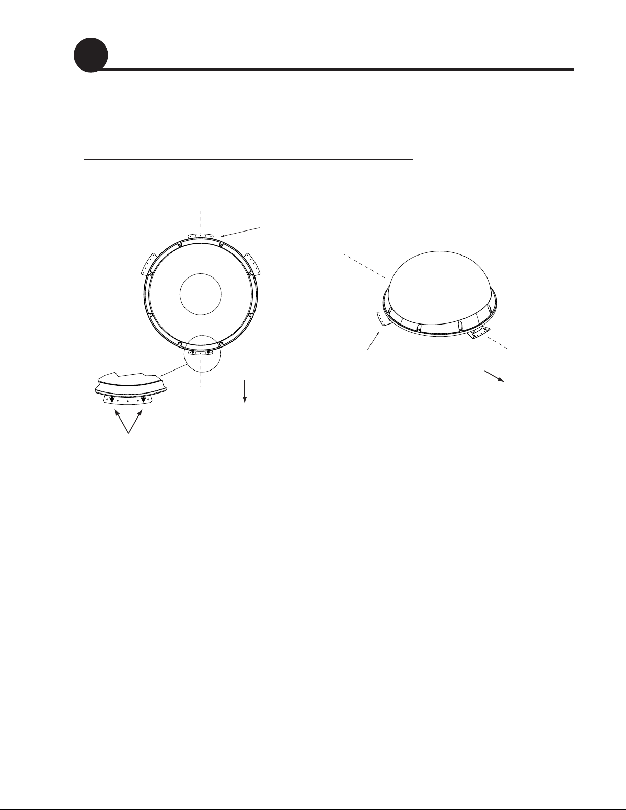
1. Apply construction adhesive to the bottom of the
antenna’s four mounting plates across all of the
holes.
Figure 5
Proper Orientation of the Antenna Unit
2. Place the antenna on the roof on the centerline of
the vehicle so that the two arrows on the antenna’s
front mounting plate point toward the front of the
vehicle.
3. Attach the four mounting plates to the roof using
20
3
⁄16"-diameter rivets (or other appropriate
fasteners).
4. Seal the rivets/screws with silicone sealant (or
equivalent).
5
54-0286 Rev. A
Mount the Antenna
4
Forward Mounting
Plate Arrows
Vehicle
Centerline
Baseplate
Connectors
Front of
Vehicle
Top View Side View
Vehicle
Centerline
Mounting Plate
(1 of 4)
Front of
Vehicle
Page 6

Cut the Switchplate Mounting Hole
1. Find a dry, flat location inside the vehicle within
27 feet of the antenna for mounting the
switchplate. The switchplate must be easily
accessible to the user.
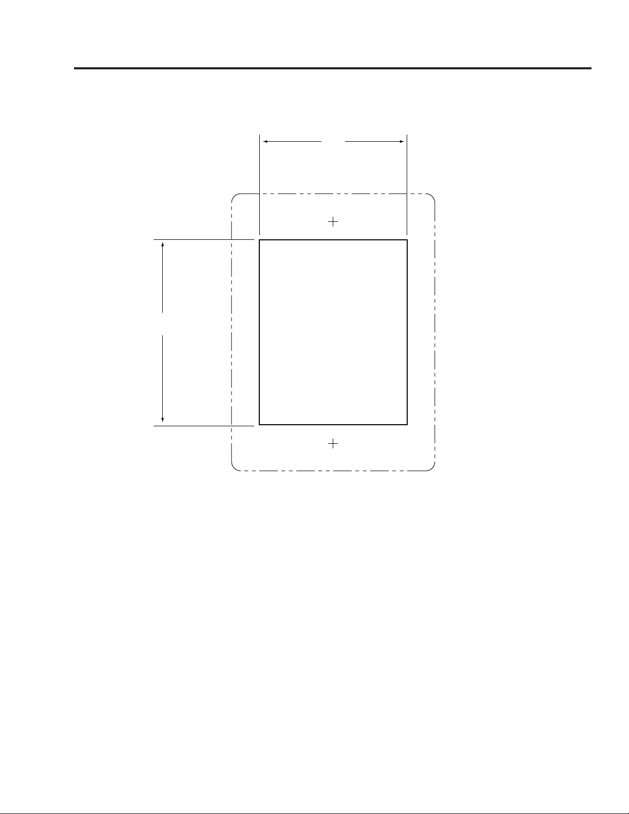
2. Using the template supplied in Appendix B, cut
out the switchplate mounting hole in the
mounting surface.
Figure 6
Switchplate Cutout Dimensions
6
5
A full-size template has been
provided for you in Appendix B.
2"
2.5"
Page 7

Wire the Antenna
1. Mark a location on the roof for the cable access
hole. You will route cables from the antenna
through the hole and into the vehicle.
2. Drill the
3
⁄4" cable access hole in the location you
marked in the previous step.
3. Connect the antenna data/power cable to the
antenna’s center connector (see Figure 7).
Figure 7
Antenna Baseplate Connectors
4. Connect one RF cable to the antenna’s “RF1”
connector. Tighten the sealing nut, found at the
base of the connector, onto the end of the RF cable.
If you plan to connect more than one receiver,
connect a second RF cable to the “RF2” connector.
5. Route the cables down through the access hole in
the roof. Be sure to maintain a service loop
(approximately 8") on the roof to allow plenty of
slack.
6. Route the data/power cable to the switchplate
location inside the vehicle.
7. Route the RF1 cable to the primary satellite TV
receiver.
8. (Optional) Route the RF2 cable to the second
receiver, if applicable.
6
Leave the protective cap installed
on the RF2 connector unless
connecting a second RF cable to
the TracVision LF/SF.
7
54-0286 Rev. A
RF2
(Optional, to 2nd
Receiver)
Data/Power
(to Switchplate)
RF1
(to Receiver)
Page 8
8
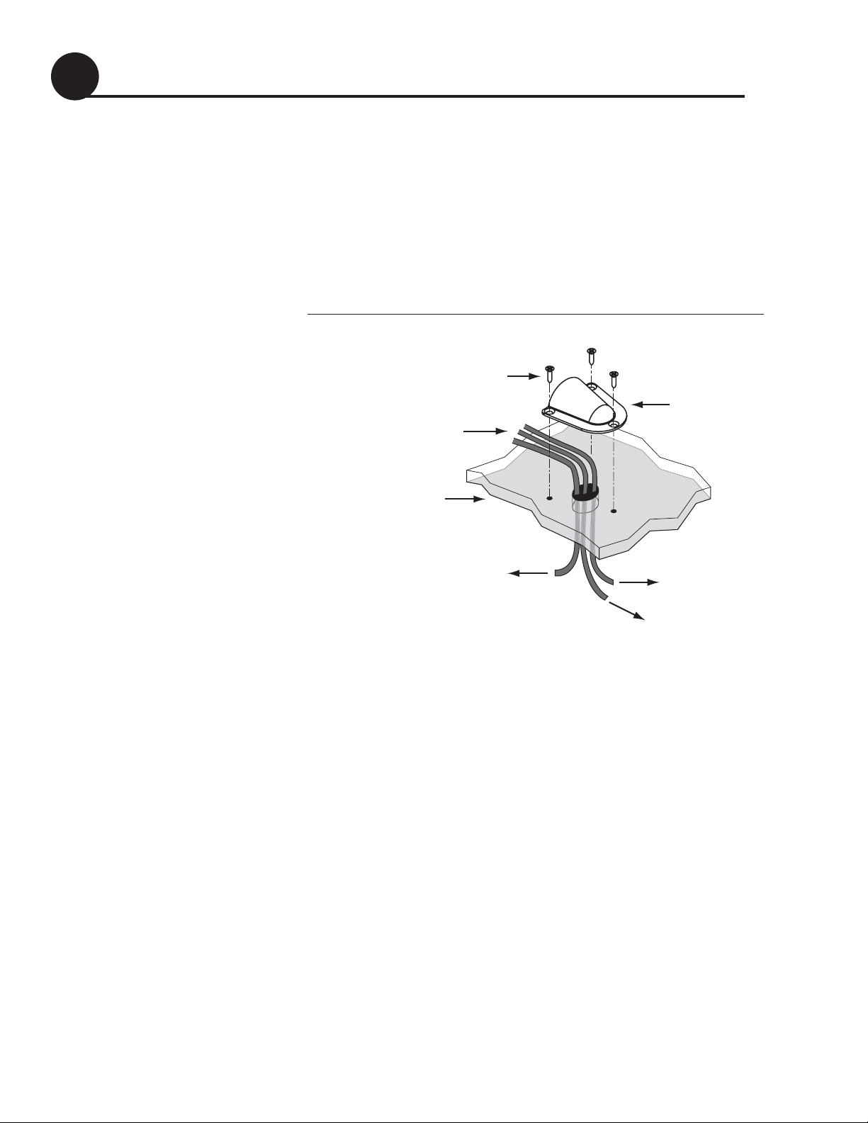
1. Seal the cable access hole with a liberal amount of
silicone sealant or RTV to protect against leakage.
2. Install the clamshell ventilator supplied in the
kitpack. It must be mounted with the opening
facing the rear of the vehicle over the cable access
hole using three of the supplied #6 screws (see
Figure 8).
Figure 8
Installing the Clamshell Ventilator
Seal the Cable Access Hole
7
Data/Power and RF Cables
(2nd RF Cable Optional)
#6 Screw
Vehicle Roof
RF2,
(to Receiver #2)
Optional
Clamshell
Ventilator
RF1
(to Receiver #1)
Data/Power
(to Switchplate)
Page 9

1. Connect the RF1 cable to the primary receiver’s
“Satellite In” connector (see Figure 9).
Figure 9
Receiver Rear Panel Connections (Example)
2. Connect the supplied ground wire to any screw on
the receiver’s rear panel. Connect the other end to
a suitable ground.
3. If you need to connect two receivers, connect the
RF2 cable and a second ground wire to the second
receiver. If you need to connect more than two
receivers, you will need to install an active
multiswitch; see Appendix A.
4. (DIRECTV Only) If your primary receiver is a
DIRECTV
®
receiver equipped with a low-speed
data port, you can connect the receiver to the
switchplate (see Figure 9). This allows the receiver
to control satellite selection. Connect the supplied
data cable (a standard RJ11 telephone handset
cord) to the receiver’s low-speed data port. Route
the other end of the data cable to the switchplate
location.
Wire the Receiver(s)
8
9
54-0286 Rev. A
SATELLITE IN
TV ANT/CABLE IN
DATA PORT
SATELLITE IN
DATA PORT
(NOT SATELLITE)
OUT TO TV
RL
AUDIO VIDEO S-VIDEO
DIGITAL
AUDIO OUT
PHONE JACK
Page 10
10
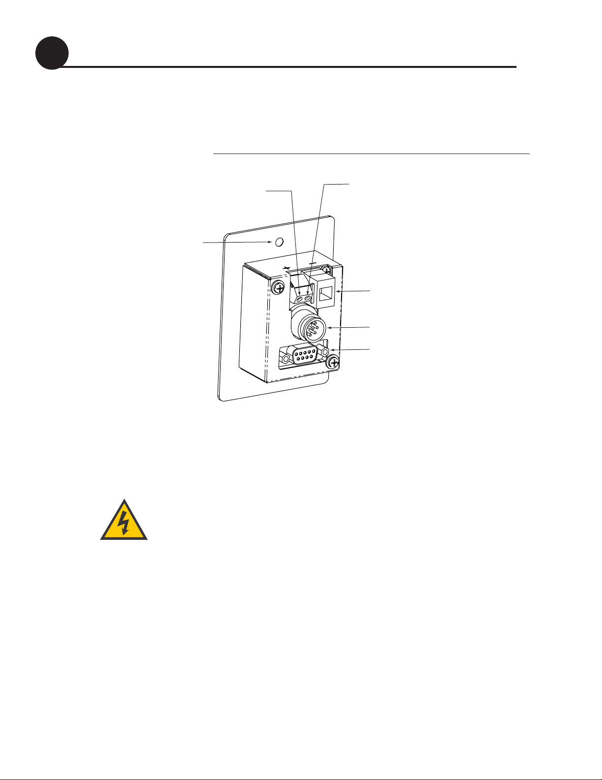
1. Connect the antenna’s data/power cable to the
switchplate’s data/power connector and lock in
place.
Figure 10
Switchplate Connections
2. If you connected a data cable to a DIRECTV
receiver’s low-speed data port (see page 9), connect
the other end of the data cable to the switchplate’s
RJ11 jack (see Figure 10).
3. Disconnect the vehicle’s power by removing the
appropriate vehicle fuse. Test the circuit to ensure
that no power is present.
4. Connect the vehicle power and ground wires to
the switchplate terminals (see Figure 10). The
antenna requires clean +12 VDC, 5-amp power.
Therefore, KVH strongly recommends using a
12 VDC, 5-amp AC/DC power supply to power
the TracVision LF/SF system.
Before connecting vehicle power,
disconnect power by removing the
appropriate vehicle fuse. Test the
circuit to ensure that no power is
present.
Wire the Switchplate
9
Switchplate Mounting
Hole (1 of 2)
Input Power
(+12 VDC)
Ground
RJ11 Jack
(Data Cable to Receiver
Data/Power Connector
Maintenance Port
(DB9 Connector)
- Optional
)
Page 11

1. Carefully fit the switchplate assembly into the
panel cutout you created earlier (see page 6).
2. Secure the switchplate to the mounting surface
using two supplied #6 screws (see Figure 11).
Figure 11
Mounting the Switchplate
3. Reinstall the vehicle fuse you removed earlier (see
page 10).
Mount the Switchplate
10
11
54-0286 Rev. A
#6 Screw
Page 12

12
Now all you need to do is turn the system on and follow the
steps below to test the TracVision system.
1. Park the vehicle in a blockage-free area. The
antenna requires an unobstructed view of the
southern sky to receive satellite signals.
2. Turn on the receiver(s) and TV(s). For instructions
on operating the receiver, refer to the receiver’s owner’s
manual.
3. Set the switchplate’s power switch to the ON (up)
position (see Figure 12).
Figure 12
Switchplate Power Switch Positions
4. Wait several minutes for system startup and initial
satellite acquisition.
5. Verify that a program guide appears on the TV.
Only the preview channels are viewable until the
customer activates the receiver. If no picture is
seen, check the connections and ensure the
antenna is tracking the correct satellite. See the
User’s Guide for details.
6. (TracVision LF only) Take a road test and verify that
the antenna tracks the satellite while the vehicle is
moving.
7. When you have finished testing, download the
KVH Flash Wizard for free at www.kvh.com/wizard.
Follow the directions on the webpage to obtain
any software updates (if applicable).
For information on operation,
troubleshooting, and DISH 500
Configuration, please refer to the
User’s Guide.
Test the System
11
Status Light
ON
OFF
The customer must activate the
receiver to watch satellite TV.
To activate a DIRECTV receiver,
call KVH at 1-888-584-4163.
To activate a DISH Network
receiver, call 1-800-333-DISH.
To activate an ExpressVu receiver,
call 1-888-SKY-DISH.
Be sure to leave the
User’s Guide
and
Product Registration Form
inside the vehicle for the customer
.
Page 13

Appendix A Installing 3
+
Receivers
Connecting more than two receivers requires an active
multiswitch (KVH part # 19-0123, Channel Master model
6214IFD, or equivalent). Install the multiswitch between the
antenna unit and the receivers. Figure 13 illustrates a typical
wiring arrangement for three or four receivers. If you need to
connect more than four receivers, contact KVH for additional wiring
instructions.
Figure 13
Using an Active Multiswitch
(DIRECTV Only) Attach the
low-speed data cable to the master
receiver. The master receiver must
remain on for the secondary
receivers to function properly.
Instead of grounding individual
receivers, as explained on page 9,
you can simply ground the
multiswitch.
A1
54-0286 Rev. A
TracVision Receiver Data Cable
Connector on Switchplate (Optional)
TracVision RF Connectors
RF1
DC Power
DC In RHCP
Out 1 Out 2 Out 3 Out 4
Receiver #1 Receiver #2 Receiver #4Receiver #3
+13V
Multiswitch
VHF/UHF LHCP
+18V
RF2
Page 14
B1
54-0286 Rev. A
Appendix B Switchplate Template
2"
2.5"
 Loading...