

Page 1
TracVision R6ST Installation Guide
These instructions explain how to install the TracVision R6ST satellite TV antenna system on an
RV or motor coach. Complete instructions on how to use the system are provided in the User’s
Guide.
Installation Steps
1. Inspect Parts and Get Tools...3
2. Plan the Installation...4
3. Remove the Restraints...5
4. Mount the Antenna...6
5. Wire the Antenna...7
6. Wire the Receiver...8
7. Connect Power...9
8. Mount the Receiver...10
9. Test the System...11
10. Educate the Customer...12
Who Should Install the System?
To ensure a safe and effective installation, KVH recommends that a KVH-authorized technician
install the TracVision R6ST system. To find a technician near you, please visit www.kvh.com/
wheretogetservice. If you purchased the product and decide to install it yourself, please see the
enclosed warranty statement for warranty implications.
Related Documentation
The following additional documents are provided with the TracVision R6ST system:
Document
Description
User’s Guide Complete operation, setup, and troubleshooting
information
Product Registration Form Details on registering the product with KVH
Warranty Statement Warranty terms and conditions
Contents List List of every part supplied in the kit
Technical Support
If you need technical assistance, please contact KVH Technical Support:
Phone: +1 401 847-3327
E-mail: techs@kvh.com
KVH, TracVision, and the unique light-colored dome with contrasting baseplate are registered trademarks of KVH Industries, Inc.
All other trademarks are property of their respective companies. The information in this document is subject to change without notice.
No company shall be liable for errors contained herein. © 2007 KVH Industries, Inc., All rights reserved. 54-0333 Rev. B
1
Page 2
1
Inspect Parts and Get Tools
a. Unpack the box and ensure it contains
everything shown on the Contents List.
Save the packaging for future use.
IMPORTANT!
Always lift the antenna by the
baseplate and never by the radome or
any portion of the internal antenna
assembly (see Figure 1).
b. Carefully examine all of the supplied
parts to ensure nothing was damaged in
shipment.
c. Gather all of the tools and materials listed
below. You will need these items to
complete the installation.
• Phillips and flat-head screwdrivers
• 7/16" open-end wrench
Figure 1 TracVision R6ST Antenna
Radome
Base
Figure 2 Activation Card
XXXXXXXXX
Antenna
XXXXXXXXX
Affix Serial
Number Here
• Silicone sealant, RTV, or equivalent
• Construction adhesive suitable for the
roof
• 5/8" - diameter hole saw
• Augat IT1000 crimp/strip tool
(KVH P/N 19-0242)
• Eight 1/4" fasteners (optional, see
“Mount the Receiver” on page 10)
• Fasteners suitable for mounting the
antenna to the roof
• RF modulator (if necessary, see
the Antenna” on page 7
d. Peel off the extra serial number label
(taped to the antenna) and affix it to the
appropriate box on red Activation Card
(see Figure 2).
)
“Wire
3
Page 3
2
Plan the Installation
Before you begin, consider the following
installation guidelines:
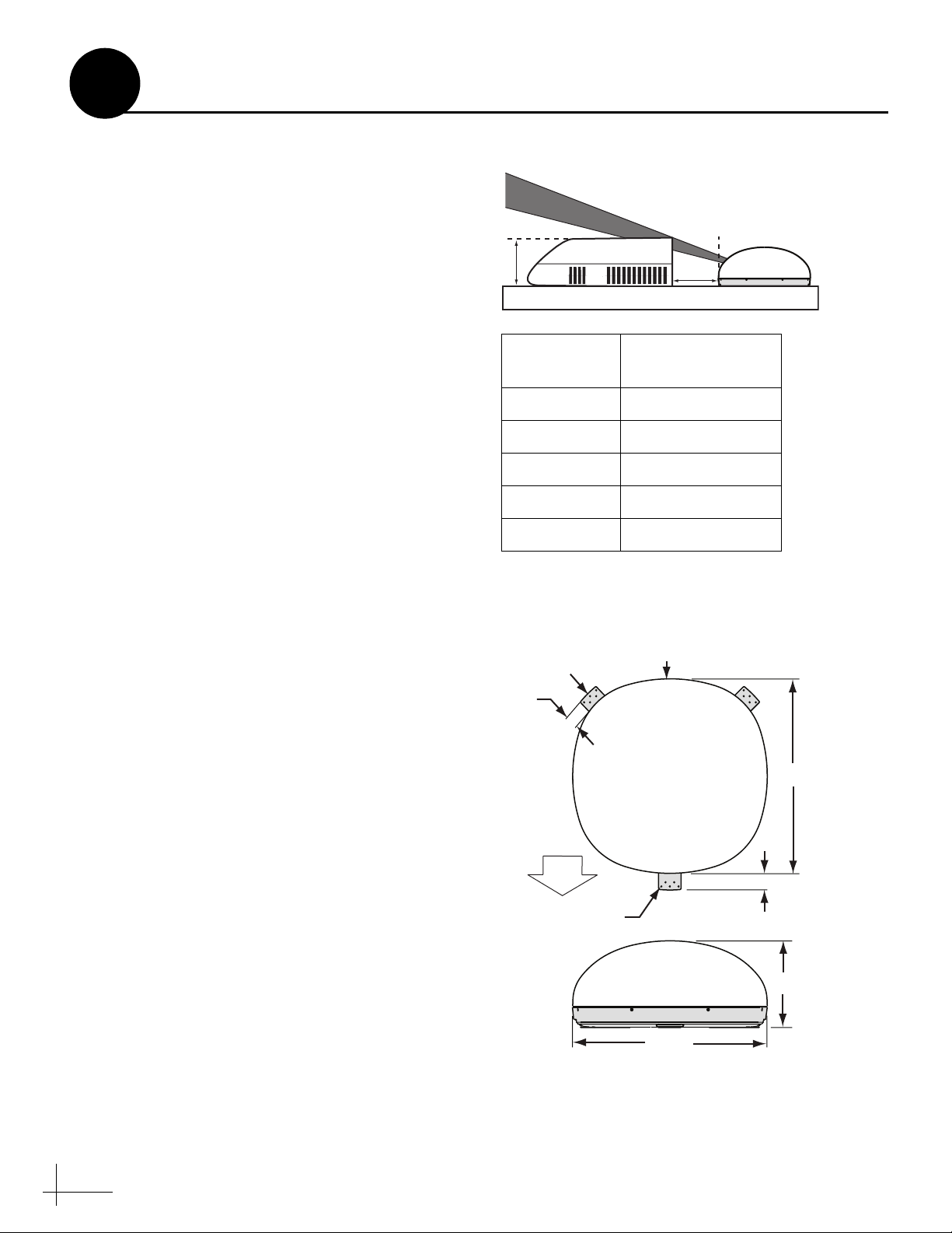
• Minimize blockage. The antenna needs a
clear view of the sky to receive satellite TV.
Using the table in Figure 3 as a guide, mount
the antenna a suitable distance away from
obstructions on the roof, such as air
conditioners.
• Ensure the mounting surface is flat and
strong enough to support the 28-lb antenna.
When placed on the mounting surface, all
three mounting plates must lay flat against
the roof (within 7/16") to avoid warping the
base and damaging the antenna.
• The antenna must be mounted on the
centerline of the vehicle with the antenna’s
cable connector facing the rear of the vehicle.
• Be sure to mount the antenna near enough to
the receiver to allow you to connect the 28-ft.
coax cable, while still maintaining sufficient
slack in the cable. If you need to use a longer
coax cable, use an RG6 (75 ohms) cable that
does not exceed 80 feet in length.
• Once you’ve chosen a location for the
antenna, identify a safe location nearby for
the 5/8" cable access hole in the roof. Make
sure you will not drill into any existing wires
or aesthetic structures inside the vehicle.
Figure 3 Blockage from Obstruction
Blocked!
A
Vehicle Roof
Obstruction
Height (A)
Figure 4 Antenna Dimensions
Mounting
Plate
1.9"
Obstruction
B
Min. Distance
from Antenna (B)
8" 8"
10" 13"
12" 19"
14" 24"
16" 30"
Cable Connector
Antenna
Antenna
28.3"
• When choosing a location for the receiver,
find a dry, well-ventilated area inside the
vehicle away from any heat sources. Also be
sure the front panel of the receiver will be
easily accessible to the user.
NOTE: You can install the receiver in a cabinet the receiver RF remote does not require line-ofsight.
4
FW
5 x
D
Ø0.19"
Antenna
28.3"
2.3"
12.5"
Page 4
3
Remove the Restraints
a. Carefully carry the antenna to the roof of
the vehicle.
b. Using a Phillips screwdriver, remove the
four 1/4"-20 screws on the bottom of the
antenna’s base at the locations shown in
Figure 6. Save these shipping restraints
for future use.
IMPORTANT!
Be sure to remove all 4 shipping
restraints. The antenna will not work
with these restraints still installed.
NOTE: Once you have removed the shipping
restraints, handle the antenna unit carefully.
Improper handling might damage the unit.
Figure 5 Carrying Antenna to Roof
Figure 6 Shipping Restraint Locations (Bottom View)
Figure 7 Removing the Shipping Restraints
Remove
¼"-20 screws (x4)
5
Page 5

4
Mount the Antenna
a. Apply appropriate construction adhesive
to the bottom of the antenna’s three
mounting plates across all of the holes.
b. At the mounting location you chose
earlier, place the antenna on the
centerline of the roof so that the front
mounting plate faces the front of the
vehicle and the cable connector faces the
rear of the vehicle (see Figure 8).
c. Attach the three antenna mounting plates
to the roof using 15 fasteners appropriate
for the roof’s construction.
IMPORTANT!
Due to the variation in RV roof
construction, consult with the RV
manufacturer to determine the safest
fastening method.
d. Seal all fasteners with silicone sealant or
equivalent.
Figure 8 Antenna Orientation
Vehicle
Centerline
Cable Connector
Antenna,
Top View
Figure 9 Attaching/Sealing the Mounting Plates
Front of Vehicle
Front Mounting
Plate
6
Page 6
5
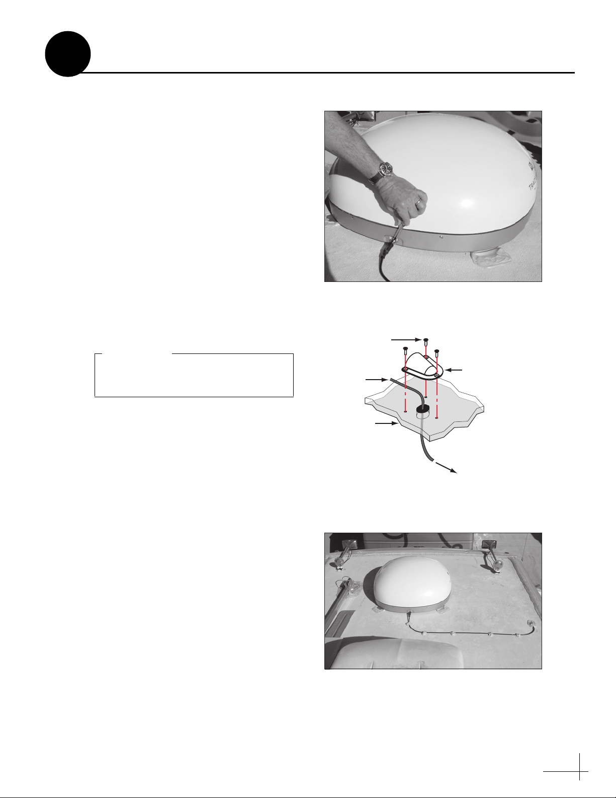
Wire the Antenna
a. At the location you chose earlier, use a
5/8" hole saw to cut out a cable access
hole in the vehicle’s roof. Smooth the
edges of the hole to protect the cable.
b. Connect the RG6 antenna cable (the end
with the rubber sealing boot) to the
antenna. Hand-tighten, then tighten with
a 7/16" wrench for 1/4 turn (see
Figure 10).
c. Slide the rubber sealing boot up the cable
until it covers the connector. This boot
will help protect the connector from the
elements.
d. Route the other end of the antenna cable
down through the roof access hole and
into the vehicle. Later, you will connect
this end of the cable to the receiver.
IMPORTANT!
Do not kink the cable. Maintain a
bend radius of at least 3 inches.
Figure 10 Antenna Cable with Rubber Sealing Boot
Figure 11 Clamshell Ventilator Mounting
Fasteners
(not supplied)
Antenna
Cable
Clamshell
Ventilator
e. Leave an adequate service loop -
approximately 8" of slack - in the antenna
cable for easy serviceability.
f. Seal the cable access hole with a liberal
amount of silicone sealant (or equivalent)
to protect against leakage.
g. Install the clamshell ventilator over the
cable access hole. The clamshell’s opening
should face the rear of the vehicle. Secure
in place with appropriate fasteners (see
Figure 11).
Vehicle
Roof
To Receiver
Figure 12 Antenna Installed
7
Page 7

6
Wire the Receiver
a. If you cut the antenna cable, use an Augat
IT1000 tool to attach a Snap-N-Seal
®
F-connector to the end of the connector
(see Figure 13).
IMPORTANT!
Do not use a screw-on, push-on, or
twist-on connector. Low-quality
connectors will degrade the system
performance and KVH’s warranty
does not cover repairs resulting from
the use of such connectors.
b. Connect the antenna cable (A) to the “To
KVH Antenna” jack (see Figure 14).
c. Connect the RF converter cable (B) to the
“RF Remote Input” jack.
d. Connect the receiver to the TV’s video
input. Choose one of the following
options:
Option 1 - RCA-type jack (cable included)
Option 2 - S-Video jack
Figure 13 Augat Tool
Figure 14 Receiver Wiring
(A)
Roof
e. Connect the receiver to the TV’s audio
input. Choose one of the following
options:
Option 1 - RCA-type jacks (cables
included)
Option 2 - Digital audio jack
NOTE: For details on connecting additional
receivers, refer to the User’s Guide.
NOTE: If the TV has only a coaxial input,
you will need an RF modulator (KVH
P/N 19-0475).
Receiver
To Video
(Option 2)
To Video
(Option 1)
Tested to comply
with FCC Standards
VIDEO AUDIO L AUDIO R
S-VIDEO
Y
RW
To Audio
(Option 1)
REMOTE
INPUT
RF
(B)
CAUTION
DIGITAL
AUDIO
110W/HD
OUT
CONVERTER
RF Converter
TO
TO KVH
ANTENNA
To Audio
(Option 2)
8
Page 8

7
Connect Power
The receiver requires 10-16 volts DC (VDC)
power input supporting 60 watts (5 amps @
12VDC).
CAUTION
For your own safety, shut down vehicle
power before you connect the wires.
a. Before you connect the power wires, turn
off vehicle power and test the circuit to
ensure no power is present.
b. Connect the individual power wires to a
dedicated 12 VDC circuit. Connect the
negative (black) wire to ground (power
return), and connect the positive (red)
wire to clean +12 VDC vehicle power.
NOTE: If vehicle power fluctuates or is noisy,
KVH recommends that you use an AC/DC
power supply (KVH P/N 72-0206-01) to
provide stable power to the receiver.
Figure 15 Receiver Power Wiring
Black
Red
Receiver
Ground
Input Power
(10-16 VDC)
c. Plug the other end of the wires into the
“Vehicle Power” jack on the rear panel of
the receiver (see Figure 15).
9
Page 9

8
Mount the Receiver
a. If you wish to mount the receiver, attach
the two mounting brackets to the sides of
the unit using three #2-56 screws. Simply
screw these fasteners into the vent slots
(see Figure 16).
IMPORTANT!
To avoid overheating, do not block
the upper vents of the receiver.
b. If you are using the mounting brackets,
secure the brackets to the mounting
surface using appropriate 1/4" fasteners
(not supplied).
NOTE: Be sure to leave enough slack in the
connecting cables (service loop) for easy
serviceability.
c. Place the RF converter at least 3 feet away
from the receiver. If it is too close to the
receiver, the remote control might not
operate properly. Also avoid placing the
RF converter behind a metal surface or in
an area surrounded by metal.
Figure 16 Receiver Brackets
1⁄4" Fasteners (x4)
(not supplied)
#2-56 x 1⁄4"
Screws (x3)
Bracket
Figure 17 RF Converter
Figure 18 Remote Batteries
d. If desired, mount the RF converter using
the supplied Velcro fasteners.
e. Insert two AAA batteries (supplied in the
kit) in the remote control’s battery
compartment (see Figure 18).
AAA Batteries
10
Page 10
9
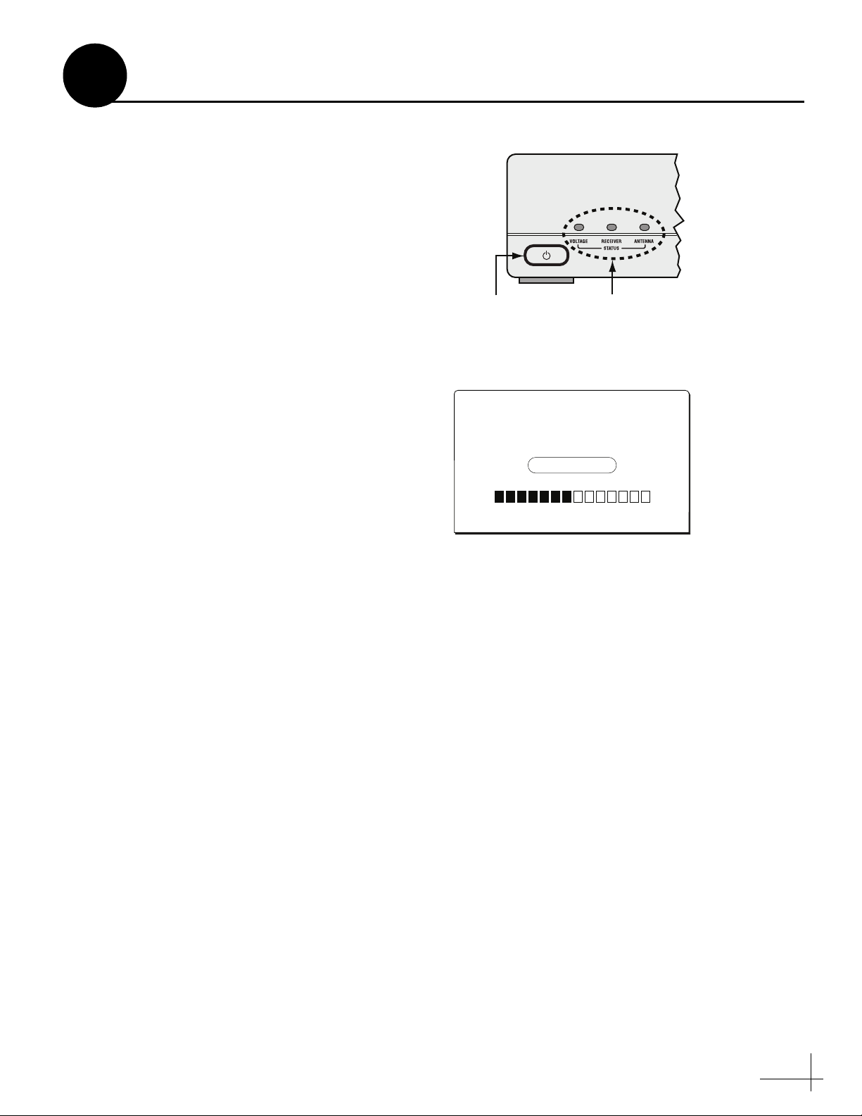
Test the System
Now that you have installed the TracVision R6ST
system, you need to turn the system on and
verify that the antenna works properly.
a. Ensure the antenna has a clear view of the
southern sky.
b. Apply power to the TV, receiver, and the
TracVision R6ST system.
c. Turn on the power switch on the front of
the receiver (see Figure 19).
d. Wait while the antenna searches the sky
for the satellite. Within a few minutes, all
three status lights on the front of the
receiver should be lit green.
NOTE: If all three status lights are not lit
green, refer to the User’s Guide for
troubleshooting information.
e. A progress bar will appear on the TV,
indicating that the receiver is
downloading the program guide (see
Figure 20).
Figure 19 Receiver Status Lights
Power Switch
Figure 20 Program Guide Progress Bar
If your satellite dish is ready for DIRECTV
service, please wait until your
Advanced Program Guide™ is prepared.
Acquiring guide data...
Status Lights
Installation
®
NOTE: The receiver might take up to one
minute to load the program guide.
f. Once the program guide is loaded, verify
that you can view the DIRECTV preview
channel (channel 100).
11
Page 11

10
Educate the Customer
Be sure to give the manuals to the customer and
explain how to use the product. The customer
also needs to know the following:
• Keep the radome installed on the antenna at
all times. The radome protects the antenna’s
internal moving parts from wind, rain, and
debris.
• The owner needs the red Activation Card to
activate the receiver. The receiver must be
activated before it can receive satellite
programming.
• The antenna must have a clear view of the
southern sky to receive satellite TV. Common
causes of blockage are trees, buildings,
bridges, overpasses, and mountains. The
TracVision R6ST system will not work inside
a garage.
• Heavy rain or snow might temporarily
interrupt reception.
Figure 21 Activation Card
XXXXXXXXX
Figure 22 Blockage Example
Blocked!
XXXXXXXXX
• To ensure optimum reception, keep
DewShield
electronic dew elimination system prevents
dew from forming on the antenna (moisture
weakens satellite signals).
• The antenna should be cleaned regularly. Dirt
buildup on the radome can affect satellite TV
reception.
• The owner needs to register the system for
product warranty validation. Refer to the
Product Registration Form for details or visit:
www.kvh.com/register.
• The vehicle must be located within the
selected satellite’s coverage area in order to
receive its satellite TV signals. To view
satellite coverage maps, visit: www.kvh.com/
footprint.
• Refer to the User’s Guide for complete
operation instructions.
™
set to AUTO. The DewShield
12
 Loading...