

Page 1
TracVision® R1ST
with 12V DIRECTV® Mobile Receiver
TracVision R1ST Installation Guide
Page 2

TracVision R1ST Installation Guide
DIRECTV® Mobile Receiver Configuration
These instructions explain how to install the TracVision R1ST satellite TV antenna system on a
vehicle. Complete instructions on how to use the system are provided in the User’s Guide.
Installation Steps
1. Inspect Parts and Get Tools ...............3
2. Plan the Installation.............................4
3. Prepare the Antenna ...........................5
4. Wire the Antenna ................................6
5. Mount the Antenna .............................7
6. Wire the Receiver.................................8
7. Connect Power.....................................9
8. Mount the Receiver ...........................10
9. Test the System ..................................11
10. Educate the Customer.......................12
Who Should Install the System?
To ensure a safe and effective installation, KVH recommends that a KVH-authorized technician
install the TracVision R1ST antenna. To find a technician near you, please visit www.kvh.com/
wheretogetservice.
Related Documentation
The following additional documents are provided with the TracVision R1ST system:
Document
User’s Guide Complete operation, setup, and troubleshooting
Description
information
Quick Start Guide Handy quick reference to basic operation and
troubleshooting information
Product Registration Form Details on registering the product with KVH
Warranty Statement Warranty terms and conditions
Contents List List of every part supplied in the kit
Technical Support
If you need technical assistance, please contact KVH Technical Support:
Phone: +1 401 847-3327
E-mail: techs@kvh.com
(Mon.-Fri., 9 am-6 pm ET; Sat. 9 am-2 pm ET)
KVH, TracVision, and the unique light-colored dome with dark contrasting baseplate are registered trademarks of KVH Industries, Inc.
All other trademarks are property of their respective companies. The information in this document is subject to change without notice.
No company shall be liable for errors contained herein. © 2011 KVH Industries, Inc., All rights reserved. 54-0805 Rev. A
1
Page 3
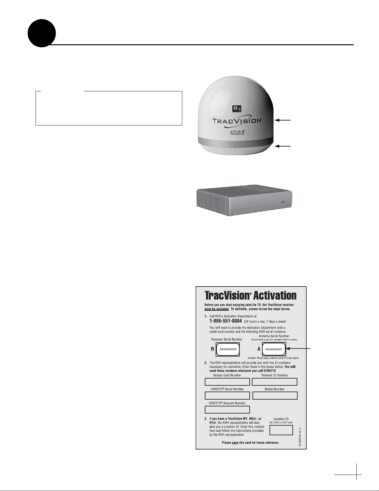
Always lift the antenna by the baseplate and
never by the radome or any portion of the
internal antenna assembly (see Figure 1).
IMPORTANT!
Figure 1: TracVision R1ST System Components
Mobile Receiver/Controller
Affix Serial
Number Here
Figure 2: Activation Card
1
Before you begin, follow these steps to make sure
you have everything you need to complete the
installation.
a. Unpack the box and ensure it contains
everything shown on the Kitpack Contents
List. Save the packaging for future use.
b. Carefully examine all of the supplied parts to
ensure nothing was damaged in shipment.
c. Gather all of the tools and materials listed
below. You will need these items to complete
the installation.
• #2 Phillips screwdriver
Inspect Parts and Get Tools
Antenna
Radome
Baseplate
• 7/16" open-end wrench
• Cutting pliers
• Silicone sealant, RTV, or equivalent
• Construction adhesive suitable for the
roof
• Fasteners suitable for mounting the
antenna to the roof
• 5/8"- diameter hole saw
• Augat IT1000 connector installation tool
(KVH part #19-0242)
• Eight 1/4" fasteners (see “Mount the
Receiver” on page 10)
• RF modulator (if necessary, see “Wire the
Receiver” on page 8)
d. Peel off the extra serial number label (taped
to the antenna) and affix it in the appropriate
box on the red Activation Card (see Figure 2).
3
Page 4
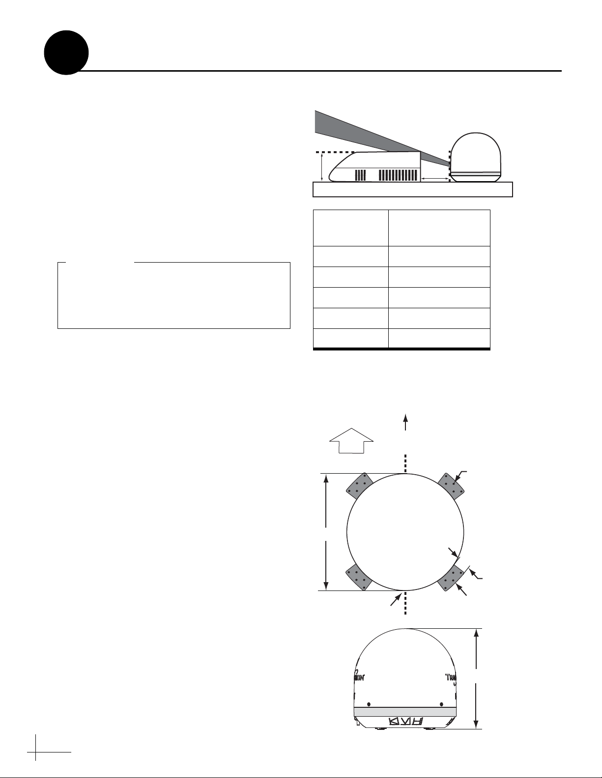
Figure 3: Blockage from Obstruction
Obstruction
Height (A)
Min. Distance
from Antenna (B)
8" 19.5"
10" 26"
12" 32.5"
14" 39"
16" 45.5"
When placed on the mounting surface, all
four mounting plates must lay flat against the
roof (within 7/16") to avoid warping the base
and damaging the antenna.
IMPORTANT!
Cable Connector
FWD
Antenna
(Top View)
Antenna
(Side View)
13.13"
Antenna
(Top View)
Ø13.5"
1.5"
Mounting
Plate
5 x Ø0.19"
Front of Vehicle
Vehicle
Centerline
Figure 4: Antenna Dimensions
2
Plan the Installation
Before you begin, consider the following
installation guidelines:
• Minimize blockage. The antenna requires a
clear view of the southern sky to receive
satellite TV. Using the guidelines in Figure 3
as a guide, mount the antenna a suitable
distance away from obstructions on the roof,
such as air conditioners.
• Ensure the mounting surface is flat and
strong enough to support the antenna’s
weight (7.5 lbs).
• Select an antenna mounting location on the
centerline of the vehicle with the antenna’s
cable connector facing the rear of the vehicle
(see Figure 4).
NOTE: A template showing the exact locations of the
antenna mounting holes and the dimensions between
them is provided in the Welcome Kit.
Blocked!
A
Vehicle Roof
Obstruction
Antenna
B
• Be sure to mount the antenna near enough to
the receiver to allow you to connect the 50-ft.
coax cable between them, while still
maintaining sufficient slack in the cable.
NOTE: If you need to use a longer cable, use an RG6
(75 ohms) cable that does not exceed 80 feet in length.
• Once you’ve chosen a location for the
antenna, identify a safe location nearby for
the 5/8" cable access hole in the roof. It
should be located at least 6" away from the
connector. Make sure you will not drill into
any existing wires or aesthetic structures
inside the vehicle.
• When choosing a location for the receiver,
find a dry, well-ventilated area inside the
vehicle away from any heat sources. Also be
sure the front panel of the receiver will be
4
easily accessible to the user.
Page 5

Figure 5: Attaching the Mounting Plates
3
Follow these steps to attach the four mounting
plates to the antenna’s baseplate.
a. Attach the four supplied metal mounting
plates to the bottom of the antenna using the
eight M5 screws supplied in the kitpack (see
Figure 5).
b. Over each mounting plate, fit a supplied
rubber bumper into the hole in the antenna’s
baseplate (see Figure 5).
c. Carefully carry the antenna to the roof of the
vehicle.
Prepare the Antenna
Mounting Plate (x4)
M5 Screw (x8)
Rubber Bumper (x4)
5
Page 6

Do not kink the cable. Maintain a bend radius
of at least 3 inches.
IMPORTANT!
Figure 6: Connecting the Antenna Cable
Figure 7: Mounting the Clamshell Ventilator
4
Follow these steps to connect the antenna cable to
the antenna.
a. At the location you chose in Step 2 on page 4,
use a 5/8" hole saw to cut out a cable access
hole in the vehicle’s roof. Smooth the edges of
the hole to protect the cable.
b. Route the RG6 antenna cable (the end with
the straight connector) down through the
cable access hole and into the vehicle. You
may remove the straight rubber boot for
easier cable routing. Later, you will connect
this end of the cable to the receiver.
c. Connect the RG6 antenna cable (the end with
the right-angle connector and rubber sealing
boot) to the antenna. Hand-tighten, then
tighten with a 7/16" wrench for 1/4 turn to
ensure an electrical and weather-proof
connection (see Figure 6).
Wire the Antenna
d. Position the rubber boot over the connector to
help protect the connector from the elements.
e. Leave an adequate service loop,
approximately 8" of slack, in the antenna
cable for easy serviceability.
f. Seal the cable access hole with a liberal
amount of silicone sealant (or equivalent) to
protect against leakage.
g. Install the supplied clamshell ventilator over
the cable access hole. The clamshell’s opening
should face the rear of the vehicle. Secure in
place with the three #6 screws supplied in the
kitpack (see Figure 7). Then seal the screws
with silicone sealant (or equivalent).
#6 Screw (x3)
Antenna
Cable
Vehicle
Roof
Clamshell
Ventilator
To Receiver
6
Page 7

Due to the variation in RV roof construction,
consult with the RV manufacturer to
determine the safest fastening method.
IMPORTANT!
Cable Connector
Antenna
(Top View)
Antenna
(Top View)
Mounting
Plate (x4)
Ø0.19" Mounting
Hole (x20)
Front of Vehicle
Vehicle
Centerline
Figure 8: Mounting the Antenna
5
Follow these steps to mount the antenna to the
roof.
a. Apply appropriate construction adhesive to
the bottom of the antenna’s four mounting
plates across all of the holes.
b. At the mounting location you chose in Step 2
on page 4, place the antenna on the centerline
of the roof so that the cable connector faces
the rear of the vehicle (see Figure 8).
c. Attach the four antenna mounting plates to
the roof using 20 fasteners appropriate for the
roof’s construction (see Figure 8).
Mount the Antenna
d. Seal all fasteners with silicone sealant (or
equivalent).
7
Page 8
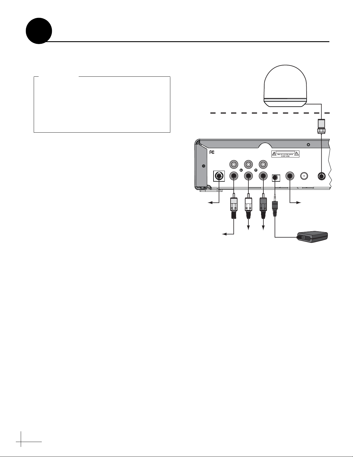
If you cut the antenna cable, terminate the
cable with a Snap-N-Seal
®
F-connector using
an Augat IT1000 tool. Low-quality connectors
will degrade system performance and KVH’s
warranty does not cover repairs resulting
from the use of such connectors.
IMPORTANT!
(A)
Roof
CAUTION
S-VIDEO
VIDEO AUDIO L AUDIO R
RF
REMOTE
INPUT
DIGITAL
AUDIO
OUT
TO
110W/HD
CONVERTER
TO KVH
ANTENNA
Tested to comply
with FCC Standards
RF Converter
Receiver
To A udio
(Option 1)
To Video
(Option 1)
To Video
(Option 2)
To A udio
(Option 2)
Y
RW
(B)
Antenna
Figure 9: Wiring the Receiver
6
Wire the Receiver
Follow these steps to connect system cables to the
receiver.
a. Connect the antenna cable (A) to the “To
KVH Antenna” jack (see Figure 9).
b. Connect the RF converter cable (B) to the “RF
Remote Input” jack.
c. Connect the receiver to the TV’s video input.
Choose one of the following options:
Option 1 - RCA-type jack (cable included)
Option 2 - S-Video jack
NOTE: If the TV has only a coaxial input, you will
need an RF modulator (KVH part #72-0292).
d. Connect the receiver to the TV’s audio input.
Choose one of the following options:
Option 1 - RCA-type jacks (cables included)
Option 2 - Digital audio jack
NOTE: For details on connecting additional receivers,
refer to Appendix A of the User’s Guide.
8
Page 9

CAUTION
For your own safety, shut down vehicle
power before you connect the wires.
Ground
Input Power
(10-16 VDC)
Red
Black
Powe r
Figure 10: Receiver Power Wiring
7
The receiver requires 10-16 VDC power input
supporting 50 watts (4.2 amps @ 12 VDC). Follow
these steps to connect power to the receiver.
a. Before you connect the power wires, turn off
vehicle power and test the circuit to ensure
no power is present.
b. Connect the individual power wires to a
dedicated 12 VDC circuit. Connect the
negative (black) wire to ground (power
return), and connect the positive (red) wire to
clean +12 VDC vehicle power.
NOTE: If vehicle power fluctuates or is noisy, KVH
recommends that you use an AC/DC power supply
(KVH part #72-0206-01) to provide stable power to
the receiver.
Connect Power
c. Plug the other end of the wires into the
“Power” jack on the rear panel of the receiver
(see Figure 10).
9
Page 10

Bracket
#2-56 x 1⁄4"
Screws (x3)
1⁄4" Fasteners (x4)
(not supplied)
Figure 11: Receiver Mounting
To avoid overheating, do not block the upper
vents of the receiver.
IMPORTANT!
Figure 12: RF Converter
Figure 13: Remote Control Batteries
8
Once all cables are connected, follow these steps
to install the receiver inside the vehicle.
a. Attach the two mounting brackets to the
sides of the unit using three #2-56 screws.
Simply screw these fasteners into the vent
slots (see Figure 11).
b. Secure the brackets to the mounting surface
using appropriate 1/4" fasteners (not
supplied).
NOTE: Be sure to leave enough slack in the
connecting cables (service loop) for easy serviceability.
c. Place the RF converter at least 3 feet away
from the receiver (see Figure 12). If it is too
close to the receiver, the remote control might
not operate properly. Also avoid placing the
RF converter behind a metal surface or in an
area surrounded by metal.
Mount the Receiver
d. If desired, mount the RF converter using the
supplied Velcro fasteners.
e. Insert two AAA batteries (supplied in the
kitpack) in the remote control’s battery
compartment (see Figure 13).
AAA Batteries
10
Page 11

Figure 14: Receiver Power Switch and Status Lights
Figure 15: Program Guide Progress Bar
9
Now that you have installed the system, follow
these steps to turn the system on and verify that
the antenna works properly.
a. Ensure the antenna has a clear view of the
sky.
b. Apply power to the TV and the TracVision
system.
Test the System
c. Turn on the power switch on the front of the
receiver (see Figure 14).
d. Wait while the antenna searches the sky for
the DIRECTV satellite. Within a few minutes,
all three status lights on the front of the
receiver should be lit green (see Figure 14). If
all three status lights are not lit green, refer to
the User’s Guide for troubleshooting
information.
e. Wait one minute for the receiver to download
the program guide. A progress bar will
appear on the TV (see Figure 15).
f. Once the program guide is loaded, verify that
you can view the DIRECTV preview channel
(100).
Power Switch
Status Lights
11
Page 12

CAUTION
In the unlikely event that you need to
remove the radome, remove power from the
antenna first because the antenna’s moving
parts can cause injury.
WARNING
It is dangerous to watch TV while driving a
vehicle. While the vehicle is in motion, the
system is intended for passenger use only.
Figure 16: Activation Card
Figure 17: Blockage Example
10
Before you leave the vehicle, give the Customer
Welcome Kit, the red Activation Card, and all
manuals to the customer and explain how to use
the system. Also be sure the customer
understands the following:
• Keep the radome installed on the antenna at
all times. The radome protects the antenna’s
moving parts from wind, rain, and debris.
Educate the Customer
• The receiver must be activated first before it
can decode satellite TV signals. Refer to the
red Activation Card for details (see
Figure 16).
• The antenna must have a clear view of the
sky to receive satellite TV. Common causes of
blockage include trees, buildings, bridges,
and mountains (see Figure 17). The
TracVision system will not work inside a
garage. Heavy rain or snow might also
temporarily interrupt reception.
• Clean the antenna regularly. Dirt buildup on
the radome can affect satellite TV reception.
• Please register the system with KVH. The
registration process is quick, easy, online, and
ensures the best possible service from KVH.
Visit www.kvh.com/register or refer to the
Product Registration Form for details.
Blocked!
• The vehicle must be located within the
selected satellite’s coverage area. To view
satellite coverage maps, visit: www.kvh.com/
footprint.
12
Page 13

www.kvh.com
KVH Industries, Inc.
World Headquarters
Middletown, RI U.S.A.
Tel: +1 401 847 3327 Fax: +1 401 849 0045
E-mail: info@kvh.com
KVH Europe A/S
EMEA Headquarters
Kokkedal, Denmark
Tel: +45 45 160 180 Fax: +45 45 160 181
E-mail: info@emea.kvh.com
KVH Singapore
Asian Headquarters
Singapore
Tel: +65 6513 0290 Fax: +65 6472 3469
E-mail: info@asia.kvh.com
KVH Norway AS
Horten, Norway
Tel: +47 33 03 05 30 Fax: +47 33 03 05 31
E-mail: info@no.kvh.com
 Loading...