

Page 1

TracVision M7 Installation Guide
TracVision M7
GyroTrac™Configuration
Page 2

TracVision® M7 Installation Guide
GyroTrac Configuration
These instructions explain how to install the TracVision M7 satellite TV antenna system on a
vessel. Complete instructions on how to use the system are provided in the User’s Guide.
Installation Steps
1. Inspect Parts and Get Tools ................. 3
2. Plan the Antenna Installation.............. 4
3. Plan the Sensor Installation.................. 5
4. Plan the ADCU Installation ................. 6
5. Prepare the Antenna Site...................... 7
6. Remove the Restraint............................ 8
7. Wire the Antenna .................................. 9
8. Mount the Antenna............................. 10
9. Mount the Sensor................................. 11
10. Wire the Receiver(s)............................ 13
11. Wire the ADCU....................................15
12. Connect Power .....................................16
13. Mount the ADCU.................................17
14. Select Satellites......................................18
15. Enter Your Latitude & Longitude ..... 21
16. Get the LNB Skew Angle....................22
17. Set the LNB Skew Angle.....................23
18. Run Check Switch Tests......................24
19. Calibrate the Sensor.............................26
20. Educate the Customer.........................28
Who Should Install the System?
To ensure a safe and effective installation, KVH recommends that a KVH-authorized marine
technician install the TracVision antenna. KVH-authorized technicians have the tools and
electronics expertise necessary to instal l the system. To find a technician near you, visit
www.kvh.com/wheretogetservice.
Linear vs. Circular Systems
The installation process differs slightly depending on the type of LNB (low noise block) that is
installed in the antenna (linear or circular). These differences are noted throughout this manual.
Technical Support
If you need technical assistance, please contact KVH Technical Support:
North/South America, Australia:
Phone: +1 401 847-3327
E-mail: techs@kvh.com
(Mon.-Fri., 9 am-6 pm ET, -5 GMT)
(Sat., 9 am-2 pm ET, -5 GMT)
KVH, TracVision, and the unique light-colored dome with dark contrasting baseplate are registered trademarks of KVH Industries, Inc.
All other trademarks are property of their respective companies. The information in this document is subject to change without notice.
No company shall be liable for errors contained herein. © 2007-2011 KVH Industries, Inc., All rights reserved. 54-0417-01 Rev. D
Europe, Middle East, Asia:
Phone: +45 45 160 180
E-mail: support@kvh.dk
(Mon.-Fri., 8 am-4:30 pm, +1 GMT)
1
Page 3

Figure 1: TracVision M7 System Components
Antenna
GyroTrac Sensor
ADCU (Advanced Digital Control Unit)
Radome
Baseplate
Always lift the antenna by the baseplate and
never by the radome or any portion of the
internal antenna assembly (see Figure 1).
IMPORTANT!
Figure 2: Guidelines for Power Cable
Cable Length Use Cable Gauge
< 40 ft (12 m)
14AWG (2.5mm
2
)
40-70 ft (12-21 m)
12AWG (4mm
2
)
Figure 3: KVH-Validated U.S./Canadian Receivers
Standard-Definition Models
DIRECTV DISH Network Bell TV
D12
D11
D10
311
211k
211
4100
3100
High-Definition (HD) Models
DIRECTV DISH Network Bell TV
HD not
supported
211k
211
6100
6131
1
Before you begin, follow these steps to make sure
you have everything you need to complete the
installation.
a. Unpack the box and ensure it contains
everything shown on the Kitpack Contents
List. Save the packaging for future use.
b. Carefully examine all of the supplied parts to
ensure nothing was damaged in shipment.
c. Gather all of the tools and materials listed
below. You will need these items to complete
the installation.
• Flat-head and Phillips-head screwdrivers
Inspect Parts and Get Tools
• Electric drill and 1/2" (13 mm), 1/8"
(3.5 mm), and #29 drill bits
• 3" (80 mm) hole saw
• Socket wrenches and 7/16" open-end
wrench
• Torque wrench and 2 mm allen hex key
(only required for linear systems without
Auto Skew capability)
• Light hammer and center punch
• Adhesive tape and scriber or pencil
• Wire strippers and terminal lug crimper
• RG-6 or RG-11 RF coax cable(s) with
Snap-N-Seal
• Augat IT1000 connector installation tool
• Power cable (see Figure 2)
• Silicone sealant, self-vulcanizing tape, or
equivalent
• Satellite TV receiver and TV (see Figure 3
for a list of validated U.S./Canadian receivers)
• If you need to configure the system for
Tri-Sat mode: Windows
Windows HyperTerminal (or equivalent)
or KVH Flash Update Wizard installed
®
F-connectors (see Step 7a)
®
laptop PC with
3
Page 4
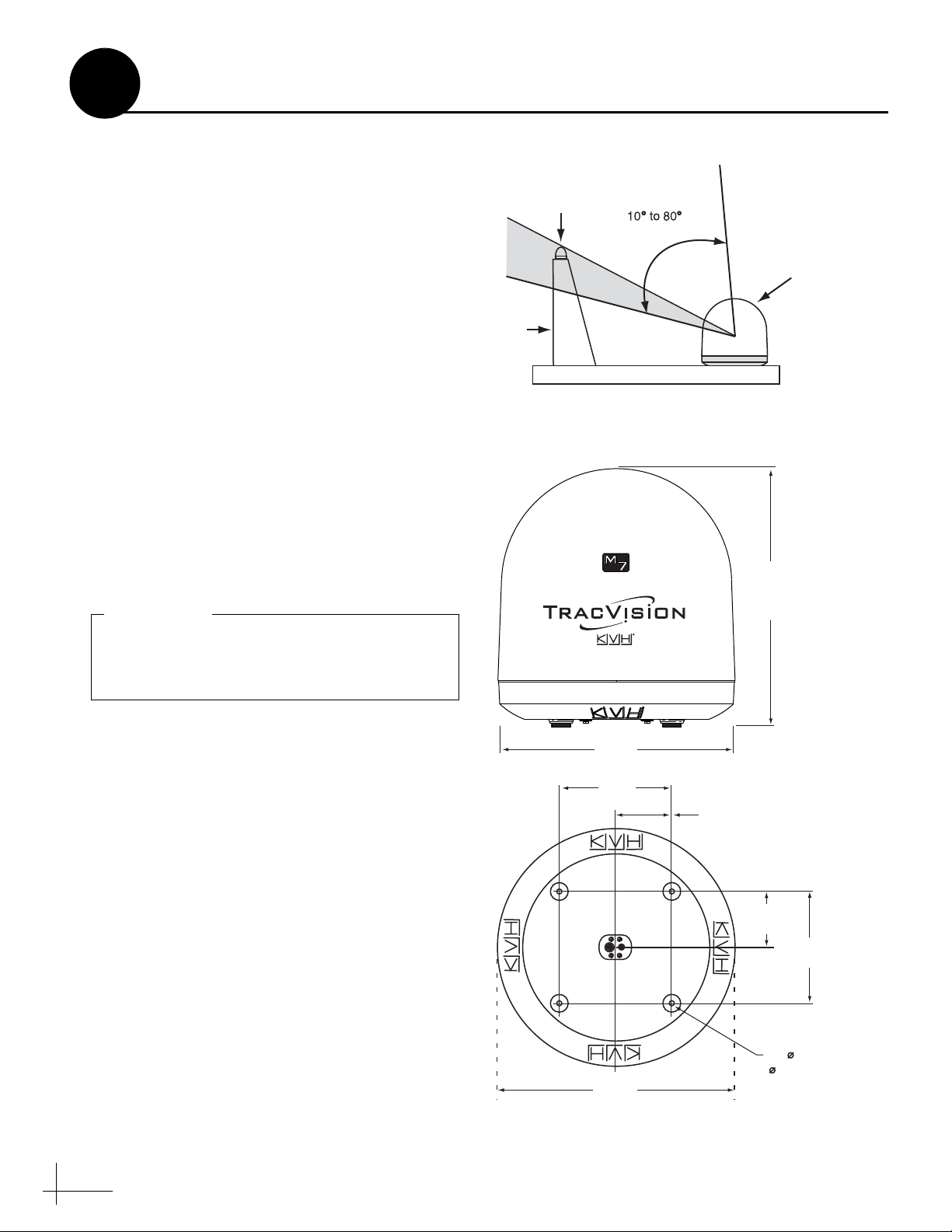
Blocked!
TracVision Antenna
Mast
Look Angle
Vessel Platform
Figure 4: Blockage from Obstruction
27.36"
(69.5 cm)
26.2"
(66.5 cm)
12"
(30.5 cm)
12"
(30.5 cm)
6"
(15.2 cm)
6"
(15.2 cm)
4 x 1/2"
( 13 mm)
26.2"
(66.5 cm)
Figure 5: Antenna Dimensions
Side View
Bottom View
Be sure to follow the guidelines above.
Damage caused by an improper installation is
not covered under KVH warranty.
IMPORTANT!
2
Plan the Antenna Installation
Consider the following antenna installation
guidelines:
• Minimize blockage. The antenna requires a
clear view of the sky to receive satellite TV
(see Figure 4). The fewer obstructions, the
better the system will perform.
• Make sure the mounting surface is wide
enough to accommodate the antenna’s base
(see Figure 5). Also make sure it is flat, level
(within ±1°), strong enough to support the
antenna’s weight (55 lbs, 25 kg), and rigid
enough to withstand vibration.
• Select a location that is as close as possible to
the intersection of the vessel’s fore-and-aft
centerline and midships.
• Do not mount the antenna at the same level
as the radar because the radar’s energy might
overload the antenna. Ideally, you should
mount the antenna 4 ft (1.2 m) above the
radar, outside the beam path of the radar.
4
Page 5
5"
(12.7 cm)
7.8"
(19.8 cm)
5"
(12.7 cm)
Figure 6: GyroTrac Sensor
3
Consider the following GyroTrac sensor
installation guidelines:
• Select a sensor mounting location in a dry
area belowdecks as low as possible in the
center of the vessel. Do not mount the sensor
in a bilge.
• Make sure the mounting surface does not flex
and is rigid enough to withstand vibration.
• Select a location that is at least 4 ft (1.2 m)
away from any magnetized materials, large
ferrous masses, cranes, derricks, antennas,
devices with DC motors, CRT monitors,
loudspeakers, electric winches, highamperage cables, or battery ban ks. The sensor
performs best in a benign magnetic
environment.
• If you need to fabricate custom mounting
brackets, be sure to make them from a nonferrous material, such as wood, brass,
aluminum, fiberglass, or plastic. Also be sure
to use stainless steel bolts or nails.
Plan the Sensor Installation
• If you are mounting the sensor on a steel
vessel, enclose the sensor in a fiberglass
container and use an aluminum, brass,
plastic, or wood platform (NOT steel or iron)
to position the sensor at least 4 ft (1.2 m)
above and 6 ft (1.8 m) away from the steel
surface.
5
Page 6
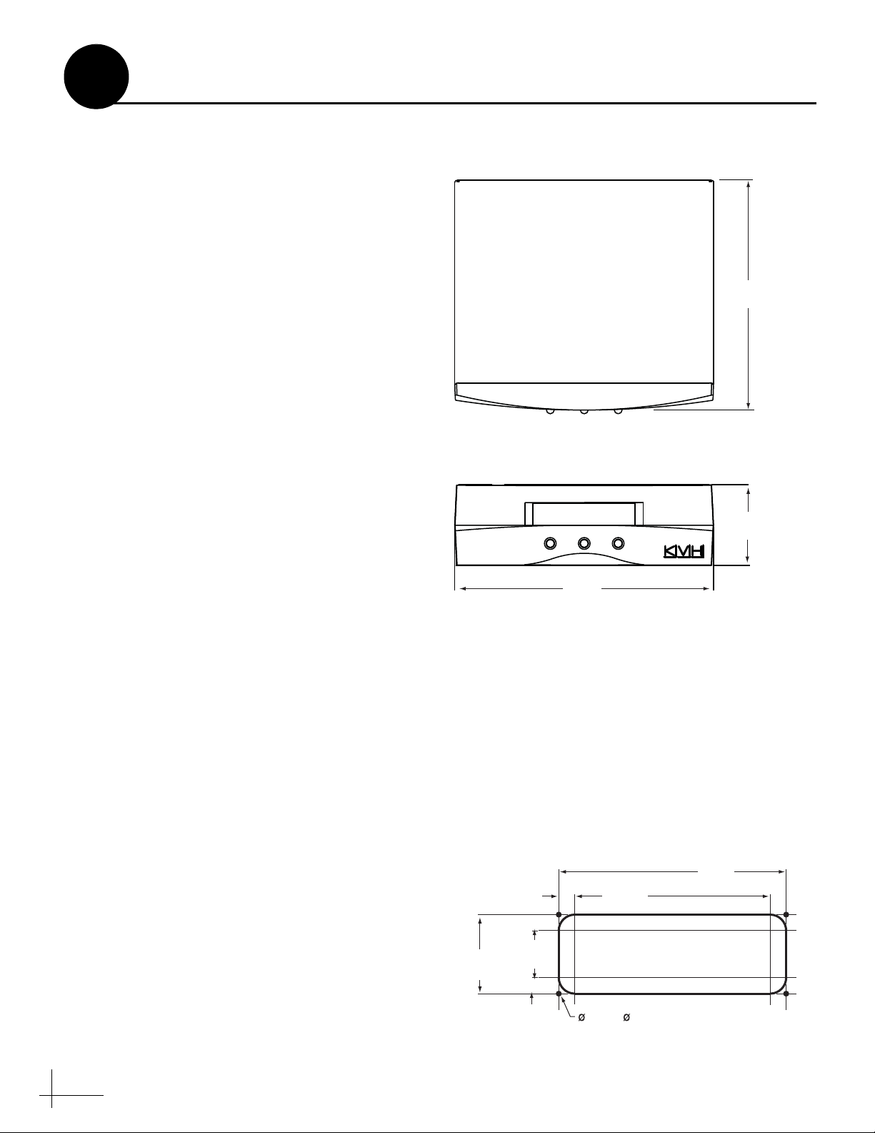
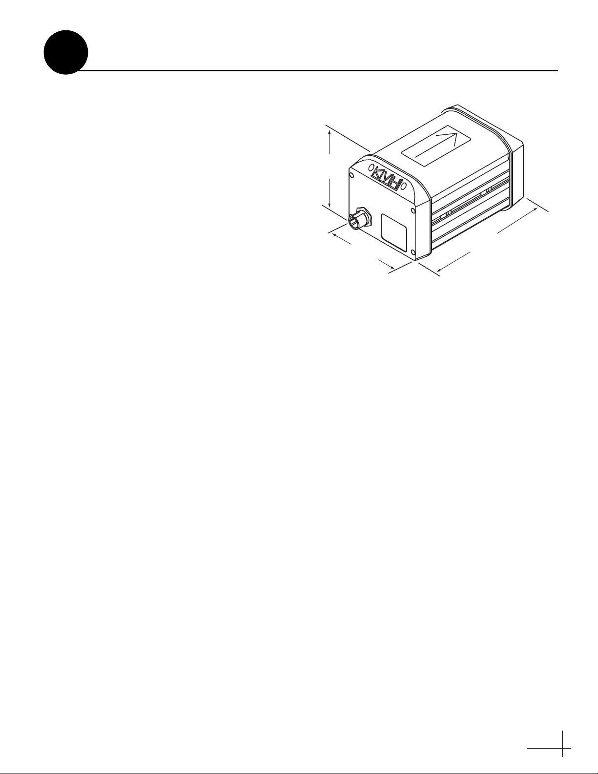
Figure 7: ADCU Dimensions
Front View
Top View
Figure 8: ADCU Mounting Holes Layout
4
Plan the ADCU Installation
Consider the following ADCU installation
guidelines:
• Select an ADCU mounting location in a dry,
well-ventilated area belowdecks, away from
any heat sources or salt spray.
• Be sure the ADCU’s front panel will be easily
accessible to the user.
• Be sure to leave enough room at the ADCU’s
rear panel for connecting the cables (see
Figure 7 for ADCU dimensions).
• Consider the lengths of the connecting cables.
The ADCU must be located close enough to
the antenna and the GyroTrac sensor so that
you can connect the supplied cables, while
allowing adequate slack for a service loop.
The antenna data cable is 100 ft (30 m); the
GyroTrac sensor cable is 30 ft (9 m).
7.3"
(18.5 cm)
• (Circular and Sky Mexico only) The
grounding block should be located within
95 ft (28 m) of the antenna, within 5 ft (1.5 m)
of the primary receiver, and within 25 ft
(7.6 m) of a suitable vessel AC ground.
• The kitpack contains parts for mounting the
ADCU either to a horizontal surface (using
Velcro) or to a vertical surface (using the
supplied flush mount bracket).
Prepare the ADCU Mounting Site
(Flush Mount only)
NOTE: Skip this step if you plan to mount the ADCU
to a horizontal surface instead; proceed to page 7.
a. Using the ADCU flush mounting template
provided at the end of this manual, mark and
cut out a hole in the mounting surface to
accommodate the flush mount bracket (see
Figure 8).
b. Using the same template, mark the locations
for the four ADCU mounting holes.
c. Using a #29 drill bit, drill a 0.136" (3.45 mm)
hole at the four mounting hole locations.
Later, you will mount the ADCU using four
#8 screws.
3.08"
(78 mm)
.63"
(16 mm)
1.83"
(46 mm)
.63"
(16 mm)
8.2"
(20.8 cm)
7.62"
(194 mm)
.136" ( 3.45 mm)
Mounting Hole (x4)
2.6"
(6.6 cm)
8.87"
(225 mm)
6
Page 7

Figure 9: Antenna Mounting Holes Layout
Figure 10: Foam Seal
Align with
Cable Access
Hole
5
Once you have identified a suitable antenna
mounting site, according to the guidelines
provided on page 4, follow these steps to drill the
mounting holes and cable access hole to prepare
the site for installation.
Prepare the Antenna Site
FWD
a. Unfold the antenna mounting template
(supplied in the Customer Welcome Kit) and
place it onto the mounting surface. Make sure
the “FWD” (forward) arrow points toward
the bow and is parallel to the vessel’s
centerline (see Figure 9).
NOTE: You don’t need to mount the antenna exactly
on the vessel’s centerline (the closer, the better), but
the antenna’s forward arrow must be parallel to it.
b. Using a light hammer and center punch,
mark the locations for the four mounting
holes and cable access hole on the mounting
surface in the locations indicated on the
template.
c. Drill a 1/2" (13 mm) hole at the four
mounting hole locations you marked in
Step b. Later, you will insert four 3/8"-16
bolts through these holes to secure the
antenna to the mounting surface.
d. Cut out the 3" (80 mm) cable access hole in
the location you marked in Step b. Smooth
the edges of the hole to protect the cables.
Later, you will route the data, power, and RF
cables through this hole and into the vessel.
(305 mm)
1/2" ( 13 mm)
Mounting Hole (x4)
3" ( 80 mm)
Cable Access Hole
12"
12"
(305 mm)
e. Clean and dry the antenna mounting surface.
f. Peel off the paper backing from the supplied
foam seal to expose the adhesive. Then press
the foam seal down firmly onto the mounting
surface, ensuring the hole in the foam seal
aligns with the cable access hole in the
mounting surface (see Figure 10).
NOTE: Apply the foam seal to the vessel mounting
surface, not to the antenna’s baseplate. You will have
difficulty connecting the cables to the antenna if the
foam seal is attached to the baseplate.
7
Page 8
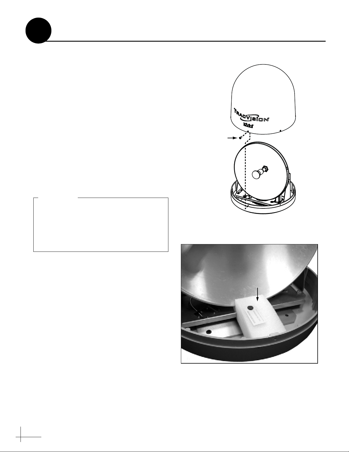
Figure 11: Removing the Radome
Figure 12: Foam Block Shipping Restraint
Shipping Restraint
Once you have removed the restraint, keep
the antenna level as much as possible and
handle the antenna very carefully. Prevent
the internal antenna assembly from rotating
freely within the baseplate to avoid damaging
the limit switch.
IMPORTANT!
6
Inside the antenna, a foam block prevents the
antenna assembly from moving during
shipment. Follow these steps to remove this
shipping restraint.
a. Remove the six #10-32 Phillips screws
securing the radome to the baseplate (see
Figure 11). Carefully lift the radome straight
up until clear of the antenna assembly and set
it aside in a safe place.
TIP: If you keep the radome topside, secure it with a
lanyard to prevent it from falling overboard.
b. Remove the foam block that is wedged
beneath the antenna’s reflector (see
Figure 12). Save this restraint for future use;
the customer will need to reinstall it if he/she
needs to relocate or reship the antenna.
Remove the Restraint
#10-32 Screw (x6)
8
Page 9
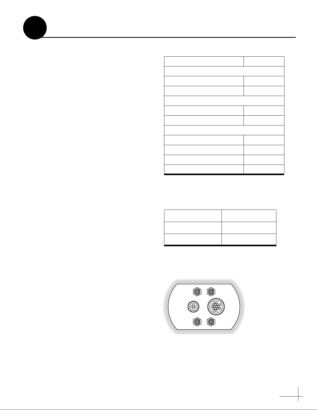
Figure 13: Number of RF Coax Cables to Connect to Antenna
* Multiswitch required for additional receivers.
Connecting to: # RF Cables
System with Circular Dual LNB
1 receiver 1
2 or more receivers 2*
System with Linear Dual LNB
1 receiver 1
2 receivers 2
System with Linear Quad LNB
1 receiver 1
2 receivers 2
3 receivers 3
4 or more receivers 4*
Figure 14: RF Cable Guidelines
Cable Length Use Cable Type
<= 75 ft (23 m) RG-6
> 75 ft (23 m) RG-11
Figure 15: Connectors on Bottom of Antenna
7
Follow these steps to connect the data, power,
and RF cables to the antenna.
a. First determine the number of RF coax cables
you need to connect to the antenna for your
particular installation (see Figure 13). (See
Figure 14 to determine the type of cable
required.)
b. Route the data, power, and RF cables
belowdecks through the 3" (80 mm) cable
access hole. Leave an adequate service loop,
approximately 8" (20 cm) of slack, in the
cables for easy serviceability. Later, you will
connect the data cable to the ADCU, the
power cable to vessel power, and the RF
cable(s) to the receiver(s).
c. Connect the data cable to the “Data”
connector on the bottom of the antenna (see
Figure 15). Hand-tighten until the cable locks
in place; do not use excessive force.
Wire the Antenna
d. Connect the power cable to the “Power”
connector on the bottom of the antenna.
Hand-tighten until the cable locks in place;
do not use excessive force.
e. Connect the RF coax cable(s) to the antenna.
If you need to connect just one RF cable,
connect the cable to the “RF1” connector on
the bottom of the antenna. Hand-tighten,
then tighten with a 7/16" wrench for 1/4 turn
to ensure an electrical connection. Connect
any additional RF coax cables to the
antenna’s RF2, RF3, and RF4 connectors, in
that order.
TIP: If you connect two or more RF cables, label both
ends of each cable to match the connector. This will
make it easier to identify the cables later.
f. Seal the RF cable connections with silicone
sealant, self-vulcanizing tape, or equivalent.
Power
RF3
RF1
RF4
Data
RF2
9
Page 10
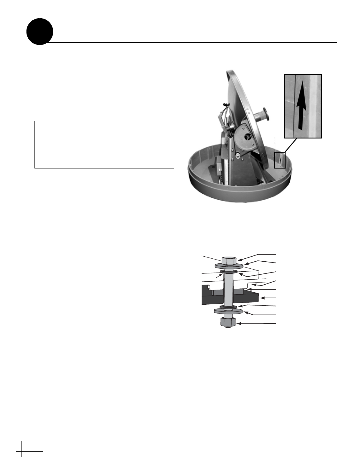
Figure 16: Forward Arrow in Antenna Baseplate
You will need to rotate the antenna assembly
by hand to see all four mounting holes. Rotate
the antenna assembly slowly. If it hits a
mechanical stop with excessive force, the
limit switch might become damaged.
IMPORTANT!
Figure 17: Mounting the Antenna (Side View)
3/8"-16 Bolt (x4)
3/8" Flat Washer (x4)
Rubber Foot (x4)
Mounting Surface
3/8" Flat Washer (x4)
3/8"-16 Lock Nut (x4)
Antenna Baseplate
3/8" Shoulder Washer (x4)
3/8" Shoulder Washer (x4)
Preinstalled
8
Follow these steps to mount the antenna to the
mounting surface.
a. Place the antenna baseplate over the holes
drilled in the mounting surface. Ensure the
forward arrow inside the baseplate points
toward the bow and is parallel to the vessel’s
centerline (see Figure 16).
b. At each of the four baseplate mounting holes,
place a 3/8" flat washer on a 3/8"-16 bolt and
insert the bolt into the hole (with preinstalled
3/8" shoulder washer) from above (see
Figure 17).
Mount the Antenna
NOTE: To enable proper grounding, ensure the
preinstalled shoulder washers are in place, and were
not dislodged during handling (see Figure 17).
c. Secure each mounting bolt to the mounting
surface using a 3/8" shoulder washer, a
3/8" flat washer, and a 3/8"-16 lock nut from
below. Tighten all four bolts until the four
rubber feet on the baseplate are bottomed
against the mounting surface and the foam
seal is fully compressed. KVH recommends
that you tighten the bolts to between 12 and
10
16 ft-lbs (16.2 and 21.7 N-m) of torque.
TIP: If you are installing a linear system that does not
have Auto Skew capability, keep the radome off for
now. You will need to adjust the skew angle of the
antenna’s LNB.
d. Reinstall the radome onto the antenna. Secure
in place with the six #10-32 screws you
removed in Step 6a.
e. Install a protective plastic screw cap
(supplied in the kitpack) over each radome
screw.
Page 11
If you are unable to mount the sensor exactly
level, you can enter offset values into the
system later to compensate for a minor
misalignment. See Appendix E on page 42 for
details.
IMPORTANT!
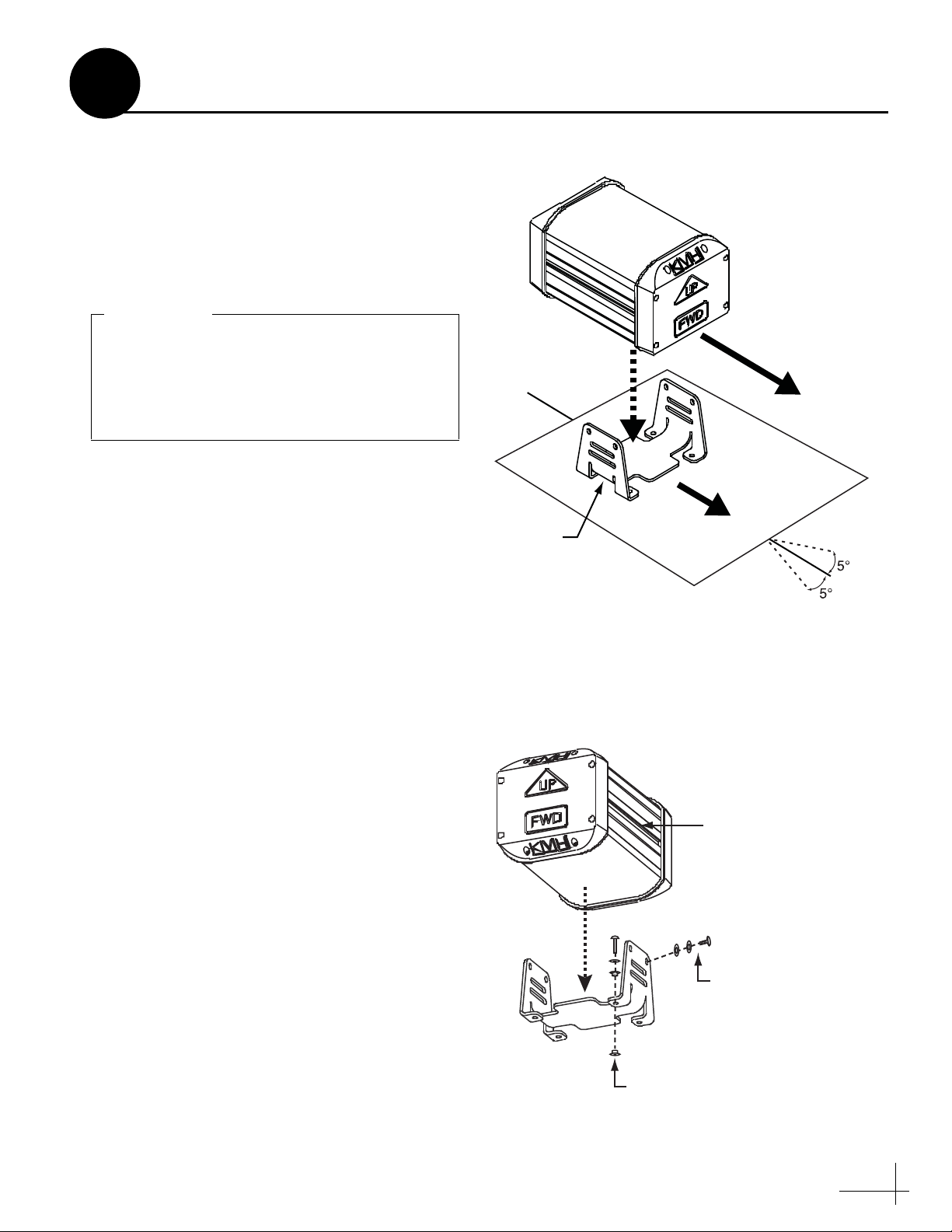
Figure 18: Sensor Alignment
#8 screw, flat washer,
and 2 fiber washers (x4)
#10-32 flat washer,
lock washer,
and screw (x4)
T-nuts within
housing track (x4)
Figure 19: Sensor Mounting to a Horizontal Surface
9
In Step 3, you identified a suitable GyroTrac
sensor mounting location. Now follow these
steps to mount the GyroTrac using one of the
following options:
Option 1 - Mount to a horizontal surface
Option 2 - Mount to a vertical surface
Mount the Sensor
Option 1 - Mount to a Horizontal Surface
a. Position the sensor on the mounting surface
so that its forward (“FWD”) reference points
toward the bow and is parallel to the vessel’s
centerline within ±5º (see Figure 18).
Horizontal
Bracket
TOWARD BOW
b. Place the horizontal bracket on the mounting
surface and align it in the same manner as the
sensor.
c. Using the holes in the bracket’s mounting feet
as a template, drill four 1/8" (3.5 mm) holes
in the mounting surface. Later, you will
attach the bracket to the mounting surface at
these four holes.
d. At each of the four mounting feet, insert a #8
fiber washer from above, and insert a #8 fiber
washer from below (see Figure 19). The fiber
washers will isolate the sensor from ground.
e. Secure the horizontal bracket to the mounting
surface using four #8 screws and flat washers.
f. Place the sensor onto the bracket. Make sure
the sensor‘s forward (“FWD”) reference
points toward the bow and its “Up” arrow
points upward.
g. Secure the sensor to the horizontal bracket
using four #10-32 screws, lock washers, and
flat washers. Insert the screws into the four
T-nuts held within the sensor’s housing track.
11
Page 12
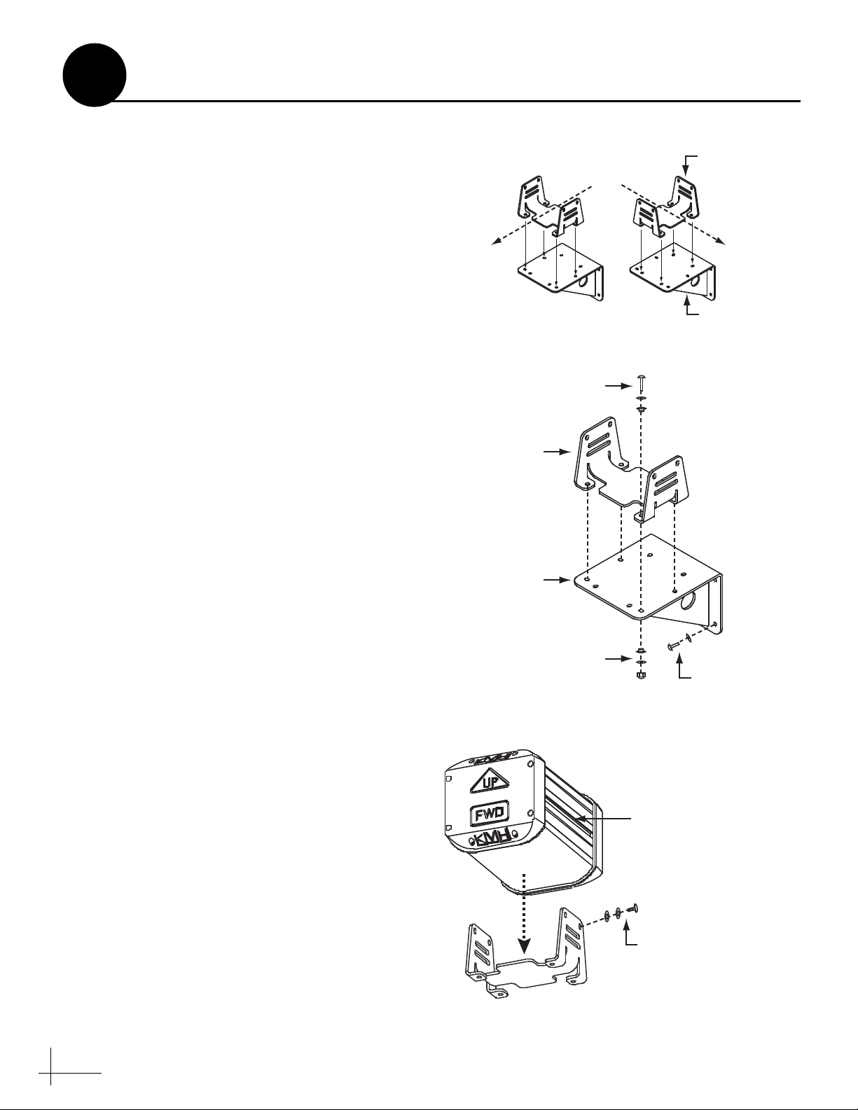
Figure 20: Bracket Orientation Options
#8 screw, flat washer,
and fiber washer (x4)
#8 fiber washer, flat washer,
and self-locking nut (x4)
Horizontal
Bracket
Vertical
Bracket
#8 screw and
flat washer (x4)
Figure 21: Bracket Mounting
#10-32 flat washer,
lock washer, and screw (x4)
T-nuts within
housing track (x4)
Figure 22: Sensor Mounting to a Vertical Surface
9
Continued Mount the Sensor
Option 2 - Mount to a Vertical Surface
a. The vertical bracket allows you to mount the
sensor (within its horizontal bracket) either
perpendicular or parallel to the mounting
surface (see Figure 20). Be sure to orient the
vertical and horizontal brackets so that the
sensor’s forward (“FWD”) reference will
point toward the bow and will be parallel to
the vessel’s centerline within ±5º (see
Figure 18 on page 11). Also make sure the
sensor will be level with the deck.
b. Using the holes in the vertical bracket’s
mounting feet as a template, drill four 1/8"
(3.5 mm) holes in the mounting surface.
c. Secure the vertical bracket to the mounting
surface using four #8 screws and flat washers
(see Figure 21).
d. Secure the horizontal bracket to the vertical
bracket using four #8 screws, eight flat
washers, eight fiber washers, and four selflocking nuts (see Figure 21). The fiber washers
will isolate the sensor from ground.
Vessel
Centerline
Horizontal
Bracket
OR
Vessel
Centerline
Vertical
Bracket
e. Place the sensor onto the horizontal bracket
(see Figure 22). Make sure the sensor‘s
forward (“FWD”) reference points toward
the bow and its “Up” arrow points upward.
f. Secure the sensor to the horizontal bracket
using four #10-32 screws, lock washers, and
flat washers. Insert the screws into the four
T-nuts held within the sensor’s housing track.
12
Page 13
If you wish to connect three or more receivers
to the antenna, see Appendix A on page 31
(circular) or page 32 (Sky Mexico).
IMPORTANT!
Antenna
SATELLITE IN
OUT TO TV
TV ANT/CABLE IN
AUDIO VIDEO S-VIDEO PHONE JACK
RL
Secondary Receiver - Optional
Primary Receiver
SATELLITE IN
OUT TO TV
TV ANT/CABLE IN
AUDIO VIDEO S-VIDEO PHONE JACK
RL
This receiver controls satellite selection
RF1RF2
(Optional)
RF1RF2
(Optional)
Grounding
Block
Satellite In
Satellite In
Vessel
AC Ground
Ground Wire
#6 Mounting
Screw (x2)
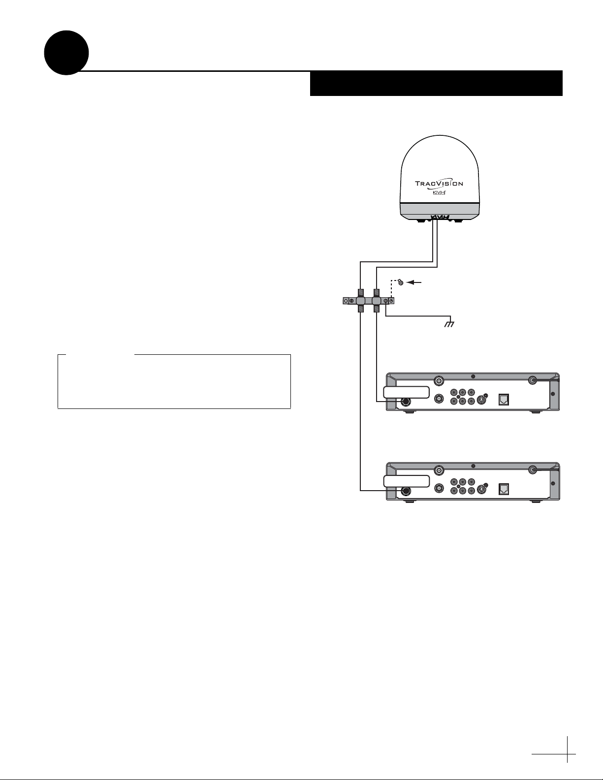
Figure 23: Wiring the Receivers to the Antenna
10
Wire the Receiver(s)
If you are installing a circular system, or a linear
system for Sky Mexico, follow these steps to
connect the customer’s satellite TV receiver(s) to
the TracVision system.
a. Connect the RF1 cable from the antenna to
the grounding block, as shown in Figure 23.
Label this grounding block connector “RF1.”
b. If you are connecting multiple receivers,
connect the RF2 cable from the antenna to the
grounding block. Label this connector “RF2.”
c. Attach the supplied ground wire to either
ground screw on the grounding block.
Connect the other end of the wire to a
suitable vessel AC ground.
d. Using the two #6 screws supplied with the
grounding block, mount the grounding block
inside the vessel.
Circular and Sky Mexico
e. If you are connecting two receivers to the
TracVision system, decide which receiver
will be the primary receiver. The primary
receiver controls satellite selection.
NOTE: The secondary receiver will be able to select
channels carried on the satellite that is currently
selected by the primary receiver.
f. Connect the supplied 5-ft RF cable from the
“RF1” connector on the grounding block to
the “Satellite In” connector on the primary
receiver (see Figure 23).
g. If you are connecting two receivers, connect
an RF cable from the “RF2” connector on the
grounding block to the “Satellite In”
connector on the secondary receiver.
h. Connect the receiver(s) to the customer’s
television(s). Follow the instructions in the
receiver’s manual.
13
Page 14
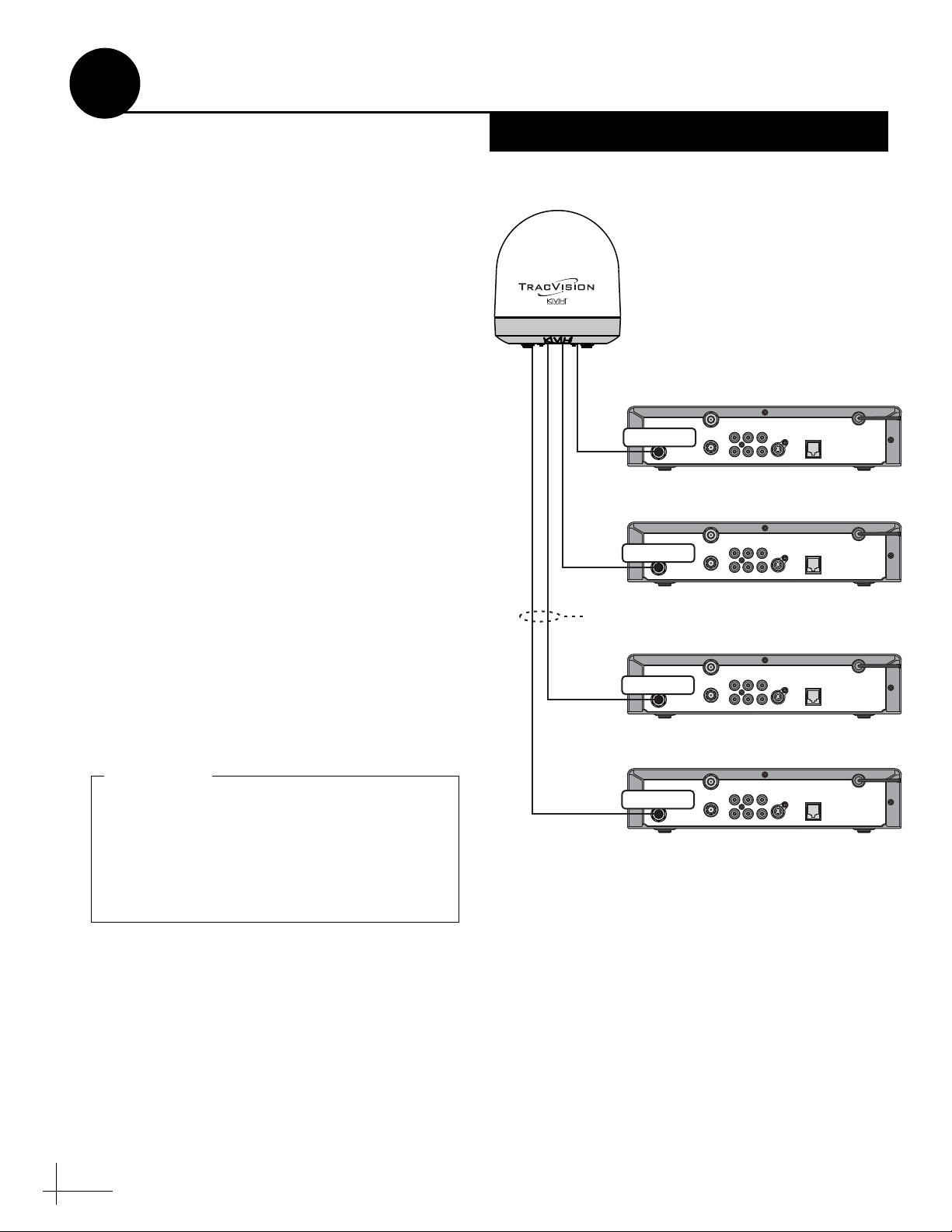
Figure 24: Wiring the Receivers to the Antenna
SATELLITE IN
OUT TO TV
TV ANT/CABLE IN
AUDIO VIDEO S-VIDEO PHONE JACK
RL
SATELLITE IN
OUT TO TV
TV ANT/CABLE IN
AUDIO VIDEO S-VIDEO PHONE JACK
RL
SATELLITE IN
OUT TO TV
TV ANT/CABLE IN
AUDIO VIDEO S-VIDEO PHONE JACK
RL
SATELLITE IN
OUT TO TV
TV ANT/CABLE IN
AUDIO VIDEO S-VIDEO PHONE JACK
RL
RF2
RF1
Antenna
Receiver #2
Receiver #1 (Primary)
Receiver #3
Receiver #4
RF3
RF4
This receiver controls satellite selection
Satellite In
Satellite In
Satellite In
Satellite In
(Optional)
(Optional)
(Optional)
Quad LNB Only
Be sure all receivers are grounded. If the
receiver has a 2-prong power plug, run a
ground wire from the receiver’s chassis to a
suitable ground point. If a potential exists
between AC and DC grounds, connect the
wire to the switchplate’s DC return instead.
IMPORTANT!
10
Wire the Receiver(s)
If you are installing a linear system (with the
exception of Sky Mexico), follow these steps to
connect the customer’s satellite TV receiver(s) to
the TracVision system.
a. If you are connecting multiple receivers to the
TracVision system, decide which receiver
will be the primary receiver. The primary
receiver controls satellite selection.
NOTE: The additional receiver(s) will be able to select
channels carried on the satellite that is currently
selected by the primary receiver.
b. Connect the RF1 cable from the antenna to
the “Satellite In” connector on the primary
receiver (see Figure 24).
c. If you have a second receiver, connect the
RF2 cable from the antenna to the “Satellite
In” connector on the second receiver.
d. If the system is equipped with a quad LNB
and you have a third receiver, connect the
RF3 cable from the antenna to the “Satellite
In” connector on the third receiver.
Linear Systems
e. If the system is equipped with a quad LNB
and you are connecting a fourth receiver,
connect the RF4 cable from the antenna to the
“Satellite In” connector on the fourth
receiver.
NOTE: If you need to connect more than four
receivers to the TracVision system, install an active
multiswitch that generates a 22 KHz tone (such as
Spaun model SMS 5602 NF - KVH part #19-0413).
Connect the multiswitch in accordance with the
manufacturer’s instructions.
f. Connect the receiver(s) to the customer’s
14
television(s). Follow the instructions in the
receiver’s manual.
Page 15
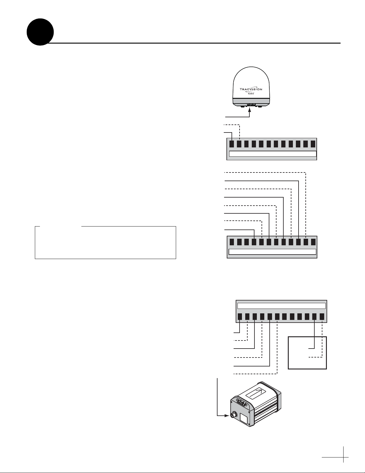
Figure 25: Wiring the Antenna to the ADCU
The diagrams refer to wires by body color/
stripe color. For example, “Blue/White”
means the blue wire with white stripe.
IMPORTANT!
Figure 26: Wiring the Sensor and GPS to the ADCU
11
Wire the ADCU
Follow these steps to connect the antenna data
and GyroTrac sensor cables to the ADCU.
NOTE: System wiring diagrams are provided in
Appendix H on page 46.
a. First dress the antenna data and power cables
from the antenna. Strip back the insulation of
each wire approximately 1/4" (6 mm) and
gently twist each wire to ensure a good
electrical connection.
b. Find the five terminal strip connectors in the
kitpack. You will connect wires to these
plastic connectors first. Later, you will plug
them into the rear panel of the ADCU.
c. Connect the data cable from the antenna to
the red and yellow ADCU terminal strip
connectors, as shown in Figure 25. Be sure to
snip and insulate any unused wires from the
cable, including the drain wire (shield).
Data
Green/White
White/Green
Data
Blue/White
White/Blue
Brown/White
White/Brown
Orange/White
White/Orange
Gray/White
White/Gray
Antenna
48 47 383940414243 37444546
Red Label
d. Connect the sensor cable to the GyroTrac
sensor. Hand-tighten until the cable locks in
place. Route the other end of the cable to the
ADCU.
e. Connect the sensor cable to the blue ADCU
terminal strip connector, as shown in
Figure 26.
f. (Optional) If you wish to connect the vessel’s
GPS to the TracVision system, connect the
GPS to the blue ADCU terminal strip
connector, as shown in Figure 26. A GPS
input will speed up satellite acquisition.
NOTE: For details on connecting other onboard
equipment, such as an autopilot, plotter, radar, or
remote display, see Appendix D on page 35.
GyroTrac Sensor
White/Green
White/Blue
Blue/White
White/Orange
Orange/White
Green/White
60 59 505152535455 49565758
Yellow Label
Blue Label
13 14 232221201918 24171615
GPS
GPS B-
GPS A+
(Optional)
Sensor
15
Page 16

Power Cable
Black
Red
Antenna
12-16 VDC
Ground
Vessel Power
Figure 27: Wiring Vessel Power to the Antenna
Power supplied to the antenna must not fall
below 12 VDC or exceed 16 VDC.
IMPORTANT!
12 1110987612543
Power In (Red)
Ground In (Black)
Vessel Power
(12-16 VDC)
Green Label
Figure 28: Wiring Vessel Power to the ADCU
Figure 29: Plugging In the ADCU Terminal Strip Connectors
Figure 30: Effective Strain-Relief of ADCU Wires
Double-check all of your wiring before
continuing. If wiring is incomplete or
incorrect, electronics may become damaged
when you apply power.
IMPORTANT!
12
Connect Power
Follow these steps to connect power to the
antenna and ADCU.
a. Before you begin, disconnect vessel power.
CAUTION
For your own safety, disconnect vessel power
and make sure the circuit is dead before you
connect any power wires.
b. Connect the power cable from the antenna to
12 VDC (4 amps continuous) vessel power
via a dedicated 10-amp circuit breaker (see
Figure 27).
c. Connect an additional power cable from
12 VDC vessel power to the power (+) and
ground (-) terminals on the green ADCU
terminal strip connector, as shown in
Figure 28 (for cable specifications, see
Figure 2 on page 3).
d. Plug all of the terminal strip connectors into
the rear panel of the ADCU. Be sure to plug
them into their correct positions, as shown in
Figure 29.
e. Using the supplied tie-wraps, strain-relieve
all wires at the ADCU. If a ferrite is installed
on the cable, position the ferrite as close as
possible to the terminal strip connections and
strain-relieve the wires next to the ferrite (see
Figure 30). Also be sure to allow just enough
slack in the cables for easy serviceability.
Yellow Label
9
4
50
51
253
5
4555
5
657
58
59
60
121
110
987
6
543
2
1
Green Label
Terminal Strip Connector
Red Label
24344
4546
47
48
18
17
16
5
1
14
13
Blue Label
37
38
39
40
414
6
3
3534
333
2
313
0
29
2827
26
25
242322
1
2
2019
White Label
16
Good
Strain-Relief
Tie-wrap
Ferrite
Tie-wrap
Ideal
Strain-Relief
Page 17

Fabric Strip (x4)
Hook Disk (x4)
#4-24 Screw (x4)
Figure 31: Velcro Mounting
Figure 32: Flush Mount Bracket
#8 Screws and
Washers (x4)
Figure 33: Flush Mounting the ADCU to a Vertical Surface
13
In Step 4, you identified a suitable ADCU
mounting location. Now follow these steps to
mount the ADCU using one of the following
options:
Option 1 - Velcro mount to a horizontal surface
Option 2 - Flush mount to a vertical surface
Mount the ADCU
Option 1 - Velcro Mount
a. Clean and dry the bottom of the ADCU and
the mounting surface (use a mild detergent).
b. Peel the backing from the four supplied
Velcro fabric squares and stick them to the
bottom corners of the ADCU (see Figure 31).
c. Position the four Velcro hook disks onto the
mounting surface. Drill screw holes for the
disks and secure in place with #4-24 screws.
d. Press the ADCU firmly into place so the
fabric’s loop material engages the hook disks.
Option 2 - Flush Mount
a. At the bottom of the ADCU, loosen the two
#6-32 screws (see Figure 32).
b. Slide the flush mount bracket backward onto
the ADCU until the two notches in the
bracket engage the screws at the bottom of
the ADCU.
c. Tighten the screws to secure the bracket to
the ADCU.
d. In Step 4 on page 6, you cut out the mounting
hole in the mounting surface. Insert the
ADCU and bracket assembly into this
mounting hole and secure in place with four
#8 screws and washers (see Figure 33).
#6-32 Screw (x2)
17
Page 18

Figure 34: Satellite Install Commands for Circular Tri-Sat Modes
* Optional Master Receiver Selector (KVH part #72-0412)
required for automatic satellite switching; multiswitch
(KVH part #72-0310) required for manual switching; see
Appendix A on page 31.
Tri-Sat Mode
(Satellites)
Command
DISH 1000/129
(119, 110, 129)*
SATINSTALL,TRISAT,
DISH
DISH 1000/61
(119, 110, 61)
SATINSTALL,TRISAT,
DISH61
Figure 35: Recommended Areas for DISH 1000 Satellites
= DISH 61 Satellite Recommended
= DISH 129 Satellite Recommended
If you wish to receive DISH Network’s threesatellite service, use the map in Figure 35 to
help determine the appropriate DISH 1000
mode for your area. Check with DISH Network
for local channels availability. If you want DISH
1000/61 service, skip this step and proceed to
page 21. If you want DISH 1000/129 service,
follow the procedure below.
IMPORTANT!
Programming DISH Network’s 119, 110, and
129 satellites:
HALT
DEBUGON
SATINSTALL,TRISAT,DISH
ZAP
EXAMPLE
14
Select Satellites
Follow these steps to set up a circular system for
one of the two available Tri-Sat modes for DISH
Network (see Figure 34). If you wish to set up the
system for one or two satellites instead, skip this
step and proceed to page 20.
a. Connect a laptop PC to the Maintenance port
on the back of the ADCU. See Appendix B on
page 33 for connection details.
b. Ensure the antenna has a clear, unobstructed
view of the sky.
Tri-Sat Mode - Circular
c. Apply power to the receiver(s), TV(s), ADCU,
and antenna. Wait one minute for system
startup.
d. Using Windows HyperTerminal (or
equivalent) or KVH Flash Update Wizard,
type HALT then press Enter.
e. Type DEBUGON then press Enter.
f. Type the appropriate command in Figure 34
for the desired Tri-Sat mode.
g. Type ZAP then press Enter. The antenna
restarts. Wait one minute for system startup.
18
Page 19

Figure 36: Satellite Install Commands for Linear Tri-Sat Modes
Satellites Command
A = Hotbird
B = Astra 1
C = Astra 2S
SATINSTALL,TRISAT,
EUR
A = Hotbird WB
B = Astra 1
C = Astra 2S
SATINSTALL,TRISAT,
EWB
A = Hotbird WB
B = Sirius
C = Thor
SATINSTALL,TRISAT,
SCN
Programming the Hotbird WB, Astra 1, and
Astra 2S satellites:
HALT
DEBUGON
SATINSTALL,TRISAT,EWB
ZAP
EXAMPLE
14
Select Satellites
Follow these steps to set up a linear system for
one of the three available Tri-Sat modes (see
Figure 36).
one or two satellites instead, skip this step and
proceed to page 20.
a. Connect a laptop PC to the Maintenance port
on the back of the ADCU. See Appendix B on
page 33 for connection details.
b. Ensure the antenna has a clear, unobstructed
view of the sky.
c. Apply power to the receiver(s), TV(s), ADCU,
and antenna. Wait one minute for system
startup.
d. Using Windows HyperTerminal (or
equivalent) or KVH Flash Update Wizard,
type HALT then press Enter.
e. Type DEBUGON then press Enter.
f. Type the appropriate command in Figure 36
for the desired Tri-Sat mode.
If you wish to set up the system for
Tri-Sat Mode - Linear
g. Type ZAP then press Enter. The antenna
restarts. Wait one minute for system startup.
h. If you have not installed a multiswitch, set up
the receiver(s) for the same satellites, and in
the same order, that you set them up in the
antenna:
Antenna Receiver DiSEqC
Sat. A Alternative 1 or A DiSEqC 1
Sat. B Alternative 2 or B DiSEqC 2
Sat. C Alternative 3 or C DiSEqC 3
This synchronization is necessary to enable
automatic satellite switching.
19
Page 20

Figure 37: Satellite Selection Menus on ADCU
14
Select Satellites
Follow these steps to set up the system for one or
two satellites.
a. Ensure the antenna has a clear, unobstructed
view of the sky. Then apply power to the
receiver(s), TV(s), ADCU, and antenna. Wait
one minute for system startup.
b. Press the center MENU button on the ADCU
to access the onscreen menu (see Figure 37).
c. At “Setup display type?”, press NEXT until
the display shows “Control antenna?” Then
press ENTER and press YES to confirm.
d. At “Man control antenna?”, press NEXT until
the display shows “Install satellite?” Then
press YES.
e. At “Install A <SAT NAME>”, press NEXT
until the display shows the first (primary)
satellite you want to select. Then press YES.
(See Appendix C on page 34 for a list of
available satellites.)
NOTE: If you don’t find the satellite you want, you
can set up user-defined satellites. Refer to the
associated Application Note on the KVH Partner
Portal (KVH-authorized technicians only).
Dual-Sat or Single-Sat Mode
Menu
Setup display type?
Enter Next Return
Until “Control antenna” shown
Control antenna?
Enter Next Return
At “ARE YOU SURE?,” press YES
Man control antenna?
Yes Next Return
Until “Install satellite” shown
Install satellite?
Yes Next Return
Install A <SAT NAME>
Yes Next Cancel
f. Repeat Step e to select the second satellite. If
you want to set up the antenna to track just
one satellite, select “None” instead.
g. (If necessary) At “Latitude”, use the - and +
buttons to set each digit of the vessel’s
latitude. Press ENTER to accept each digit.
(See Appendix G on page 45 for approximate
positions in Europe or North America.)
h. At “Longitude”, set the vessel’s longitude.
i. At “Restart antenna?”, press YES. Wait one
minute while the antenna restarts.
j. (Linear systems only) If you have not
installed a multiswitch, set up the receiver(s)
for the same satellites, and in the same order,
that you set them up in the antenna:
Antenna Receiver DiSEqC
Sat. A Alternative 1 or A DiSEqC 1
20
Sat. B Alternative 2 or B DiSEqC 2
Press NEXT until desired satellite shown
Install B <SAT NAME>
Yes Next Cancel
Press NEXT until desired satellite shown
Installing sats
Please wait
<SAT NAME1> and
<SAT NAME2> installed
Latitude: ##N
- Enter +
Use +/- to set vessel latitude
Longitude: ###E
- Enter +
Use +/- to set vessel longitude
Latitude: ##N
Longitude: ###E
Restart antenna?
Yes No
Not shown if a GPS
is connected and is
providing valid data
Page 21

If you set up the system for one or two
satellites, you may skip this step since you
already entered latitude/longitude during
the satellite selection process; proceed to
page 22.
IMPORTANT!
Figure 38: Lat/Long Menus on ADCU
15
Enter Your Latitude & Longitude
This step does not apply to linear systems with
Auto Skew capability.
If you set up the system for a Tri-Sat mode, and
you do not have a GPS connected to the ADCU,
follow these steps to enter your vessel’s latitude
and longitude into the system.
NOTE: The antenna will use your position
information to speed up satellite acquisition. If the
antenna knows where you are, it knows where it
should start looking for the satellite. In addition, for a
linear system, the antenna will use your position
information to calculate the correct LNB skew angle.
TIP: You can determine your approximate latitude
and longitude in Europe or North America from the
position grids provided in Appendix G on page 45.
a. Press the center MENU button on the ADCU
to access the onscreen menu (see Figure 38).
b. At “Setup display type?”, press NEXT until
the display shows “Control antenna?” Then
press ENTER and press YES to confirm.
c. At “Man control antenna?”, press NEXT until
the display shows “Set Lat/Long?” Then
press YES.
d. At “Latitude”, use the - and + buttons to set
each digit of the vessel’s latitude. Press
ENTER to accept each digit.
e. At “Longitude”, set the vessel’s longitude.
Tri-Sat Mode Only
Menu
Setup display type?
Enter Next Return
Until “Control antenna” shown
Control antenna?
Enter Next Return
At “ARE YOU SURE?,” press YES
Man control antenna?
Yes Next Return
Until “Set Lat/Long” shown
Set Lat/Long?
Yes Next Return
Latitude: ##N
- Enter +
Use +/- to set vessel latitude
Longitude: ###E
- Enter +
Use +/- to set vessel longitude
Latitude: ##N
Longitude: ###E
Set Lat/Long?
Yes Next Return
Until “Restart antenna” shown
Restart antenna?
Yes Next Return
f. At “Set Lat/Long?,” press NEXT until the
display shows “Restart antenna?” Then press
YES. Wait one minute while the antenna
restarts.
21
Page 22

Figure 39: Skew Angle Menus on ADCU
16
Get the LNB Skew Angle
This step does not apply to linear systems with
Auto Skew capability.
To optimize reception, the antenna’s LNB must
be set to the correct skew angle for the linear
satellite(s) you want to track. Follow these steps
to determine the correct skew angle for your
currently selected satellite and vessel position.
TIP: You might also be able to get the correct skew
angle from the customer’s satellite service provider.
a. Press the center MENU button on the ADCU
to access the onscreen menu (see Figure 39).
b. At “Setup display type?”, press NEXT until
the display shows “Get antenna status?”
Then press ENTER and press YES to confirm.
c. At “Get system errors?”, press NEXT until
the display shows “Get skew angle?” Then
press YES.
Linear Systems Only
Menu
Setup display type?
Enter Next Return
Until “Get antenna status” shown
Get antenna status?
Enter Next Return
At “ARE YOU SURE?,” press YES
Get system errors?
Yes Next Return
Until “Get skew angle” shown
d. The display shows the calculated skew angle
for the selected satellite and position. Note
this number for future reference.
NOTE: If you did not connect a GPS to the ADCU,
the antenna will use the position information you
entered earlier to calculate the correct LNB skew
angle.
e. Press any button. The display returns to the
“Get skew angle?” screen.
f. Press RETURN until you exit the menu.
TIP: This procedure provides the correct skew angle
for the currently selected satellite only. If you selected
multiple satellites in Step 14, you might wish to
calculate the average skew instead. To find the
average skew, select the second satellite (see the User’s
Guide for details) then repeat the procedure above to
get the calculated skew angle for the second satellite
(repeat for the third satellite if Tri-Sat). Add the skew
angle numbers and divide by two (or three if Tri-Sat)
to get the average.
Get skew angle?
Yes Next Return
Skew angle
##.#
Press any button to exit
22
Page 23

M4 Socket
Set Screws
Reflector
LNB
Figure 40: Set Screws Securing the LNB to the Reflector
Figure 41: LNB Skew Angle Adjustment
Be sure to keep the LNB fully inserted into the
choke feed to ensure optimum performance.
IMPORTANT!
17
Set the LNB Skew Angle
This step does not apply to linear systems with
Auto Skew capability.
Follow these steps to set the antenna’s linear LNB
to the skew angle you noted in Step 16.
a. Turn off and unplug the receiver(s) and
disconnect antenna power.
CAUTION
Disconnect power from the antenna and the
receivers before you adjust the LNB. The
antenna’s moving parts can cause injury.
b. Remove the antenna’s radome, if you
reinstalled it earlier in Step 8.
c. Locate the LNB on the back of the antenna’s
reflector (see Figure 40).
d. Using a 2 mm allen hex key, loosen the two
M4 socket set screws on the LNB choke feed.
These screws secure the LNB in place.
Linear Systems Only
e. Adjust the LNB clockwise or counter-
clockwise until the skew arrow on the LNB
points to the skew angle that you noted in
Step 16 (see Figure 41).
f. Tighten the two M4 socket set screws to
secure the LNB in place. Apply 9 in-lbs
(1 Nm) of torque, if possible.
g. Reinstall the radome (as explained in
Steps 8e-f on page 10).
90
85
80
70
75
60
65
55
Negative
Skews
LNB
Choke Feed
S
K
W
E
90
85
80
75
70
50
40
45
30
35
25
20
10
15
5
0˚ Skew
0
20
10
15
5
60
65
0
5
5
5
40
0
3
45
35
25
Positive
Skews
23
Page 24

If you purchased a preconfigured DISH
receiver from KVH, you only need to run one
Check Switch test to set up the system.
IMPORTANT!
Figure 42: Expected Check Switch Results Displayed on TV
DISH 1000/129 Results
DISH 1000/61 Results
DISH 500 Results
Bell TV Results*
* If you installed just one Bell TV satellite, the TV will show
Port 123
Satellite 119 110 129
Trans OKOKOK
Status Reception Verified
Switch SW64
Port 123
Satellite 119 110 61
Trans OKOKOK
Status Reception Verified
Switch SW64
Input 1122
Satellite 119 119 110 110
Polarity Odd Even Odd Even
Status Reception Verified
Switch SW42
Input 1122
Satellite91918282
Polarity Odd Even Odd Even
Status Reception Verified
Switch SW21
18
Run Check Switch Tests
If you set up the system for DISH Network or
Bell TV (formerly ExpressVu), follow these steps
to run the receiver’s Check Switch test as
required.
Primary Receiver - 2 Check Switch Tests
Follow these steps to run two Check Switch tests
on the primary receiver, which is connected to
the antenna’s “RF1” cable. This receiver will
control satellite selection.
a. Make sure the vessel is docked in calm water
in a blockage-free area. Ensure the antenna
has an unobstructed view of the sky.
b. Apply power to the TV and receiver. (If the
antenna is turned off, turn it back on and wait
a few minutes for startup.)
c. Using the receiver’s remote, go to the “Point
Dish/Signal Strength” screen (press MENU,
6, 1, 1 on most models).
DISH Network or Bell TV Only
d. Choose Check Switch, then press SELECT.
e. Choose Check or Test, then press SELECT.
f. Wait at least 15 minutes before proceeding to
allow the antenna to find all of the satellites.
Disregard any messages on the TV; they do
not correctly indicate when the antenna is
ready for the next Check Switch test.
g. Once you have waited the proper amount of
time, choose Retest or Test, then press
SELECT to run a second Check Switch test.
h. Refer to the tables in Figure 42 and verify the
values displayed on your TV match those
required for your selected service.
If your values match, exit the menu. The
receiver will download the program guide.
If your values do not match, turn off the
antenna, then turn it back on and repeat
Steps c-h.
24
Page 25

18
Continued Run Check Switch Tests
Additional Receiver(s) - 1 Check Switch
Test
If you connected multiple receivers, follow these
steps to run a Check Switch test on each
additional receiver (one at a time), unless it is a
preconfigured DISH receiver. When you are done,
reconnect the receivers as before.
a. Temporarily disconnect the primary receiver
from the antenna’s “RF1” cable.
b. Connect the additional receiver to t he
antenna’s “RF1” cable.
c. Perform Steps a-e on page 24 to run a single
Check Switch test on the receiver.
d. Wait 15 minutes, then verify the values on the
TV match the values shown in Figure 42 on
page 24. If your values do not match, try
running another Check Switch test.
25
Page 26

Figure 43: Running Autocalibration
Figure 44: Viewing the Calibration Score on the ADCU
19
Calibrate the Sensor
Every GyroTrac sensor is calibrated at the factory
for a perfect-world environment. However, hard
and soft iron effects on your vessel can distort the
magnetic field around the sensor, causing errors
in its reported heading. To compensate for these
magnetic distortions, follow these steps to
calibrate the sensor.
2 Minutes
NOTE: If you are not installing the GyroTrac sensor
for the first time, you will need to clear the calibration
score first (see Appendix F on page 44).
Run the Autocalibration Function
The system’s Autocalibration function is set to
“On” at the factory. This function allows the
sensor to calibrate itself automatically when you
steer the vessel through two circles.
a. Select a calm day and navigate the vessel to a
clear area. Excessive pitching and rolling can
distort calibration data.
b. Apply power to the TracVision system.
c. Just before you begin, note the vessel’s
heading.
d. Steer the vessel at a slow, steady speed
through two full circles that take at least two
minutes each to complete (see Figure 43). Use
the heading you noted in Step c to confirm
when you have completed each full circle.
1 Minute,
30 Seconds
Menu
1 Minute
C
i
r
c
l
C
e
i
#
r
c
1
l
e
#
2
30 Seconds
TIP: Try to time your turns so that it takes
approximately 30 seconds to turn 90º. Each circle does
not have to be completely round, but make sure you
turn a full 360º for each.
Check the Calibration Score
Once you have completed the two circles, follow
these steps to check the calibration “score.”
a. Press the center MENU button on the ADCU
to access the onscreen menu (see Figure 44).
b. At “Setup display type?”, press NEXT until
the display shows “Control compass?” Then
press ENTER and press YES to confirm.
26
Setup display type?
Enter Next Return
Until “Control compass” shown
Control compass?
Enter Next Return
At “ARE YOU SURE?,” press YES
Set AutoCal On/Off?
Yes Next Return
Until “Read cal score” shown
Read Cal score?
Yes Next Return
Page 27

Acc MagEnv Cal#
Cal<1° GOOD 1
Accuracy
Rating
Calibration
Number
Magnetic
Environment
Figure 45: Calibration Score Example
Data Field Description
Accuracy
Rating
Degree of accuracy the
sensor will provide
(Cal<1º = within 1º)
Magnetic
Environment
Quality of the sensor’s
installation site
Calibration
Number
Number of times the
sensor was calibrated
Figure 46: Turning Off Autocalibration at the ADCU
19
c. At “Set AutoCal On/Off?”, press NEXT until
the display shows “Read Cal score?” Then
press YES.
d. The display shows the calibration score for
the calibration you just performed with the
Autocalibration function (see Figure 45).
e. If Accuracy = “BAD CAL”:
Recalibrate the sensor by navigating through
two additional circles. Repeat until you
achieve a suitable accuracy rating.
f. If Mag. Environment = “POOR” or “BAD”:
Relocate the sensor to a more favorable
magnetic environment (see Step 3 on page 5
for guidelines). Then clear the calibration
score (see Appendix F on page 44) and
recalibrate the sensor.
g. Press the center button. The display returns
to the “Read Cal score?” screen.
Continued Calibrate the Sensor
h. Press RETURN until you exit the menu.
Turn Off Autocalibration
Once you have achieved a good calibration score,
follow these steps to turn off the Autocalibration
function.
a. Press the center MENU button on the ADCU
to access the onscreen menu (see Figure 46).
b. At “Setup display type?”, press NEXT until
the display shows “Control compass?” Then
press ENTER and press YES to confirm.
c. At “Set AutoCal On/Off?”, press YES.
d. At “AutoCal is: ON”, press OFF.
e. At “AutoCal is: OFF”, press ENTER. The
display returns to the “Set AutoCal On/Off?”
screen.
f. Press RETURN until you exit the menu.
Menu
Setup display type?
Enter Next Return
Until “Control compass” shown
Control compass?
Enter Next Return
At “ARE YOU SURE?,” press YES
Set AutoCal On/Off?
Yes Next Return
AutoCal is: ON
On Enter Off
AutoCal is: OFF
On Enter Off
27
Page 28

Figure 47: North American Receiver Activation Information
Service: Call to Activate:
DIRECTV
1-866-551-8004
(24 hours, 7 days a week)
DISH Network
1-866-399-8509
(Mon.-Fri., 8:30am - 5pm ET)
Bell TV
1-888-759-3474 (SKY-DISH)
(24 hours, 7 days a week)
Figure 48: Example of Satellite Blockage
20
Before you leave the vessel, test the system to
verify the antenna works properly. Then give the
Customer Welcome Kit to the customer and be
sure the customer understands the following:
• The receiver(s) must be activated before it can
decode satellite TV signals. Refer to Figure 47
for activation details for North America.
• Keep the radome installed on the antenna at
all times. The radome protects the antenna’s
moving parts from wind, rain, and debris.
Educate the Customer
WARNING
It is dangerous to watch TV while piloting a
vessel. While under way, the system is
intended for passenger entertainment only.
• The antenna must have a clear view of the
sky to receive satellite TV. Common causes of
blockage include trees, buildings, bridges,
and onboard equipment (see Figure 48).
Heavy rain or snow may also temporarily
interrupt reception.
• Clean the antenna regularly. Dirt buildup on
the radome can affect reception.
• DISH 1000 modes only: You might need to
change the operating mode when traveling
between regions (see “Select Satellites” on
page 18).
• Linear only: If the system does not have Auto
Skew capability, you might need to adjust the
skew angle of your antenna’s LNB when you
travel to other geographic locations, (see “Get
the LNB Skew Angle” on page 22).
• The vessel must be located within the
selected satellite’s coverage area to receive its
satellite TV signals. To view satellite coverage
28
maps, visit www.kvh.com/footprint.
• Please register the system with KVH. The
registration process is quick, easy, online, and
ensures the best possible service from KVH.
Visit www.kvh.com/register or refer to the
Product Registration Form for details.
• Refer to the User’s Guide for operation and
troubleshooting information.
TracVision
Page 29

Appendices
This section provides supplemental instructions for wiring multiple receivers. It also provides a
list of available satellites, system wiring diagrams, and a mounting template for the belowdecks
equipment.
Contents
A. Wiring 3+ Receivers............................ 31
B. Connecting a PC to the ADCU .......... 33
C. Satellite Library.................................... 34
D. Connecting External Equipment....... 35
E. Entering Sensor Offset Values........... 42
F. Clearing the Calibration Score........... 44
G. Position Grids....................................... 45
H. Wiring Diagrams................................. 46
I. ADCU Flush Mounting Template..... 51
29
Page 30

Figure 49: Wiring Up to 4 Receivers
A
Wiring 3+ Receivers
If you need to connect three or more receivers, or
you set up the system for DISH Network’s 129
satellite (one or more receivers), install an active
(powered) multiswitch or Master Receiver
Selector between the grounding block and the
receivers, as shown in Figure 49.
NOTE: If you need to connect more than four
receivers, please contact KVH Technical Support.
Active Multiswitch
The optional Eagle Aspen multiswitch with AC/
DC power supply (KVH part #72-0310) allows
you to connect up to four receivers to the
TracVision system. However, since a multiswitch
interrupts satellite switching communications
between the receiver and the antenna, you will
need to manually switch between your selected
satellites using the buttons on the ADCU’s front
panel (see the User’s Guide for details).
AC Power In
100-240 V AC
50-60 Hz
DC Power
Supply
Circular Systems
Antenna
RF1 RF2
Grounding Block
Vessel
AC Ground
IMPORTANT!
Multiswitch connections
for DISH 1000/129:
RF1=13V; RF2=18V
13V/RF218V/RF1Power/DC
OR
Master Receiver SelectorActive Multiswitch
Master Receiver Selector
The optional KVH Master Receiver Selector
(KVH part #72-0412) is an enhanced multiswitch
that provides the following capabilities:
• Automatic satellite switching in any
operating mode, including DISH 1000/129.
• Support for multiple receivers.
• Capability for the user to select, at any time,
which receiver controls satellite selection.
Simply turn the knob!
Receiver 1 Receiver 2 Receiver 3 Receiver 4
Receiver #4
SATELLIT E IN
TV ANT/CABLE IN
OUT TO TV
RL
AUDIO VIDEO S-VIDEO PHONE JACK
Satellite In
Receiver #3
SATELLIT E IN
TV ANT/CABLE IN
OUT TO TV
RL
AUDIO VIDEO S-VIDEO PHONE JACK
Satellite In
Receiver #2
SATELLIT E IN
TV ANT/CABLE IN
OUT TO TV
RL
AUDIO VIDEO S-VIDEO PHONE JACK
Satellite In
Receiver #1
SATELLIT E IN
TV ANT/CABLE IN
OUT TO TV
RL
AUDIO VIDEO S-VIDEO PHONE JACK
Satellite In
31
Page 31

SATELLITE IN
OUT TO TV
TV ANT/CABLE IN
AUDIO VIDEO S-VIDEO PHONE JACK
RL
Satellite In
SATELLITE IN
OUT TO TV
TV ANT/CABLE IN
AUDIO VIDEO S-VIDEO PHONE JACK
RL
Satellite In
SATELLITE IN
OUT TO TV
TV ANT/CABLE IN
AUDIO VIDEO S-VIDEO PHONE JACK
RL
Satellite In
SATELLITE IN
OUT TO TV
TV ANT/CABLE IN
AUDIO VIDEO S-VIDEO PHONE JACK
RL
Receiver #3
Receiver #2
Receiver #1
Receiver #4
Satellite In
RF2 RF1
Grounding
Block
Vessel
AC Ground
Ground Wire
RF2 RF1
AC Power In
100-240 V AC
50-60 Hz
H/High
V/HighH/Low
V/Low
LNB
22 KHz
18V
12V
432
1
5
6
Receivers
Terr
Multiswitch
Figure 50: Multiswitch Wiring - Sky Mexico
A
Wiring 3+ Receivers
To connect three or more receivers to a system
configured for Sky Mexico, follow these steps to
install a Spaun model SMS 5602 NF multiswitch
(KVH part #19-0413) between the grounding
block and the receivers, as shown in Figure 50.
1. Connect an RF cable from the “RF1”
connector on the grounding block to the
“H/High” (Horizontal High) connector on
the multiswitch.
2. Connect an RF cable from the “RF2”
connector on the grounding block to the
“V/High” (Vertical High) connector on the
multiswitch.
3. Set the multiswitch’s LNB knob to “22 KHz.”
At this setting, the multiswitch will provide a
constant 22 KHz tone to the antenna’s LNB.
4. Connect the receivers to the individual
outputs of the multiswitch.
5. Connect the receivers to the customer’s TVs.
Sky Mexico Systems
32
Page 32

Figure 51: Technician Programming the Antenna
Figure 52: Maintenance Port on ADCU
ON
OFF
Maintenance Port
Maintenance Port
Figure 53: HyperTerminal Settings
Maintenance Port
B
If you need to manually enter commands into the
antenna (for example, to set up the system for a
Tri-Sat mode), follow these steps to connect your
laptop PC to the ADCU.
NOTE: If you are a KVH-authorized technician, you
can use the KVH Flash Update Wizard instead of
HyperTerminal. Enter commands in the wizard’s
“TracVision Antenna Comms” window.
1. Using a PC serial data cable, connect your
laptop to the DB9 Maintenance port on the
back of the ADCU (see Figure 52).
NOTE: If your computer does not have a DB9 serial
COM port, you can use the USB-to-RS232 adapter
manufactured by IOGear (IOGear part number
GUC232A) or Belkin (Belkin part number F5U257,
F5U109, or F5U409). Windows Vista users should
use one of the Belkin models; 64-bit Windows Vista/7
users should use Belkin #F5U257.
Connecting a PC to the ADCU
2. Open Windows HyperTerminal (or
equivalent) and establish the following
settings for your COM port (see Figure 53):
• Bits per second: 9600
• Data bits: 8
•Parity: None
• Stop bits: 1
•Flow control: None
TIP: To view characters on the screen as you type, set
up HyperTerminal to echo typed characters. Select
“Properties” from the File menu; select “ASCII
Setup” at the Settings tab; then select “Echo typed
characters locally” at the ASCII Setup window.
33
Page 33

C
The TracVision antenna can track a variety of
DVB-compatible and DSS (DIRECTV) satellites.
Most popular satellites are programmed in the
antenna’s library (see the tables below).
Satellite Library
North America
Circular LNB Required
DIRECTV Dual-Sat: DSS_101, DSS_119
DISH 500: ECHO_119, ECHO_110
Bell TV: EXPRESSTV, EXPRESSVU
Satellite, Longitude Name in Library
DIRECTV, 72°W DSS_72
DIRECTV, 101°W DSS_101
DIRECTV, 110°W* DSS_110
DIRECTV, 119°W DSS_119
EchoStar, 61°W ECHO_61
EchoStar, 110°W ECHO_110
EchoStar, 119°W ECHO_119
EchoStar/Ciel 2, 129°W ECHO_129
Europe
Linear LNB Required
Satellite, Longitude Name in Library
Astra 1, 19.2°E ASTRA1
Astra 2N, 28.2°E ASTRA2N
Astra 2S, 28.2°E ASTRA2S
Hispasat, 30.0°W HISPASAT
Hotbird, 13.0°E HOTBIRD
Hotbird WB, 13.0°E HOTBIRDWB
Astra (Sirius), 5.0°E SIRIUS
Thor, 0.8°W THOR
Arabsat/Badr 4, 26°E ARABSAT
Nilesat, 7°W NILESAT
Bell TV, 82°W EXPRESSVU
Bell TV, 91°W EXPRESSTV
* DIRECTV HD not supported.
Asia
Circular LNB Required
Satellite, Longitude Name in Library
Asiasat 4, 122.2°E ASIASAT
Sinosat 1, 110.5°E* SINOSAT
* Special LNB required. Call KVH at 1-401-847-3327.
Latin America
Galaxy Circular LNB Required
Satellite Name in Library
Turksat 1C, 42°E TURKSAT1C
Eutelsat W3A, 7°E EUTEL_W3A
Mexico (Sky Mexico Service)
Linear LNB Required
Satellite, Longitude Name in Library
PAS 9/Intelsat 9, 58°W PAS_9
Australia & New Zealand
Linear LNB Required
Satellite Name in Library
Optus D1, 160°E OPTUS_D1
Optus C1, 156°E OPTUS_C1
Galaxy 3C, 95°W GALAXY3CN
34
Page 34

Figure 54: Optional Rotating Card Display (Part #19-0120)
D
In addition to TracVision and GPS connections,
the ADCU rear panel includes three optional
compass outputs of the following formats:
• One sine/cosine output
• Two serial outputs (each configurable for
These compass outputs allow you to supply the
GyroTrac sensor’s heading data to other
electronic devices, such as autopilots, radars,
remote displays, plotters, and computers
onboard the vessel.
NOTE: KVH offers a rotating card display (KVH part
#19-0120) for presenting sensor heading information
(see Figure 54). This device, powered by 11-40 VDC,
connects to any one of the ADCU’s serial outputs,
configured for NMEA.
Connecting External Equipment
NMEA 0183, KVH RS-422, or Cetrek)
NOTE: If you wish to connect a ship’s gyro to the
system, connect the gyro to the ADCU’s GPS input
terminals (see Figure 26 on page 15).
Before you connect an external device, consider
the following guidelines:
• The device must comply with NMEA
Standard 2.2
• Data conductor wires should be
minimum 18 AWG (0.75 mm
pair, stranded, tinned marine cable
• Do not use cables with wire diameters
larger than 12 AWG (4 mm
the largest gauge the ADCU can accept
• Always follow the manufacturer’s wiring
guidelines in the device’s manual
This appendix explains how to wire and
configure each type of compass output from the
ADCU.
2
), twisted-
2
), since this is
35
Page 35

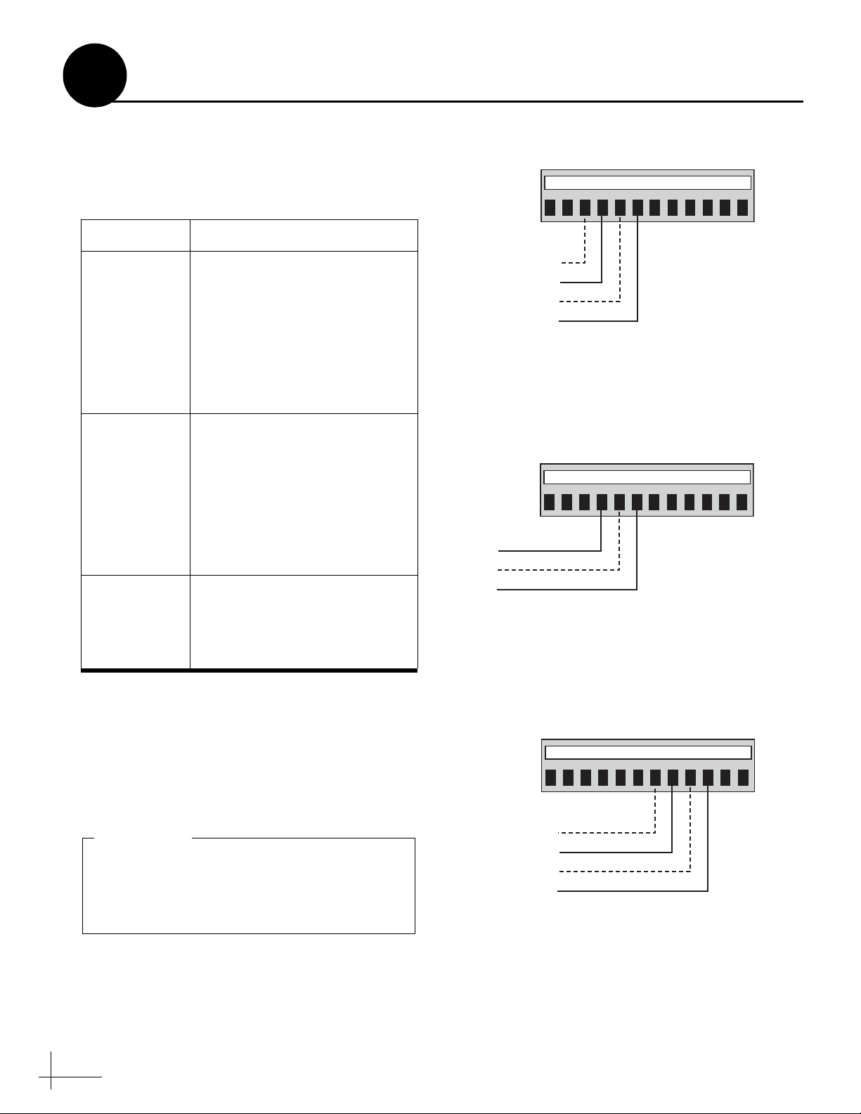
Figure 55: Sine/Cosine ADCU Wiring
D
Continued Connecting External Equipment
Sine/Cosine Output
The sine/cosine output can be configured for a
3-wire or 4-wire sine/cosine output, commonly
used with ComNav
autopilot systems.
Before you connect the external device, consider
the following important notes:
• The ADCU’s sine/cosine reference
voltage is an output, not an input. Do not
connect this terminal (#8) to the reference
output of the external device.
• If the device has its own internal
reference, do not connect the device to the
ADCU’s reference terminal (#8).
• Before you connect the device’s internal
ground wire to the ADCU, use a lowimpedance voltmeter to verify there is no
DC voltage present between the two
terminals. A DC surge could damage the
electronics.
®
, Robertson®, and other
Green Label
12 1110987612543
Ground
Ref. Voltage
Cosine (inverted)
Cosine
Sine (inverted)
Sine
• The maximum current draw from the
ADCU sine/cosine output is 10 mA.
• The B&G 4-wire sine/cosine output (also
known as “differential sine/cosine”) is a
substitute of the Halcyon
Sine/Cosine Output Wiring
In most cases, wire the device to the sine/cosine
output as noted below (see Figure 55).
External Device Wire: Connect to Green
Sine 12
Cosine 10
Internal power ground
(not chassis ground)
Reference (input) 8 (KVH output)
®
compass.
ADCU Terminal:
7
36
Page 36

Setup display type?
Enter Next Return
Menu
Until “Setup data outputs” shown
Use +/- to set reference voltage
Setup data outputs?
Enter Next Return
Set sine-cos levels?
Yes Next Return
Sine cosine is: Mag
Mag Enter True
Set Ref: 2.50 V
- Enter +
Set Swing: +/- 1.67V
- Enter +
Select Mag or True
Use +/- to set swing voltage
At “ARE YOU SURE?,” press Yes
Figure 56: Sine/Cosine Output Configuration Menus on ADCU
If you did not connect a GPS to the system,
only magnetic heading is available. If you
connected a ship’s gyro to the system, only
true heading is available.
IMPORTANT!
D
Sine/Cosine Output Configuration
Once you have finished the system installation,
configure the ADCU’s sine/cosine output for the
desired heading format and the correct voltages
for the external device.
1. Press the center MENU button on the ADCU
to access the onscreen menu (see Figure 56).
2. At “Setup display type?”, press NEXT until
the display shows “Setup data outputs?”
Then press ENTER and press YES to confirm.
3. At “Set sine-cos levels?”, press YES.
4. Now you need to select the desired heading
format. At “Sine cosine is”, press MAG to
select magnetic heading, or press TRUE to
select true heading. Then press ENTER.
Continued Connecting External Equipment
5. At “Set Ref”, use the - and + buttons to set the
reference voltage (0 - 6.5 volts). Then press
ENTER.
TIP: If you do not know the correct reference voltage
for the external device, connect a voltmeter between
the ADCU’s reference terminal (#8) and the reference
terminal on the external device. Then simply adjust
the reference voltage on the ADCU until the voltmeter
indicates zero volts (0 VDC).
NOTE: If you are using a B&G 4-wire sine/cosine
output as a substitute for a Halcyon compass, set the
reference voltage to 3.5 volts.
6. At “Set Swing”, use the - and + buttons to set
the swing voltage (±0 - 6.5 volts). Then press
ENTER.
37
Page 37
12 1110987612543
Green Label
KVH Display Power
TX1A(+)
TX1B(-)
Ground
Figure 57: Serial Port #1 ADCU Wiring
25 26 353433323130 36292827
White Label
Ground
TX2B(-)
TX2A(+)
Figure 58: Serial Port #2 ADCU Wiring
13 14 232221201918 24171615
Blue Label
Ground
TX1B(-)
TX1A(+)
KVH Display Power
Figure 59: Duplicate Serial Port #1 ADCU Wiring
The ADCU’s third serial output is disabled
when the sensor is connected to a TracVision
system. Serial port #3 is only used in a
standalone GyroTrac installation.
IMPORTANT!
D
Continued Connecting External Equipment
Serial Outputs
The two serial outputs (#1 and #2) can be
individually configured for any of the following
output types:
Type Description
NMEA
KVH RS-422
Cetrek
• Conforms to NMEA 0183
version 2.20 standard
• Selectable formats: BWC,
GGA, GLL, HDG, HDM,
HDT, VTG, and XTE
• KVH rotating card display
requires this output type
• Supplies stabilized pitch,
roll, and yaw data
• Serial port #1 at 4800 baud;
Serial port #2 at 4800 or
9600 baud
•Usable in any device that
can receive this data rate
• Proprietary format
• Supplies stabilized
heading data to a Cetrek
autopilot device
Serial Output Wiring
Connect the external device(s) to the desired
ADCU serial output(s), as shown in Figure 57
and Figure 58.
NOTE: The ADCU also provides a pass-through
duplicate of serial port #1 (see Figure 59).
38
Page 38

Setup display type?
Enter Next Return
Menu
Until “Setup data outputs”
Setup data outputs?
Enter Next Return
Set sine-cos levels?
Yes Next Return
Use Next to select port
Set serial outputs?
Yes Next Return
Select serial port 1
Yes Next Cancel
Set speed: 10 Hz
- Enter +
Resetting outputs?
Yes No
Select output type
NMEA KVH Cetrek
Serial port 1 config
Output Data: NMEA
Use -/+ to set port speed
Select output type
Cetrek data is:
Mag Enter True
Select output BWC?
Yes Next Cancel
Use Next and Yes to select each output
then press Cancel when done
Current type
Select Mag or True
Only if GPS
connected
Outputs erasing
At “ARE YOU SURE?,” press Yes
Figure 60: Serial Port Configuration Menus on ADCU
D
Continued Connecting External Equipment
Serial Output Configuration
Once you have finished the system installation,
configure the ADCU’s serial outputs for the
desired port speed and output type.
1. Press the center MENU button on the ADCU
to access the onscreen menu (see Figure 60).
2. At “Setup display type?”, press NEXT until
the display shows “Setup data outputs?”
Then press ENTER and press YES to confirm.
3. At “Set sine-cos levels?”, press NEXT until
the display shows “Set serial outputs?” Then
press YES.
4. At “Select serial port”, press NEXT until the
display shows the serial port number you
want to configure (1 or 2). Then press YES.
5. At “Set Speed”, use the - and + buttons to set
the speed of the serial port (1 Hz - 20 Hz).
Then press ENTER.
6. At “Resetting outputs?”, press YES.
7. Now you need to set the output type for the
selected serial port. At “Select output type”,
press NMEA, KVH, or CETREK to select the
corresponding output type.
8. If you selected NMEA, select the desired
NMEA message format(s). At “Select
output”, press NEXT until the display shows
the desired format (BWC, GGA, GLL, HDG,
HDM, HDT, VTG, or XTE). Then press YES.
You may select as many messages as you
wish. When you are done, press CANCEL.
9. If you selected Cetrek, and a GPS is
connected, select the desired heading format.
At “Cetrek data is”, press MAG to select
magnetic heading, or press TRUE to select
true heading. Then press ENTER.
NOTE: The baud rate for serial port #1 is always set
to 4800 baud. The baud rate for serial port #2 is
automatically set to 4800 baud (NMEA or Cetrek) or
9600 baud (KVH RS-422).
39
Page 39

D
Serial Output Message Formats
This section shows various serial message
formats for easy reference.
Continued Connecting External Equipment
NMEA1 Magnetic Heading (HDM) Format
Communication: 4800 baud, 1 start bit, 8 data
bits, 1 stop bit, no parity
Update rate: 1-20 Hz, selectable
Sentence type: $HCHDM,XXX.X,M,*hh<cr><lf>
HCHDM NMEA talker and sentence ID
XXX.X Stabilized magnetic heading in
degrees and tenths
M Mag. heading, ASCII hex 0x4D
* ASCII hex 0x2A
hh Checksum
<cr> Carriage return, ASCII hex 0x0D
<lf> Line feed, ASCII hex 0x0A
NMEA3 True Heading (HDT) Format
Communication: 4800 baud, 1 start bit, 8 data
bits, 1 stop bit, no parity
Update rate: 1-20 Hz, selectable
Sentence type: $HCHDT,XXX.X,T,*hh<cr><lf>
HCHDT NMEA talker and sentence ID
XXX.X Stabilized true heading in degrees
and tenths
T True heading, ASCII hex 0x54
* ASCII hex 0x2A
hh Checksum
<cr> Carriage return, ASCII hex 0x0D
<lf> Line feed, ASCII hex 0x0A
NMEA2 Magnetic Heading (HDG) Format
Communication: 4800 baud, 1 start bit, 8 data
bits, 1 stop bit, no parity
Update rate: 1-20 Hz, selectable
Sentence type: $HCHDG,XXX.X,*hh<cr><lf>
HCHDG NMEA talker and sentence ID
XXX.X Stabilized magnetic heading in
degrees and tenths
* ASCII hex 0x2A
hh Checksum
<cr> Carriage return, ASCII hex 0x0D
<lf> Line feed, ASCII hex 0x0A
KVH Special RS-422 Format (Set at factory only)
Communication: 9600 baud, 1 start bit, 8 data
bits, 1 stop bit, no parity
Update rate: 1-20 Hz, selectable
Sentence type: %AAAA,BBBB,CCCC<cr><lf>
% Sentence ID
AAAA Stabilized pitch attitude in tenths
of degrees
BBBB Stabilized roll attitude in tenths of
degrees
CCCC Stabilized magnetic azimuth in
tenths of degrees
<cr> Carriage return, ASCII hex 0x0D
<lf> Line feed, ASCII hex 0x0A
40
Page 40

D
Cetrek Format
Communication: 4800 baud, 1 start bit, 8 data
bits, 1 stop bit, no parity
Update rate: 1-20 Hz, selectable
Sentence type: $$MSB LSB B C Status D<cr><lf>
MSB LSB Binary value 0-1023, equal to 0.0-
B ASCII hex 0x00
C ASCII hex 0x00
Status ASCII hex 0x43
DASCII hex 0xAA
<cr> Carriage return, ASCII hex 0x0D
Continued Connecting External Equipment
359.6 degrees stabilized magnetic
heading
<lf> Line feed, ASCII hex 0x0A
41
Page 41

This procedure must be performed while the
vessel is stopped in calm water.
IMPORTANT!
Setup display type?
Enter Next Return
Menu
Compass?
Yes Next Return
Pitch, Roll & Yaw?
Yes Next Return
Pitch Roll Yaw
#.#° #.#° #.#°
Figure 61: Pitch, Roll & Yaw Display on ADCU
E
The GyroTrac sensor must be located as close to
level in pitch and roll as possible, with its long
axis parallel to the vessel’s centerline (see
Figure 18 on page 11). If you are unable to mount
the sensor according to these guidelines, follow
these steps to set offset values to compensate for
minor variances in the sensor’s pitch, roll, and
yaw.
NOTE: The maximum offset for pitch an d roll is ±45º.
The maximum offset for yaw is ±180º.
Entering Sensor Offset Values
Step 1 - Note the Reported Pitch and Roll
First you need to determine the pitch and roll
values that the sensor is currently reporting.
1. Press the center MENU button on the ADCU
to access the onscreen menu (see Figure 61).
2. At “Setup display type?”, press ENTER.
3. At “Compass?”, press NEXT until the display
shows “Pitch, Roll & Yaw.” Then press YES.
4. Write down the reported pitch and roll, but
reverse the sign (for example, a positive
number becomes negative). These are the
offsets you need to enter for pitch and roll in
the next step.
42
Page 42

Setup display type?
Enter Next Return
Menu
Until “Setup configuration” shown
Set offset Pitch?
Yes Next Return
Set Pitch: +XX.X°
- Enter +
Set offset Roll?
Yes Next Return
Set Roll: +XX.X°
- Enter +
Set offset Yaw?
Yes Next Return
Set Yaw: +XXX.X°
- Enter +
Set Gyro offsets?
Yes Next Return
Set brightness?
Yes Next Return
Until “Set Gyro Offsets” shown
Use -/+ to set pitch offset
Use -/+ to set roll offset
Use -/+ to set yaw offset
At “ARE YOU SURE?,” press YES
Setup configuration?
Enter Next Return
Figure 62: Gyro Offset Menus on ADCU
E
Continued Entering Sensor Offset Values
Step 2 - Enter the Gyro Offsets
Now you need to enter the offsets (which you
determined in Step 1) into the antenna.
1. Press the center MENU button on the ADCU
to access the onscreen menu (see Figure 62).
2. At “Setup display type?”, press NEXT until
the display shows “Setup Configuration?”
Then press ENTER and press YES to confirm.
3. At “Set brightness?”, press NEXT until the
display shows “Set Gyro offsets?”
4. At “Set Gyro offsets?”, press YES.
5. At “Set offset Pitch?”, press YES to go to the
Pitch screen. (Later, you will press NEXT to
go to the Roll or Yaw screen instead.)
6. At “Set Pitch”, use the - and + buttons to set
the pitch offset value. Then press ENTER.
7. Repeat Steps 4 through 6 to set the roll and
yaw offset values.
43
Page 43

Setup display type?
Enter Next Return
Control compass?
Enter Next Return
Menu
Set AutoCal On/Off?
Yes Next Return
Clear COMPASS cal?
Yes Next Return
Until “Control compass” shown
Until “Clear compass cal” shown
AutoCal resetting
Please wait
AutoCal reset done
Turn system Off/On
At “ARE YOU SURE?,” press YES
At “ARE YOU SURE?,” press YES
Figure 63: Clear Compass Cal Menus on ADCU
F
If you needed to relocate the sensor after
performing an initial calibration, follow these
steps to clear the calibration score. You need to
clear the system’s stored calibration data before
you can calibrate the sensor for a new location.
1. Press the center MENU button on the ADCU
to access the onscreen menu (see Figure 63).
2. At “Setup display type?”, press NEXT until
the display shows “Control compass?” Then
press ENTER and press YES to confirm.
3. At “Set AutoCal On/Off?”, press NEXT until
the display shows “Clear COMPASS cal?”
Then press YES and press YES again to
confirm.
4. Wait a few seconds while the Autocalibration
function resets.
5. When the display shows “AutoCal reset
done”, turn off the TracVision system.
Clearing the Calibration Score
6. Wait 10 seconds, then turn on the TracVision
system.
44
Page 44

G
Europe
1
2
3
4
11
7
6
5
8
9
10
12
13
14
16
15
17
18
19
20
21 22 23 24
Grid # Latitude Longitude
1
2
3
4
5
6
7
8
9
10
11
12
13
14
15
16
17
18
19
20
21
22
23
24
7° W
7° E
22° E
45° E
7° W
7° E
22° E
7° W
7° E
22° E
40° E
7° W
7° E
22° E
7° W
7° E
7° W
7° E
22° E
37° E
7° W
7° E
22° E
37° E
67° N
67° N
67° N
65° N
63° N
63° N
63° N
57° N
57° N
57° N
55° N
53° N
53° N
50° N
47° N
47° N
43° N
43° N
43° N
43° N
36° N
36° N
36° N
36° N
North America
Position Grids
If the vessel is located in Europe or North
America, you may use the appropriate grid and
table below to determine your approximate
latitude and longitude.
Grid # Latitude Longitude
1
2
3
4
5
6
7
8
9
10
11
12
13
14
15
16
17
18
19
20
55° N
55° N
55° N
55° N
55° N
45° N
45° N
45° N
45° N
45° N
40° N
40° N
40° N
40° N
32° N
32° N
32° N
32° N
27° N
27° N
125° W
110° W
90° W
70° W
55° W
125° W
110° W
90° W
70° W
50° W
125° W
110° W
90° W
70° W
125° W
110° W
90° W
75° W
83° W
78° W
45
Page 45

NOTE: The diagrams refer to wires by body color/stripe color.
For example, “Blue/White” means the blue wire with white stripe.
GyroTrac Sensor
13 14 232221201918 24171615
White/Green
White/Blue
Blue/White
White/Orange
Orange/White
Green/White
Sensor
12 1110987612543
12 VDC Power In (Red)
Ground In (Black)
Vessel Power
(12-16 VDC)
Green Label
48 47 383940414243 37444546
60 59 505152535455 49565758
White/Gray
Gray/White
White/Orange
Blue/White
White/Blue
Brown/White
White/Brown
Orange/White
Red LabelYellow Label
White/Green
Green/White
Antenna Data
Antenna
25 26 353433323130 36292827
White LabelBlue Label
H
Wiring Diagrams
ADCU Wiring - Required
46
Page 46
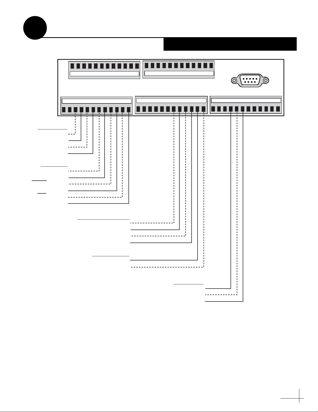
H
Wiring Diagrams
ADCU Wiring - Optional
Serial Port #1
Display Power
TX1A(+)
TX1B(-)
Ground
Sine/Cosine
Ground
Ref. V oltage
Cosine (inverted)
Cosine
Sine (inverted)
Sine
60 59 505152535455 49565758
Green Label
12 1110987612543
Duplicate Serial Port #1
KVH Display Power
Ground
TX1B(-)
TX1A(+)
48 47 383940414243 37444546
13 14 232221201918 24171615
Red LabelYellow Label
White LabelBlue Label
25 26 353433323130 36292827
GPS/Ship’s Gyro
GPS B- or HDG B-
GPS A+ or HDG A+
Serial Port #2
Ground
TX2B(-)
TX2A(+)
47
Page 47
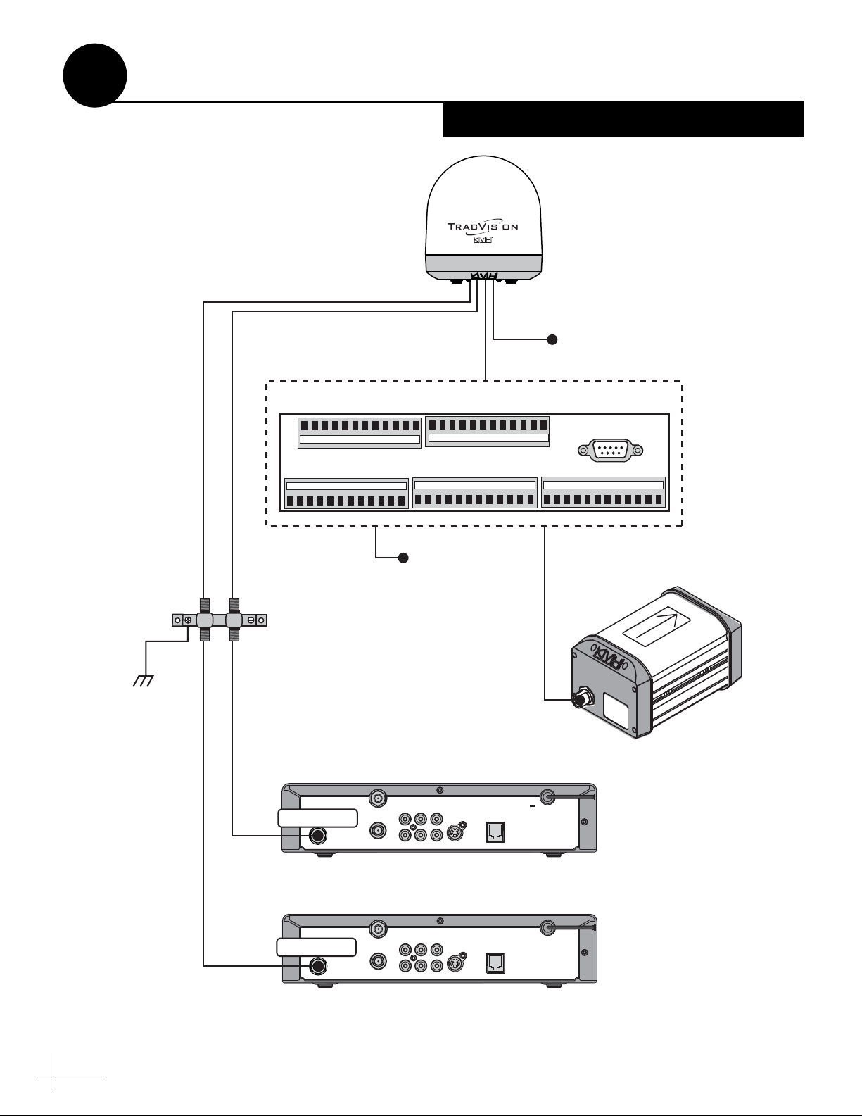
H
Data Power
+12 VDC
Vessel Power
SATELLITE IN
OUT TO TV
TV ANT/CABLE IN
AUDIO VIDEO S-VIDEO PHONE JACK
RL
Secondary Receiver - Optional
Primary Receiver (controls satellite selection)
SATELLITE IN
OUT TO TV
TV ANT/CABLE IN
AUDIO VIDEO S-VIDEO PHONE JACK
RL
Satellite In
Satellite In
ADCU
TracVision
Antenna
RF1
RF2
(Optional)
+12 VDC
Vessel Power
Sensor
13 14 232221201918 24171615
12 1110987612543
Green Label
48 47 383940414243 37444546
60 59 505152535455 49565758
Red LabelYellow Label
25 26 353433323130 36292827
White LabelBlue Label
Refer to ADCU Wiring Diagram
Vessel
AC Ground
Grounding
Block
Gro
und
Wire
RF2
(Optional)
RF1
Wiring Diagrams
Basic Wiring - Circular/Sky
48
Page 48

Data
ADCU
TracVision
Antenna
+12 VDC
Vessel Power
Sensor
13 14 232221201918 24171615
12 1110987612543
Green Label
48 47 383940414243 37444546
60 59 505152535455 49565758
Red LabelYellow Label
25 26 353433323130 36292827
White LabelBlue Label
Refer to ADCU Wiring Diagram
SATELLITE IN
OUT TO TV
TV ANT/CABLE IN
AUDIO VIDEO S-VIDEO PHONE JACK
RL
SATELLITE IN
OUT TO TV
TV ANT/CABLE IN
AUDIO VIDEO S-VIDEO PHONE JACK
RL
Fourth Receiver - Optional
Satellite In
RF4
(Optional)
SATELLITE IN
OUT TO TV
TV ANT/CABLE IN
AUDIO VIDEO S-VIDEO PHONE JACK
RL
Third Receiver - Optional
Satellite In
SATELLITE IN
OUT TO TV
TV ANT/CABLE IN
AUDIO VIDEO S-VIDEO PHONE JACK
RL
Second Receiver - Optional
Satellite In
Primary Receiver (controls satellite selection)
Satellite In
RF2
(Optional)
RF1
RF3
(Optional)
Quad LNB
Only
Power
+12 VDC
Vessel Power
H
Wiring Diagrams
Basic Wiring - Linear
49
Page 49

8.87"
(225 mm)
7.62"
(194 mm)
.63"
(16 mm)
3.08"
(78 mm)
1.83"
(46 mm)
.63"
4x .136" (3.45 mm)
4x R .63" (16 mm)
ADCU Flush Mounting Template
51
Page 50

www.kvh.com
KVH Industries, Inc.
Middletown, RI U.S.A.
Tel: +1 401 847 3327
Fax: +1 401 849 0045
E-mail: info@kvh.com
KVH Europe A/S
Kokkedal, Denmark
Tel: +45 45 160 180
Fax: +45 45 160 181
E-mail: info@kvh.dk
KVH Norway AS
Horten, Norway
Tel: +47 33 03 05 30
Fax: +47 33 03 05 31
E-mail: commboxsales@kvh.com
KVH Singapore
Singapore
Tel: +65 6829 2343
Fax: +65 6829 2121
E-mail: infokvhsingapore@kvh.com
 Loading...