

Page 1
TracVision M3DX Conversion System Instructions
To configure the system for circular signals, you will need to wire
the system differently from the wiring diagrams shown in the
Installation Guide and User’s Guide. Your conversion system comes
with a linear interface box, which gives you the flexibility to
simply add a destacker for circular use. Be sure to read these
special instructions for complete details.
IMPORTANT!
IMPORTANT! Special Instructions for the
TracVision M3DX Conversion System (01-0279-05)
You have purchased a special TracVision® M3DX conversion system
that can be configured for either circular or linear satellite signals.
These instructions explain how to configure the system for your
desired satellite(s). For example, if you travel from the U.S. to Mexico,
refer to these instructions to convert the system from a circular
configuration to a linear configuration.
Tools Required
• #2 Phillips-head screwdriver
• 7/16" open-end wrench
Table of Contents
Overview of Circular and Linear Configurations..........................................2
Configuring for Circular Signals, Out of the Box .........................................3
Converting from Circular to Linear..............................................................4
Converting from Linear to Circular............................................................10
Modified Wiring Diagrams for Circular Signals.........................................15
Wiring Diagram for Linear Signals ............................................................16
• Cutting pliers
• Flashlight
54-0390 Rev. B
1
Page 2
TracVision M3DX Conversion System Instructions
Circular Configuration
(Out of the Box)
Linear Configuration
(After Conversion)
Circular LNB
Inside
Antenna
Linear Interface Box
Destacker
North American Receiver
DIRECTV, DISH, or ExpressVu
Sky Mexico Receiver
Antenna
Linear Interface Box
Linear LNB
Inside
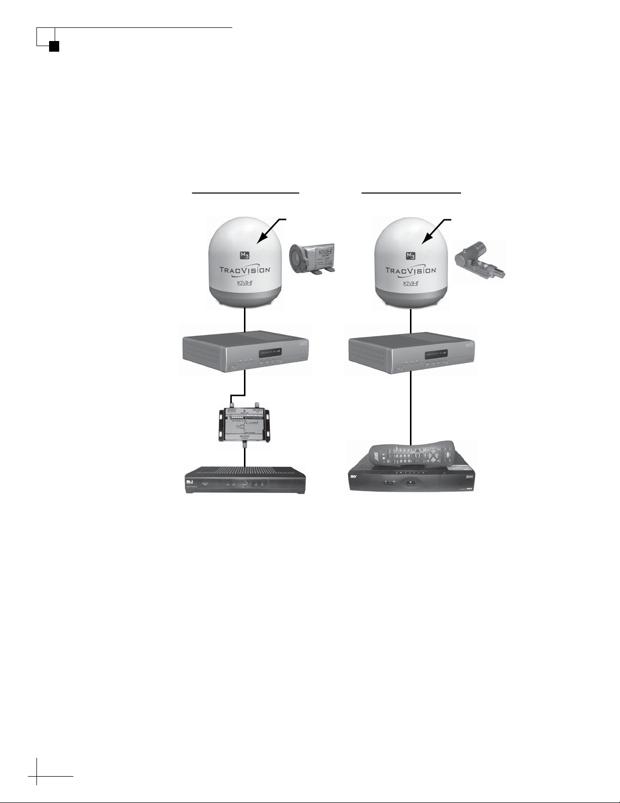
Overview of Circular and Linear Configurations
The diagram below illustrates the differences between circular and
linear configurations using the conversion system.
Figure 1 Circular and Linear Configurations
If you want to receive signals from a North American satellite, such as
DIRECTV, DISH Network, or ExpressVu, a circular LNB (Low Noise
Block) must be installed in the antenna and a destacker must be
connected between the interface box and your receiver. The destacker
is necessary because, unlike a circular interface box, your conversion
system’s linear interface box does not convert stacked signals into
unstacked signals. North American receivers can decode only
unstacked signals.
If you want to receive signals from the Sky Mexico satellite, a linear
LNB must be installed in the antenna. No destacker is necessary
because your conversion system is equipped with a linear interface
box.
2
Page 3
TracVision M3DX Conversion System Instructions
SATELLITE IN
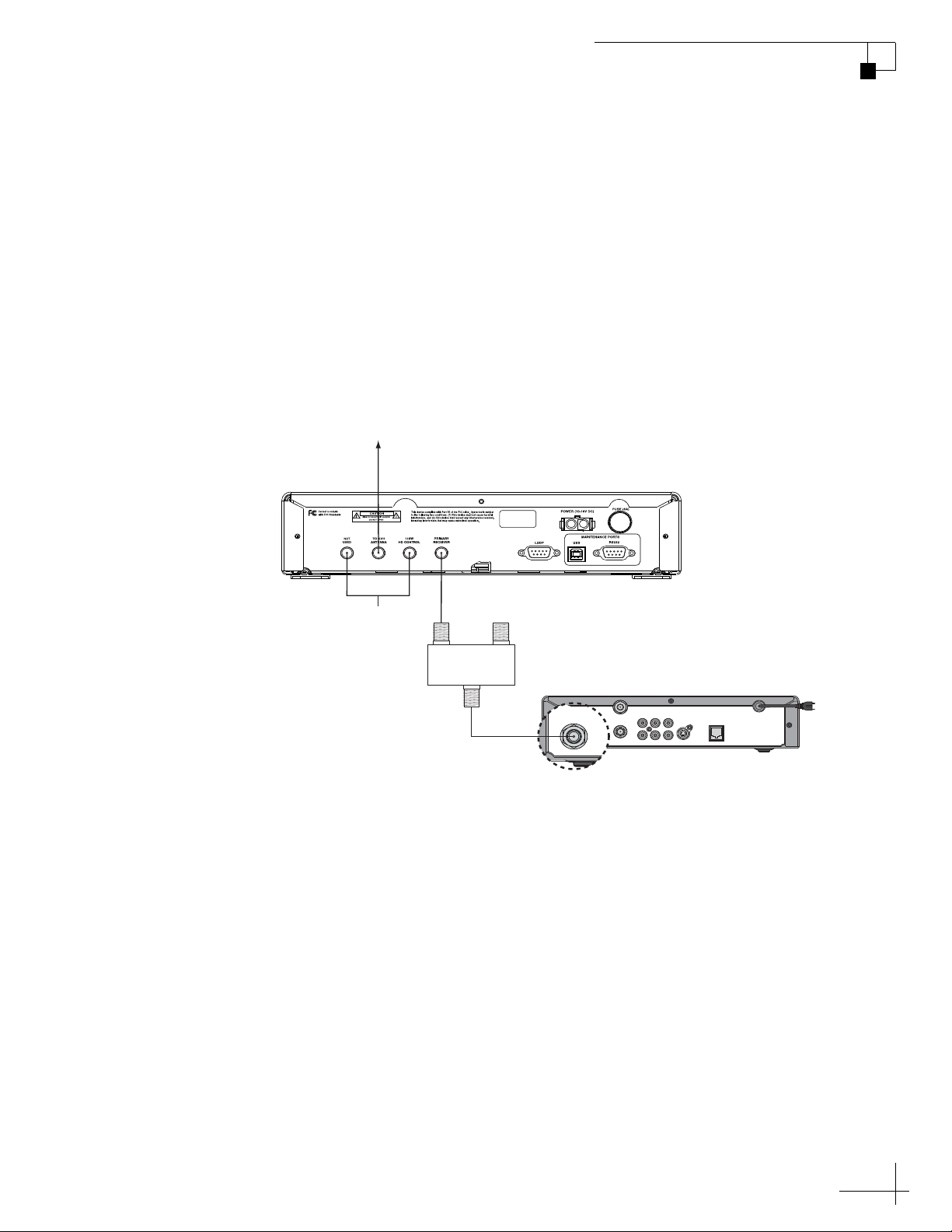
Configuring for Circular Signals, Out of the Box
(Valid for DIRECTV®, DISH Network®, and ExpressVu services)
Your TracVision M3DX antenna comes preconfigured for circular
signals using a linear interface box. All you need to do differently from
a standard circular system installation is connect the supplied
destacker between the linear interface box and your satellite TV
receiver, as shown in the wiring diagram below. The destacker
converts this stacked signal into an unstacked signal, which standard
North American receivers can decode.
Figure 2 Wiring Diagram for DIRECTV, DISH Network, or ExpressVu (Circular Receiver)
To Antenna
Linear Interface Box
Not Used
Destacker
(Supplied in Kit)
INPUT To TV
D575P
OUTPUT / To RECEIVER
Satellite TV Receiver (Primary)
TV ANT/CABLE IN
RL
SATELLITE IN
OUT TO TV
AUDIO VIDEO S-VIDEO PHONE JACK
NOTE: For details on wiring an optional Tri-Sat AutoSwitch for DIRECTV
Ku-band Tri-Sat service, refer to the instructions that came with the Tri-Sat
AutoSwitch kit.
3
Page 4
TracVision M3DX Conversion System Instructions
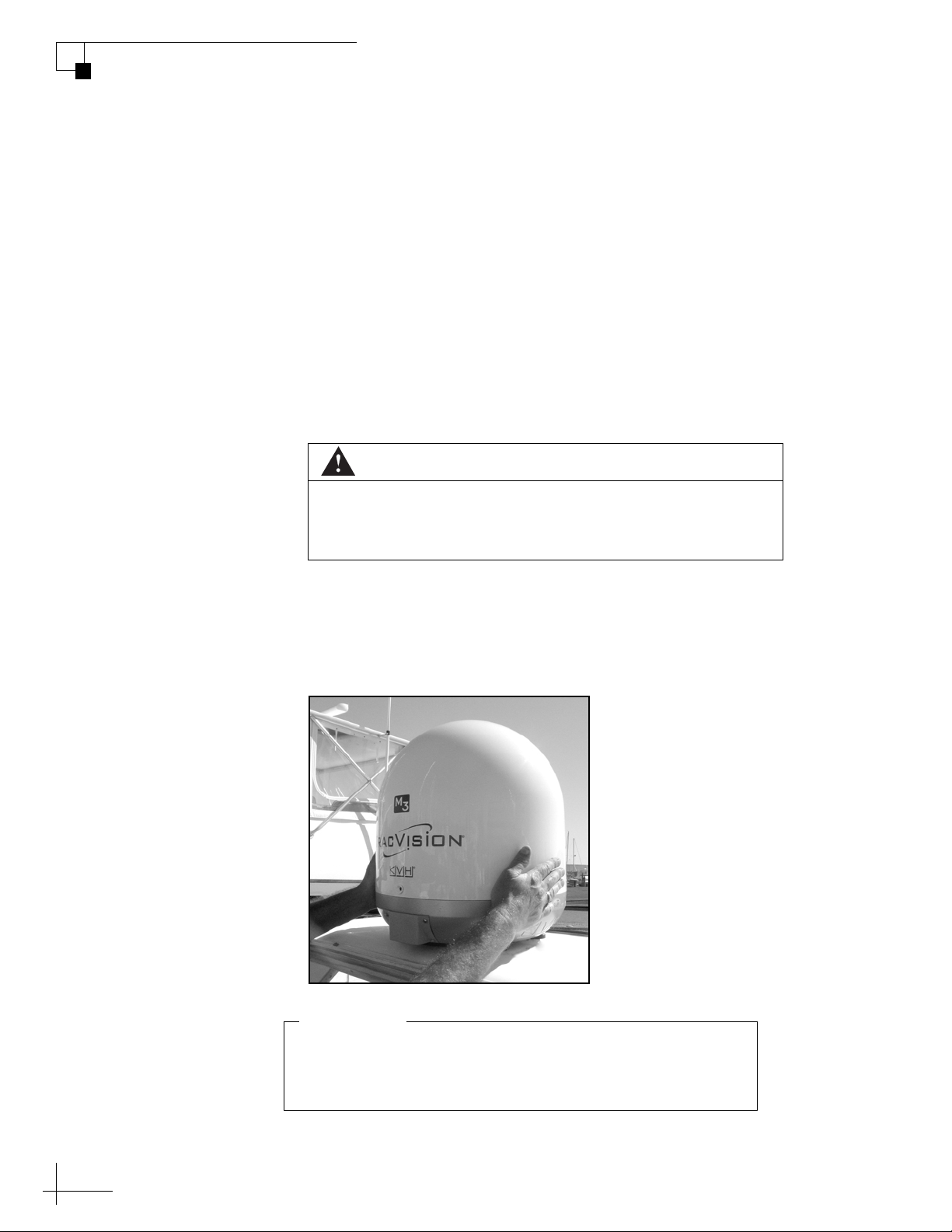
Do not grasp the reflector at any time during this
procedure. A warped reflector can significantly reduce
antenna performance.
IMPORTANT!
Converting from Circular to Linear
(Valid for Sky Mexico service)
The TracVision system comes from the factory configured for circular
satellite signals. If you wish to receive Sky Mexico signals instead,
follow the steps below to convert the system to a linear configuration.
1. Turn off and unplug your satellite TV receiver, if it is
connected to the TracVision system.
2. Press the Power switch on the front of the TracVision
interface box to turn off the TracVision system. Make
sure the VOLTAGE light goes out.
Disconnect power from the antenna before you remove the
radome. The antenna has moving parts that can cause
injury.
CAUTION
3. Remove the three #10-32 Phillips screws securing the
radome to the antenna.
4. Carefully remove the radome and set it aside in a safe place.
Figure 3 Removing the Radome
4
Page 5
TracVision M3DX Conversion System Instructions
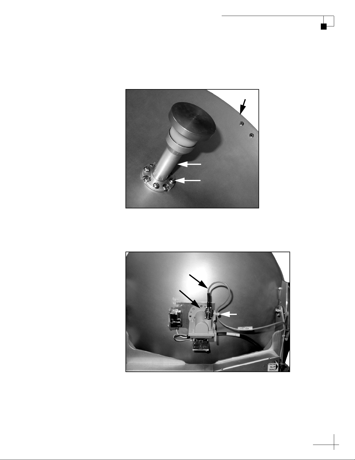
Feed Tube
#8 Screw (1 of 8)
Reflector
RF Cable
LNB
Tie-wrap
5. Remove the four #8 Phillips screws securing the feed
tube to the reflector. Remove the feed tube and set it
aside in a safe place.
Figure 4 Feed Tube
6. Using a 7/16" wrench, carefully disconnect the RF cable
from the circular LNB on the back of the reflector.
Figure 5 Circular LNB
7. Cut the tie-wrap securing the RF cable to the LNB. Be
careful not to cut the RF cable while you are cutting
the tie-wrap.
5
Page 6

TracVision M3DX Conversion System Instructions
Be sure to orient the choke feed so that the zero (0) mark on
its skew angle label is centered at the top (see Figure 6).
IMPORTANT!
Linear
Zero Skew Angle
Gyro Bracket
Choke Feed
8. Remove the four remaining #8 Phillips screws securing
the gyro bracket and LNB to the reflector. Save the
circular LNB for future use.
9. Place the gyro bracket and linear choke feed against the
reflector as shown in the figure below. Align all holes in
the choke feed, gyro bracket, and reflector.
Figure 6 Positioning the Gyro Bracket and Linear Choke Feed
10. While holding the choke feed and gyro bracket in place,
insert the four shorter (1/2") #8 Phillips screws in a
cross pattern from the front side of the reflector. Handtighten the screws.
Figure 7 Cross Pattern of Screws to Secure Gyro Bracket/Choke Feed
6
Page 7

TracVision M3DX Conversion System Instructions
LNB
Wing Screw
(1 of 2)
11. Attach the feed tube to the reflector, gyro bracket, and
choke feed using the four long (3/4") #8 Phillips screws.
Hand-tighten the screws (see Figure 4 on page 5).
12. Tighten all eight screws evenly in an alternating
manner to prevent cross-threading. Tighten the shorter
screws first, then tighten the longer feed tube screws.
13. Insert the linear LNB into the choke feed as far as it will
go. Don’t worry about setting the skew; you will adjust
it later.
Figure 8 Inserting the Linear LNB into the Choke Feed
14. Secure the LNB to the choke feed with the two supplied
wing screws.
Figure 9 Tightening the Wing Screws
7
Page 8

TracVision M3DX Conversion System Instructions
RF Cable
Tie-wrap
Voltage Switch
15. Connect the RF cable to the LNB. Hand-tighten, then
tighten with a 7/16" wrench for 1/4 turn.
Figure 10 Connecting the RF Cable to the LNB
16. Using a tie-wrap, secure the RF cable to the LNB body.
Be sure to maintain an adequate bend radius in the
cable, as shown in the figure above.
17. Using your finger or a non-metallic tool, set the voltage
switch on the circuit board fully to the LEFT to the
“Linear 13V-18V” position.
Figure 11 Voltage Switch on Circuit Board
8
Page 9

TracVision M3DX Conversion System Instructions
Be sure to adjust the antenna’s LNB to the correct skew angle, as
described in the User’s Guide. Unlike circular signals, which are
transmitted in a corkscrew pattern, linear signals are transmitted in
a precise cross pattern. Therefore, the LNB needs to be oriented in
the same manner to optimize reception.
IMPORTANT!
Figure 12 Voltage Switch, Close-up
18. Disconnect the destacker from the belowdecks interface
box, if you have one connected. In a linear
configuration, you can connect your Sky Mexico linear
receiver directly to the “Primary Receiver” output on
the interface box. No destacker is necessary.
19. Plug in and turn on your satellite TV receiver.
20. Press the Power switch on the front of the TracVision
interface box to turn on the TracVision system.
21. Follow the instructions in Chapter 4 of the User’s Guide
(Linear Configuration) to set up the TracVision system
for your desired satellites and set the LNB skew angle.
22. Reattach the radome and secure in place using the three
#10-32 Phillips screws you removed earlier.
9
Page 10

TracVision M3DX Conversion System Instructions
Do not grasp the reflector at any time during this
procedure. A warped reflector can significantly reduce
antenna performance.
IMPORTANT!
Converting from Linear to Circular
(Valid for DIRECTV, DISH Network, and ExpressVu services)
If you converted the system previously to a linear configuration and
now wish to receive North American satellite TV signals, follow the
steps below to convert the system back to a circular configuration.
1. Turn off and unplug your satellite TV receiver, if it is
connected to the TracVision system.
2. Press the Power switch on the front of the TracVision
interface box to turn off the TracVision system. Make
sure the VOLTAGE light goes out.
Disconnect power from the antenna before you remove the
radome. The antenna has moving parts that can cause
injury.
CAUTION
3. Remove the three #10-32 Phillips screws securing the
radome to the antenna.
4. Carefully remove the radome and set it aside in a safe place.
Figure 13 Removing the Radome
10
Page 11

TracVision M3DX Conversion System Instructions
Feed Tube
#8 Screw (1 of 8)
Reflector
RF Cable
LNB
Tie-wrap
5. Remove the four #8 Phillips screws securing the feed
tube to the reflector. Remove the feed tube and set it
aside in a safe place.
Figure 14 Feed Tube
6. Using a 7/16" wrench, carefully disconnect the RF cable
from the linear LNB on the back of the reflector.
Figure 15 Linear LNB
11
Page 12

TracVision M3DX Conversion System Instructions
Be sure to orient the LNB so that the RF connector is facing
upward (see Figure 16).
IMPORTANT!
LNB
Gyro
Bracket
Connector
7. Cut the tie-wrap securing the RF cable to the LNB (see
Figure 15 on page 11). Be careful not to cut the RF
cable while you are cutting the tie-wrap.
8. Remove the four remaining #8 Phillips screws securing
the gyro bracket and LNB choke feed to the reflector.
Save the linear choke feed and LNB for future use.
9. Place the gyro bracket and circular LNB against the
reflector as shown in the figure below. Align all holes in
the LNB, gyro bracket, and reflector.
Figure 16 Positioning the Gyro Bracket and Circular LNB
10. While holding the gyro bracket and LNB in place, insert
and hand-tighten the four shorter (1/2") #8 Phillips
screws in a cross pattern from the front of the reflector.
Figure 17 Cross Pattern of Screws to Secure Gyro Bracket/LNB
12
Page 13

TracVision M3DX Conversion System Instructions
RF Cable
LNB
Tie-wrap
11. Attach the feed tube to the reflector, gyro bracket, and
LNB using the four longer (3/4") #8 Phillips screws.
Hand-tighten the screws (see Figure 14 on page 11).
12. Tighten all eight screws evenly in an alternating
manner to prevent cross-threading. Tighten the shorter
screws first, then tighten the longer feed tube screws.
13. Connect the RF cable to the LNB. Hand-tighten, then
tighten with a 7/16" wrench for 1/4 turn.
Figure 18 Connecting the RF Cable to the LNB
14. Using a tie-wrap, secure the RF cable to the LNB body.
Be sure to maintain an adequate bend radius in the
cable, as shown in Figure 18.
13
Page 14

TracVision M3DX Conversion System Instructions
Voltage Switch
15. Using your finger or a non-metallic tool, set the voltage
switch on the circuit board fully to the RIGHT to the
“Circular 8V” position.
Figure 19 Voltage Switch on Circuit Board
Figure 20 Voltage Switch, Close-up
16. Reattach the radome and secure in place using the three
#10-32 Phillips screws you removed earlier.
17. Connect a destacker between the interface box and your
North American circular receiver, as described in the
next section. Then plug in and turn on your receiver.
18. Press the Power switch on the front of the interface box
to turn on the TracVision system.
14
19. Follow the steps in Chapter 4 of the User’s Guide
(Circular Configuration) to set up the system.
Page 15

TracVision M3DX Conversion System Instructions
Unlike a standard circular interface box, your special linear
interface box does not include a second output for connecting a
second receiver. The satellite signal is only available at the
“Primary Receiver” jack on the linear interface box.
IMPORTANT!
To Antenna
SATELLITE IN
OUT TO TV
TV ANT/CABLE IN
AUDIO VIDEO S-VIDEO PHONE JACK
RL
SATELLITE IN
Satellite TV Receiver (Primary)
Linear Interface Box
Destacker
(Supplied in Kit)
INPUT To TV
OUTPUT / To RECEIVER
Not Used
D575P
Modified Wiring Diagram for Circular Signals
(Valid for DIRECTV, DISH Network, and ExpressVu services)
Your TracVision conversion system includes a special linear interface
box that offers the flexibility to be used in either a circular or linear
configuration. For circular configurations, you will need to install a
destacker between the interface box and your receiver. Therefore, the
wiring diagrams provided in the User’s Guide are not entirely correct
for your system. Refer to the modified wiring diagram below to
connect your receiver.
Wiring One Standard Circular (N. American) Receiver
NOTE: For details on wiring an optional Tri-Sat AutoSwitch for DIRECTV
Ku-band Tri-Sat service, refer to the instructions that came with the Tri-Sat
AutoSwitch kit.
15
Page 16

TracVision M3DX Conversion System Instructions
To Antenna
SATELLITE IN
OUT TO TV
TV ANT/CABLE IN
AUDIO VIDEO S-VIDEO PHONE JACK
RL
SATELLITE IN
Satellite TV Receiver (Primary)
Linear Interface Box
Not Used
Wiring Diagram for Linear Signals
(Valid for Sky Mexico service)
The wiring for a linear configuration remains the same as presented in
the User’s Guide. No destacker is required.
Wiring One Standard Linear (Sky Mexico) Receiver
16
 Loading...