

Page 1

TracVision M3 User’s Guide
TracVision M3 – DX Version
Linear Configuration
Page 2
TracVision M3
DX Version - Linear
User’s Guide
This user’s guide provides all of the basic information you need to
operate, set up, and troubleshoot the TracVision M3 satellite TV
antenna system. For detailed system installation information,
please refer to the TracVision M3 Installation Guide.
TracVision M3 User’s Guide
Please direct questions, comments, or suggestions to:
KVH Industries, Inc. KVH Europe A/S
50 Enterprise Center Kokkedal Industripark 2B
Middletown, RI 02842-5279 USA 2980 Kokkedal, Denmark
Tel: +1 401 847-3327 Tel: +45 45 160 180
Fax: +1 401 849-0045 Fax: +45 45 160 181
E-mail: info@kvh.com E-mail: info@kvh.dk
Internet: www.kvh.com Internet: www.kvh.com
If you have any comments regarding this manual, please e-mail
them to manuals@kvh.com. Your input is greatly appreciated!
KVH Part # 54-0385-01 Rev. B
© 2006, KVH Industries, Inc., All rights reserved.
U.S. Patents Pending
Page 3

TracVision and KVH are registered trademarks of KVH Industries, Inc.
The unique light-colored dome with dark contrasting base is a registered trademark of KVH Industries, Inc.
DVB (Digital Video Broadcasting) is a registered trademark of the DVB Project.
All other trademarks are the property of their respective owners.
Page 4

Table of Contents
1Introduction
Using this Manual ..............................................................................3
TracVision M3 System Overview........................................................5
Linear Satellite Signals ......................................................................6
2Operation
Receiving Satellite TV Signals..........................................................11
TracVision M3 User’s Guide
Table of Contents
Turning the System On/Off ..............................................................12
System Startup ................................................................................13
Understanding the Status Screen ....................................................15
Switching Satellites .........................................................................16
3 System Preferences
Adjusting the Display Brightness .....................................................21
Entering Latitude/Longitude ............................................................22
4Setup
Selecting Satellites to Track ............................................................27
Setting the LNB Skew Angle ............................................................31
Resetting the System to Change Setup ...........................................34
5 Troubleshooting
Five Simple Checks..........................................................................39
System Status Lights .......................................................................40
Running the Diagnostics Test ..........................................................42
i
Page 5

TracVision M3 User’s Guide
Table of Contents
A Wiring Diagram
B Menus Quick Reference Guide
Viewing System Information............................................................46
Changing the Satellite Switching Mode...........................................49
Calibrating the Gyros .......................................................................51
Changing Tracking Parameters .......................................................53
Technical Support............................................................................57
Product Care ....................................................................................58
Wiring Diagram ................................................................................61
Interface Box Menus........................................................................65
C Programming User-Defined Satellites
Connecting a Laptop to the Antenna................................................69
Programming Your User-Defined Satellites .....................................71
ii
Page 6

1. Introduction
This chapter provides a basic overview of this manual and your
TracVision system.
Contents
Using this Manual.............................................................. 3
TracVision M3 System Overview ....................................... 5
Linear Satellite Signals...................................................... 6
TracVision M3 User’s Guide
Chapter 1 - Introduction
1
Page 7
Using this Manual
This manual provides complete operation, setup, and troubleshooting
information for your TracVision system.
Who Should Use This Manual
The user should refer to the “Operation” and “System Preferences”
chapters to learn how to operate the system using the interface box.
The user or installer should refer to the “Setup” chapter and “Wiring
Diagrams” appendix for information on configuring the system for the
desired satellite(s).
The user and/or servicing technician should refer to the
“Troubleshooting” chapter to help identify the cause of a system
problem.
TracVision M3 User’s Guide
Chapter 1 - Introduction
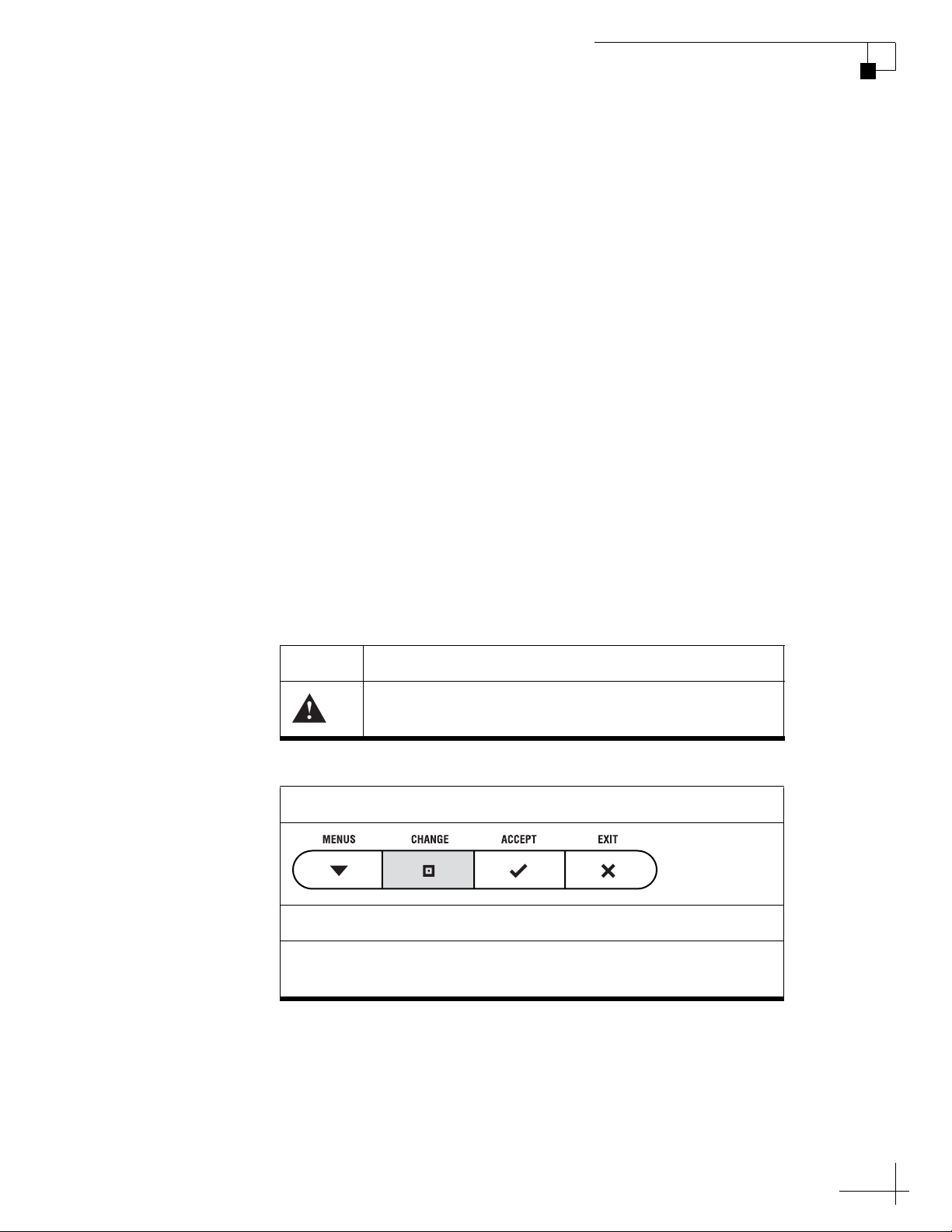
Icons Used in this Manual
This manual uses the following icons to call attention to important
information:
Icon Description
Icon
Description
This is an illustration of the buttons on the interface box. Gray
shading indicates which button the user should press.
This is a danger, warning, or caution notice. Be sure
to read these carefully to avoid injury!
3
Page 8
TracVision M3 User’s Guide
Chapter 1 - Introduction
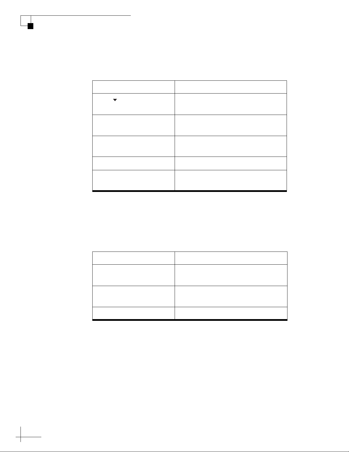
Typographical Conventions
This manual uses the following typographical conventions:
Text Example Description
Press MENUS to view
the menu
SELECT SATELLITES Text as it appears on the interface box
The display shows
“BRIGHTNESS”
<Satellite name> Brackets indicate a variable value
See “Switching Satellites”
on page 16
Related Documentation
In addition to this User’s Guide, the following documents are
provided with your TracVision system:
Document Description
Both the icon and the name of the
button are provided.
display
Text in quotes is shown on the
interface box display
Cross-reference to another chapter in
the manual or to a web site
Installation Guide Complete product installation
instructions
Quick Start Guide Handy quick reference to basic
operation and setup
Contents List List of every part supplied in the kit
4
Page 9
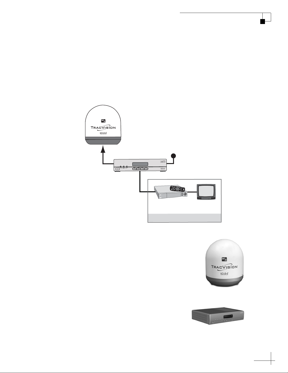
TracVision M3 System Overview
Your TracVision M3 system is a state-of-the-art, actively stabilized
antenna system that delivers live satellite TV to your vessel’s audio/
video entertainment system. A basic system is illustrated below. A
receiver wiring diagram is provided in Appendix A on page 59.
Figure 1-1 TracVision M3 System Diagram
Antenna
TracVision M3 User’s Guide
Chapter 1 - Introduction
Interface Box
Satellite Receiver TV
Options Purchased Separately
The antenna uses integrated DVB technology to
quickly acquire and track the correct satellite,
switch between satellites, and send TV signals to
the interface box. Internal gyros allow the antenna
to track the satellite at all times, even while you’re
on the move! And its advanced 37 cm (14.5")
antenna design delivers signal strength, reception,
and coverage comparable to larger 45 cm (18")
antennas.
Vessel Power
12 VDC
The interface box allows you to set up and
control the system using its four
pushbuttons and LCD display. It also
supplies power to the antenna and delivers
satellite TV signals to your satellite TV receiver.
5
Page 10

TracVision M3 User’s Guide
Chapter 1 - Introduction
Linear Satellite Signals
Your TracVision system is configured to receive linearly polarized
satellite signals. Satellites around the world (with the exception of
satellites in North America, which transmit circularly polarized
signals) transmit linear signals in vertical and horizontal “waves” that
are offset exactly 90º from each other. This orientation doubles the
bandwidth, allowing the satellite to deliver hundreds of channels of
digital entertainment to your vessel.
Figure 1-2 Linearly Polarized Satellite Signals
LNB Skew Angle
Since linear satellite signals are oriented in a precise cross pattern, the
TracVision antenna’s receiving element, called an LNB (low-noise
block) must be oriented in the same way to optimize reception. This
orientation adjustment is referred to as the LNB’s “skew angle.” The
figure below illustrates how skew determines the amount of signal the
LNB collects. The more signal, the better the reception.
Figure 1-3 How Skew Works
Ideal SkewGood SkewBad Skew
= Satellite Signal = LNB "Signal Collector"
6
Page 11
TracVision M3 User’s Guide
Chapter 1 - Introduction
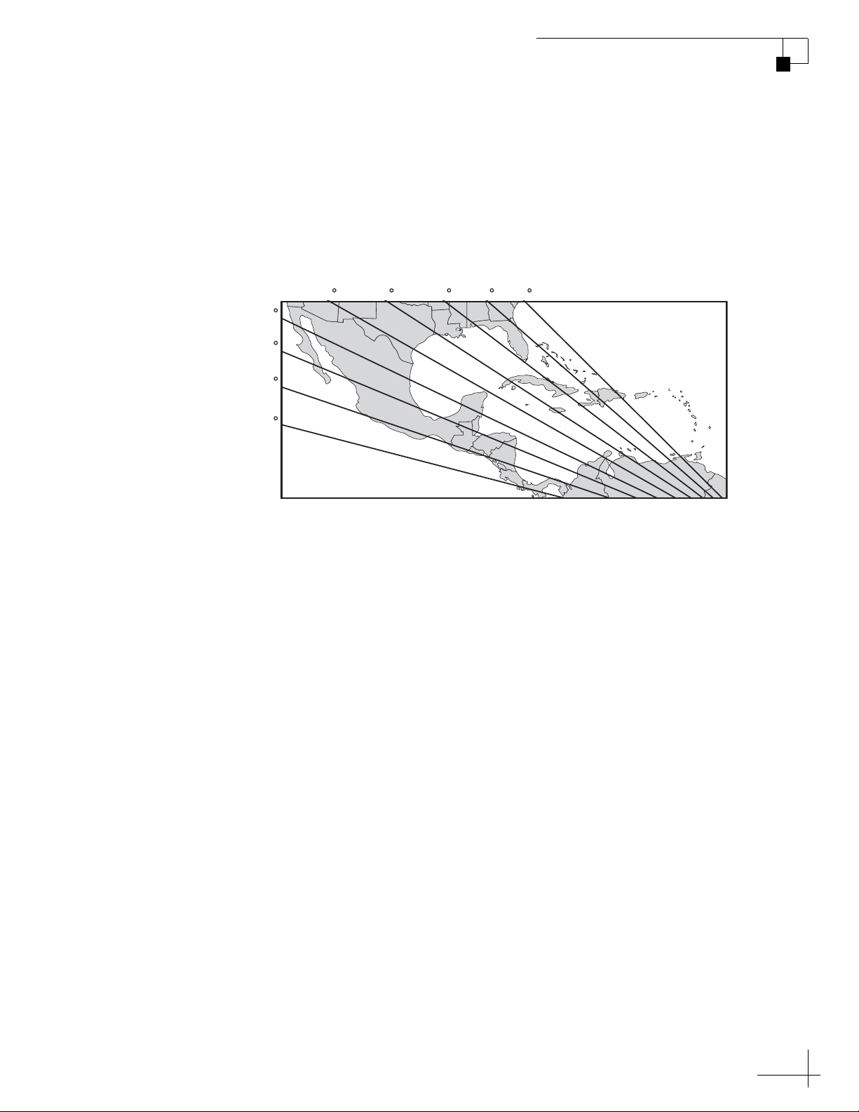
The correct skew setting varies depending on your geographic
location, since the orientation of your antenna to the satellite changes
as you move. For example, as shown in the figure below, if your
antenna is tracking the PAS 9 satellite for Sky Mexico programming,
the ideal skew setting ranges from +30 to +70, depending upon where
you’re located within the satellite’s coverage area.
Figure 1-4 Approximate Skew Settings for the PAS 9 Satellite
+50 +45 +40 +35 +30
+55
+60
+65
+70
For complete details about adjusting the LNB’s skew, see “Setting the
LNB Skew Angle” on page 31.
7
Page 12

2. Operation
This chapter explains how to use the interface box to operate the
TracVision system. It explains how to turn the TracVision system on or
off, interpret the startup screens, and switch between satellites.
Contents
Receiving Satellite TV Signals ......................................... 11
Turning the System On/Off .............................................. 12
System Startup................................................................ 13
Understanding the Status Screen.................................... 15
TracVision M3 User’s Guide
Chapter 2 - Operation
Switching Satellites......................................................... 16
9
Page 13

Receiving Satellite TV Signals
Television satellites are located in fixed positions above the Earth’s
equator and beam TV signals down to certain regions of the planet
(not worldwide). To receive TV signals from a satellite, you must be
located within that satellite’s unique coverage area.
TIP: For your convenience, KVH provides links to several web sites that offer
satellite coverage information. Simply visit our web site at www.kvh.com/
footprint.
Figure 2-1 Location of Astra1 Satellite
TracVision M3 User’s Guide
Chapter 2 - Operation
Equator
In addition, since TV satellites are located above the equator, the
TracVision antenna must have a clear view of the sky to receive
satellite TV signals. Anything that stands between the antenna and the
satellite can block the signal, resulting in lost reception. Common
causes of blockage include trees, buildings, and bridges. Heavy rain,
ice, or snow may also temporarily interrupt satellite signals.
Figure 2-2 Example of Satellite Blockage
TracVision
11
Page 14
TracVision M3 User’s Guide
Chapter 2 - Operation
Turning the System On/Off
Since the interface box supplies power to the antenna, you can turn the
antenna on or off using the interface box POWER switch.
Turning On the System
Follow the steps below to turn on your TracVision system.
1. Make sure the antenna has a clear view of the sky.
2. Turn on your satellite TV receiver and TV.
3. Press the POWER switch on the front of the
TracVision interface box.
4. Wait one minute for system startup.
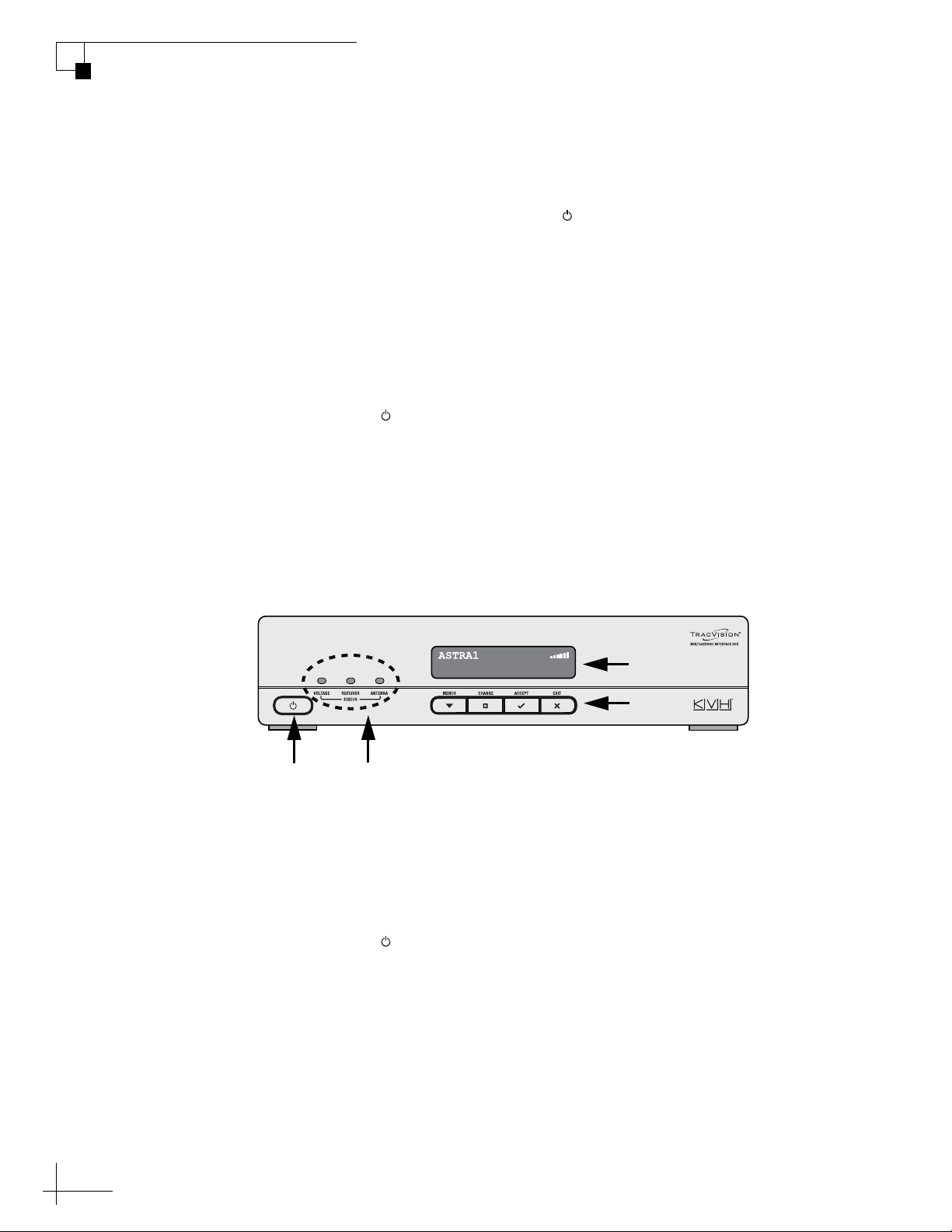
Once the antenna finds the correct satellite, all three status lights on
the interface box should be lit green. If any lights are not lit green, refer
to “System Status Lights” on page 40.
Figure 2-3 Interface Box Components
Power
Switch
Turning Off the System
Follow the steps below to turn off the TracVision system.
1. Press the POWER switch on the front of the
TracVision interface box.
2. Turn off your satellite TV receiver and TV.
Display
Buttons
Status
Lights
12
Page 15
System Startup
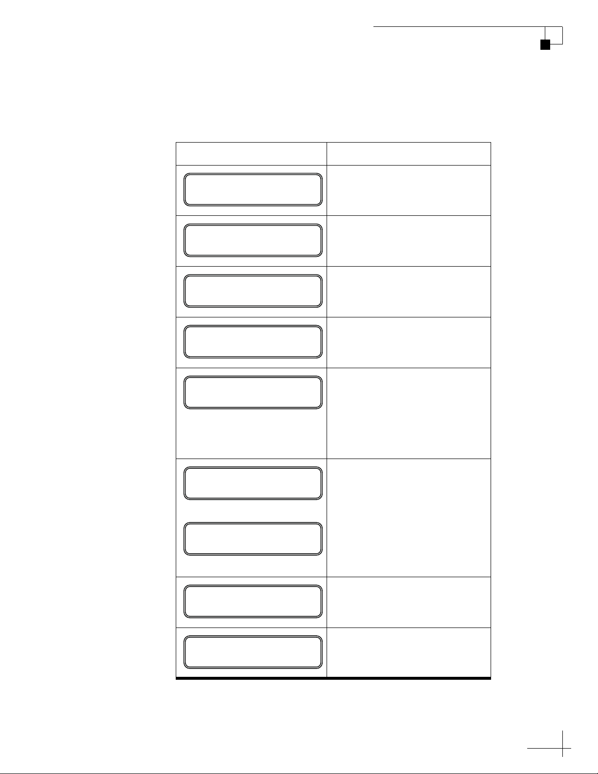
The display shows the following screens during startup.
Interface Box Screen Description
TracVision M3 User’s Guide
Chapter 2 - Operation
KVH INTERFACE BOX
VERSION X.YZ
KVH TRACVISION M3
SYS SW VERSION X.YZ
KVH TRACVISION M3
RF SW VERSION X.YZ
INSTALLED SATELLITES
HOTBIRD, THOR
LAT/LONG: 55N, 012E
Interface box software version
Antenna model and main
software version
Antenna RF software version
Satellite(s) installed for
tracking
Latitude and longitude that
you last set in the antenna (or
factory default lat/long); see
“Entering Latitude/Longitude”
on page 22 for details on
entering your position
HOTBIRD SKEW:-12.5
CHECK LNB SETTING
or
AVERAGE SKEW:-12.3
CHECK LNB SETTING
INITIALIZING ANTENNA
SEARCHING HOTBIRD
Recommended LNB skew
angle setting
If only one satellite is
installed, shows the ideal skew
for that satellite;
If multiple satellites are
installed, shows the average
skew for all installed satellites
Antenna performs self-test
Antenna searches for the
selected satellite
13
Page 16

TracVision M3 User’s Guide
Chapter 2 - Operation
Warning Messages on Startup
During startup, make sure none of the following warning messages
appear on the display.
to change your antenna setup to select a different set of satellites (see
“Resetting the System to Change Setup” on page 34), or you may
simply need to update the latitude/longitude stored in the antenna (see
“Entering Latitude/Longitude” on page 22).
Warning Description
If one of these messages appears, you may need
WARNING!
WIDE SKEW RANGE: 14
WARNING! SATELLITE
OUT OF ANTENNA RANGE
SYSTEM SAT MISMATCH
PRESS TO FIX
SAT NOT INSTALLED
The average skew may not
provide adequate reception for
all installed satellites. The
satellites are too far apart from
each other in the sky.
The antenna is not able to track
one of your installed satellites
because your vessel is not
located within that satellite’s
coverage area, based on the
latitude/longitude you have
set in the antenna.
The interface box and antenna
are out of sync. Just press
ACCEPT to synchronize.
The receiver is tuned to a
channel carried by a satellite
that is not installed in the
antenna.
14
Page 17
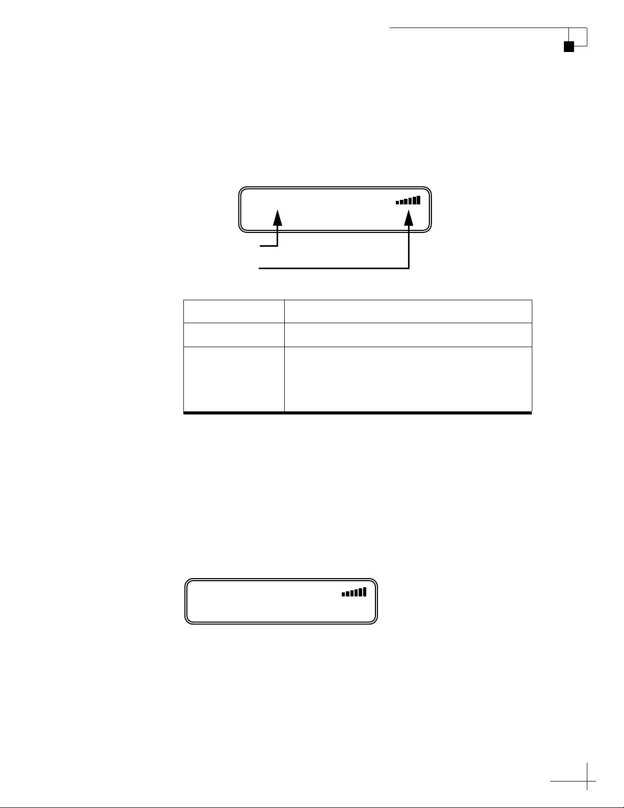
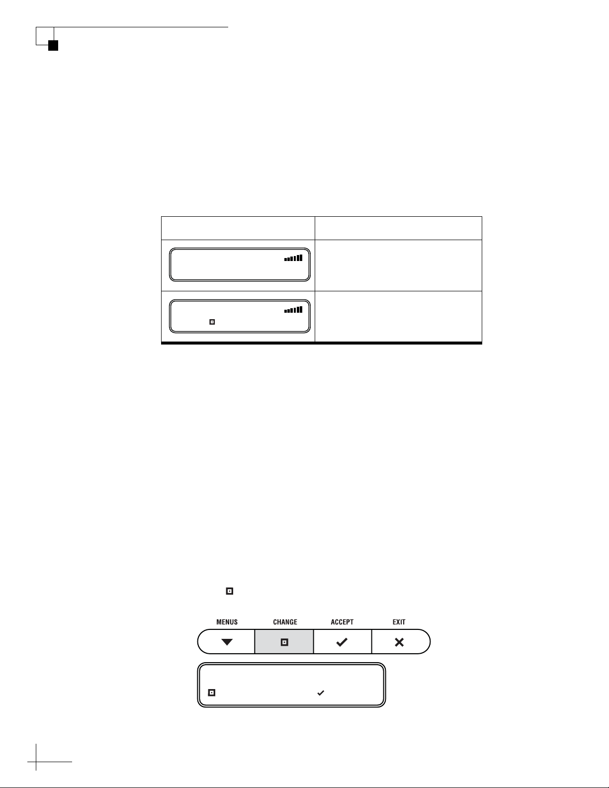
Understanding the Status Screen
Following startup, the interface box display shows the current system
status.
Figure 2-4 Interface Box Status Screen
ASTRA1
Satellite
Signal Strength
Screen Field Description
TracVision M3 User’s Guide
Chapter 2 - Operation
Satellite
Signal Strength Strength of the satellite TV signal, as measured
NOTE: If your system is set up for manual satellite switching, the status
screen differs somewhat. See the following page.
“System Needs Setup”
If the interface box shows “System Needs Setup,” the antenna system
has not yet been configured for the satellites you wish to track. See
“Selecting Satellites to Track” on page 27 for setup instructions.
Figure 2-5 “System Needs Setup” Screen
ASTRA1
SYSTEM NEEDS SETUP
Satellite that the antenna is currently tracking
by RF level
The more bars, the stronger the signal, just like a
cell phone. Three bars = good reception.
15
Page 18
TracVision M3 User’s Guide
Chapter 2 - Operation
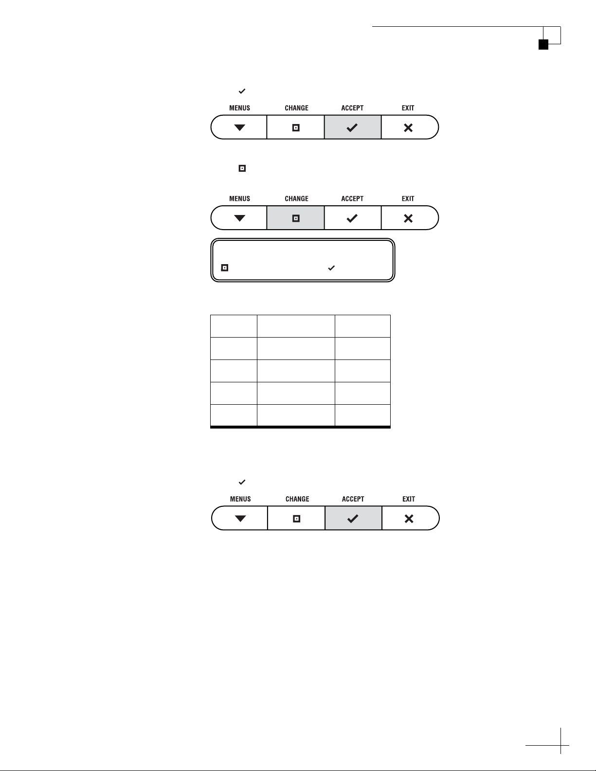
Switching Satellites
If your TracVision system is set up to track multiple satellites, you can
easily switch between them. For normal operation, keep the system set
to Automatic satellite switching (factory default). If you wish to
manually switch between satellites, see “Changing the Satellite
Switching Mode” on page 49.
switching method by the format of the status screen:
Status Screen Example Satellite Switching Method
You can identify the current satellite
ASTRA1
ASTRA1 HH
PUSH TO SWITCH SAT
TIP: Use Automatic switching for normal operation. Manual switching is
generally used for troubleshooting only.
Automatic Satellite Switching
If your system is set up for automatic switching, the antenna
automatically switches satellites as you change channels using the
receiver’s remote control. The antenna also automatically selects the
correct signal polarization and band for the selected channel.
Manual Satellite Switching
If you selected Manual switching, follow the steps below to use the
interface box to switch between satellites. You will also need to select
the correct polarization and band for the desired channel.
Automatic
Manual
16
1. Press CHANGE until the display shows the desired
satellite.
SATELLITE= HOTBIRD?
CHANGE ACCEPT
Page 19
TracVision M3 User’s Guide
Chapter 2 - Operation
2. Press ACCEPT.
3. Press CHANGE until the display shows the correct
polarization and band for the desired channel.
POLARIZATION/BAND=HL
CHANGE ACCEPT
There are four possible combinations of polarization/band:
Code Polarization Band
HL Horizontal Low
HH Horizontal High
VL Vertical Low
VH Vertical High
TIP: Polarization and band information for various channels is
available at www.lyngsat.com (site not affiliated with KVH).
4. Press ACCEPT.
The antenna switches to the selected satellite and polarization/
band.
NOTE: The antenna remains in manual switching mode until you
change it back to automatic switching. See “Changing the Satellite
Switching Mode” on page 49.
17
Page 20

TracVision M3 User’s Guide
Chapter 3 - System Preferences
3. System Preferences
This chapter explains how to change the settings for display brightness
and latitude/longitude. Refer to “Interface Box Menus” on page 65 for a
quick reference guide to accessing these functions within the menu.
Contents
Adjusting the Display Brightness..................................... 21
Entering Latitude/Longitude ............................................ 22
19
Page 21

Adjusting the Display Brightness
Follow the steps below to adjust the brightness of the interface box
display.
1. Press MENUS until the display shows
“BRIGHTNESS.”
BRIGHTNESS= HIGH
NEXT MENU CHANGE
2. Press CHANGE until the display shows the desired
setting: HIGH, MEDIUM, or LOW.
TracVision M3 User’s Guide
Chapter 3 - System Preferences
BRIGHTNESS= MEDIUM?
CHANGE ACCEPT
3. Press ACCEPT.
BRIGHTNESS= MEDIUM
4. Press EXIT to exit the menu.
21
Page 22

TracVision M3 User’s Guide
Chapter 3 - System Preferences
Entering Latitude/Longitude
Follow the steps below to enter your vessel’s latitude and longitude
into the system. The antenna will use your position information to
speed up satellite acquisition. (If the antenna knows where you are
located, it knows where it should start looking for the satellite.) The
antenna will also use this position information to calculate the correct
LNB skew angle.
KVH recommends that you re-enter your latitude/longitude
whenever you travel more than 600 km (400 mi) away from the last
position you entered. (The interface box displays the last entered
position during system startup.) Once you have entered a new
position following the steps below, check the updated skew angle that
the interface box displays during restart. If the reported skew angle
differs by more than 5 degrees from the LNB’s current skew angle,
you should adjust the antenna’s LNB to the new skew angle to
optimize satellite reception. See “Setting the LNB Skew Angle” on
page 31.
1. Press MENUS until the display shows “LAT/
LONG.”
LAT/LONG= 41N, 071W
NEXT MENU CHANGE
2. Press CHANGE.
LAT/LONG= 41N, 071W?
CHANGE ACCEPT
22
Page 23

TracVision M3 User’s Guide
Chapter 3 - System Preferences
3. Press CHANGE again. A cursor appears under the
first number in the displayed latitude.
LAT/LONG= 41N, 071W
CHANGE ACCEPT
4. Press CHANGE until the number is set to the first
digit of your vessel’s current latitude.
5. Press ACCEPT. The cursor moves to the next number.
LAT/LONG= 51N, 071W
CHANGE ACCEPT
6. Repeat steps 4 and 5 to set the remaining digits (plus
North/South and East/West directions) of your
latitude and longitude. Once you have set the entire
position, the cursor disappears from the display.
LAT/LONG= 55N, 012E?
CHANGE ACCEPT
7. Press ACCEPT. The antenna restarts. Wait one
minute for system startup.
23
Page 24

4. Setup
When you turn on the TracVision system for the first time, the interface
box display shows “SYSTEM NEEDS SETUP.” This chapter explains how
to set up your TracVision system for the satellite(s) you wish to track.
Contents
Selecting Satellites to Track............................................ 27
Setting the LNB Skew Angle............................................ 31
Resetting the System to Change Setup........................... 34
TracVision M3 User’s Guide
Chapter 4 - Setup
25
Page 25

Selecting Satellites to Track
Follow the steps below to set up the TracVision system to track the
satellites of your choice.
NOTE: If the status screen does not show “System Needs Setup,” follow the
steps in “Resetting the System to Change Setup” on page 34.
ASTRA1
SYSTEM NEEDS SETUP
1. Press any button to begin the setup process.
TracVision M3 User’s Guide
Chapter 4 - Setup
LAT/LONG= 41N, 071W?
CHANGE ACCEPT
2. The display shows “LAT/LONG.” Press CHANGE.
LAT/LONG= 41N, 071W
CHANGE ACCEPT
Now you need to enter your vessel’s latitude and longitude so
that the antenna can calculate the proper LNB skew setting for
your position. The antenna will also use this position
information to speed up satellite acquisition.
27
Page 26

TracVision M3 User’s Guide
Chapter 4 - Setup
3. Press CHANGE until the number at the cursor is set
to the first digit of your vessel’s latitude.
LAT/LONG= 51N, 071W
CHANGE ACCEPT
4. Press ACCEPT. The cursor moves to the next number.
LAT/LONG= 51N, 071W
CHANGE ACCEPT
5. Repeat steps 3 and 4 to set the remaining digits (plus
North/South and East/West directions) of your
latitude and longitude.
LAT/LONG= 55N, 012E?
CHANGE ACCEPT
6. Once you have set each digit of latitude and longitude,
press ACCEPT.
Now you need to select the satellite(s) you want the antenna to
install and track.
SAT 1= ASTRA1?
CHANGE ACCEPT
28
Page 27

TracVision M3 User’s Guide
You can choose up to four different satellites from the
following list:
Chapter 4 - Setup
•ARABSAT
•ASTRA 1
•ASTRA 2N
•ASTRA 2S
• EUTEL W3A
•HISPASAT
•HOTBIRD
•HOTBIRD WB
NOTE: If the satellite you wish to track is not listed above, you can
set up a special user-defined satellite (USER A or USER B). See
“Programming User-Defined Satellites” on page 67 for details.
7. Press CHANGE until the display shows the first
(primary) satellite you want to install.
• NILESAT
•OPTUS B1
• OPTUS C1
•PAS 9
• SIRIUS
•THOR
• TURKSAT 1C
SAT 1= HOTBIRD?
CHANGE ACCEPT
NOTE: The display might show additional satellites not listed above.
However, at this time, the TracVision M3 system supports only the
satellites specified above.
8. Press ACCEPT.
SAT 2= NONE?
CHANGE ACCEPT
29
Page 28

TracVision M3 User’s Guide
Chapter 4 - Setup
9. Repeat steps 7 and 8 for the remaining satellites you
want to install. If you don’t need to install four
satellites, select NONE instead.
Once you have selected all four satellites, or you have
selected NONE, the antenna installs the selected
satellite(s) then restarts.
CONFIGURING ANTENNA
RESTARTING ANTENNA
10. Pay close attention to the display during antenna
startup. The display will show the recommended LNB
skew angle setting for your selected satellite(s) and
position. See “System Startup” on page 13.
IMPORTANT!
Be sure to adjust the antenna’s LNB to the correct skew
angle, as reported by the interface box during startup. See
“Setting the LNB Skew Angle” on page 31 for skew
adjustment instructions.
11. Set up your satellite TV receiver for the same satellites
that you set up in the antenna. See your receiver
owner’s manual for details.
IMPORTANT!
Be sure to set up satellites in the receiver in the same order
that you set them up in the antenna. In other words, SAT 1
(or A) in the receiver must be set to the same satellite as
SAT 1 in the antenna, and SAT 2 (or B) in the receiver must
be set to the same satellite as SAT 2 in the antenna.
30
Page 29

Setting the LNB Skew Angle
To optimize reception, the antenna’s LNB (low-noise block) must be
set to the correct skew angle for the satellite(s) you want to track.
Follow the steps below to set the antenna’s LNB skew angle.
1. First determine what the correct skew angle should be
for your selected satellite(s) and position. You can find
the correct skew angle by either reading the system
startup screens (see “System Startup” on page 13) or
running the Diagnostics test (see “Running the
Diagnostics Test” on page 42).
Check the reported latitude/longitude as well. If the
interface box reports a latitude/longitude that is more
than 600 km (400 mi) away from your vessel’s actual
position, you should re-enter your position into the
interface box to obtain a more accurate skew angle. See
“Entering Latitude/Longitude” on page 22.
TracVision M3 User’s Guide
Chapter 4 - Setup
Figure 4-1 Latitude/Longitude Reported During System Startup
LAT/LONG: 55N, 012E
Figure 4-2 Skew Angle Reported During System Startup
AVERAGE SKEW:-12.3
CHECK LNB SETTING
2. Turn off and unplug your satellite TV receiver.
3. Press the POWER switch on the front of the
TracVision interface box to turn off the TracVision
system. Make sure the VOLTAGE light goes out.
CAUTION
Disconnect power from the antenna before you remove the
radome. The antenna has moving parts that can cause
injury.
4. Remove the three #10-32 Phillips screws securing the
radome to the antenna.
31
Page 30

TracVision M3 User’s Guide
Chapter 4 - Setup
5. Carefully remove the radome and set it aside in a safe
place.
Figure 4-3 Removing the Radome
6. Locate the LNB on the back of the antenna reflector.
Figure 4-4 Location of LNB on Back of Antenna Reflector
Reflector
LNB
32
Page 31

TracVision M3 User’s Guide
7. Loosen the two wing screws securing the LNB to the
choke feed.
Figure 4-5 LNB Skew Angle Adjustment
Chapter 4 - Setup
Choke Feed
+
–
5
15
5
15
25
Skew Arrow
35
45
30
55
40
50
65
60
70
25
10
10
0
20
35
20
3
45
0
40
55
50
65
60
7
0
Wing Screw
(1 of 2)
LNB
8. Adjust the LNB, clockwise or counter-clockwise, until
the skew arrow on the LNB points to the correct skew
angle on the choke feed.
IMPORTANT!
Make sure the LNB is fully inserted into the choke feed. The
shaft of the LNB must be seated properly against the feed
tube to ensure optimum performance.
9. Tighten the wing screws.
10. Reinstall the radome.
11. Write down the skew angle somewhere so that you can
easily refer to it in the future.
NOTE: If you wish to learn more about how skew works, see “Linear
Satellite Signals” on page 6.
33
Page 32

TracVision M3 User’s Guide
Chapter 4 - Setup
Resetting the System to Change Setup
If you need to change the antenna’s setup to track a different satellite,
follow the steps below to reset the system. Once the system has reset to
its factory condition, you will be able to complete an initial setup as
described earlier in this chapter.
1. Press MENUS until the display shows
“DIAGNOSTICS.”
DIAGNOSTICS= NO
NEXT MENU CHANGE
2. Press CHANGE until the display shows
“DIAGNOSTICS= YES.”
DIAGNOSTICS= YES?
CHANGE ACCEPT
3. Press ACCEPT to enter the Diagnostics menu.
ENTERING DIAGNOSTICS
SYSTEM RESET= NO
NEXT MENU CHANGE
34
Page 33

TracVision M3 User’s Guide
4. Press CHANGE until the display shows “SYSTEM
RESET= YES.”
SYSTEM RESET= YES?
CHANGE ACCEPT
5. Press ACCEPT.
RESET TO FACTORY?
ACCEPT EXIT
Chapter 4 - Setup
6. Press ACCEPT again to reset the system. Wait one
minute for system startup.
SYSTEM RESET
7. When the display shows the status screen, set up the
system for the desired satellites. See “Selecting
Satellites to Track” on page 27 for details.
ASTRA1
SYSTEM NEEDS SETUP
35
Page 34

5. Troubleshooting
This chapter identifies basic problems along with their possible causes
and solutions. It also explains what the status lights indicate, how to use
the diagnostic functions, and how to get technical support.
Contents
Five Simple Checks ......................................................... 39
System Status Lights....................................................... 40
Running the Diagnostics Test.......................................... 42
Viewing System Information............................................ 46
TracVision M3 User’s Guide
Chapter 5 - Troubleshooting
Changing the Satellite Switching Mode........................... 49
Calibrating the Gyros ....................................................... 51
Changing Tracking Parameters ....................................... 53
Technical Support............................................................ 57
Product Care.................................................................... 58
37
Page 35

Five Simple Checks
If you are experiencing a problem receiving satellite TV with your
TracVision system, first check the five simple things below. If none of
these are the problem, check the status lights on the interface box and/
or perform a diagnostics test, as explained later in this chapter.
TIP: You can also try resetting the satellite TV receiver. Turn off and unplug
the receiver, wait one minute, then plug it back in and turn it back on.
Can the antenna see the satellite?
The antenna requires an unobstructed view of the sky to receive
satellite TV signals. Common causes of blockage include trees,
buildings, bridges, and mountains.
TracVision M3 User’s Guide
Chapter 5 - Troubleshooting
Is there excessive dirt or moisture on the antenna dome?
Dirt buildup or moisture on the dome can reduce satellite reception.
Clean the exterior of the dome periodically.
Is it raining heavily?
Heavy rain or snow can weaken satellite TV signals. Reception should
improve once the inclement weather subsides.
Is everything turned on and connected properly?
Make sure the power switch on the front of the interface box is turned
on (the VOLTAGE light on the front of the interface box should be lit
green). Also make sure your TV and receiver are both turned on and
set up for the satellite input. Finally, check the cables connecting all of
these components to ensure none have come loose.
Is the antenna’s LNB set to the correct skew angle?
To optimize reception, the antenna’s LNB needs to be set to the correct
skew angle for the satellite(s) you want to track. See “Setting the LNB
Skew Angle” on page 31 for details.
39
Page 36

TracVision M3 User’s Guide
Chapter 5 - Troubleshooting
System Status Lights
Three status lights on the front of the receiver indicate the current
status of the system and can help you identify problems.
Figure 5-1 System Status Lights
VOLTAGE Light
During normal operation, all three status lights should be lit green.
The following tables explain what the different light conditions
indicate.
The table below explains what the VOLTAGE light indicates.
Light is... Indicates Description
Off Off Interface box is off (power switch is
off) or no power input
Green OK Good power (10-16 VDC at interface
box)
Green,
flashing
Orange Low power Low power (9-10 VDC) at interface
Red,
flashing
Cable open Open detected in antenna cable (check
the antenna coax connection)
box
Bad power Insufficient power (less than 9 VDC or
more than 16 VDC input)
40
Page 37

RECEIVER Light
The table below explains what the RECEIVER light indicates.
TracVision M3 User’s Guide
Chapter 5 - Troubleshooting
Light is... Indicates Description
Green OK Good communications with receiver
Orange No comm No communications with receiver;
receiver is off or disconnected
ANTENNA Light
The table below explains what the ANTENNA light indicates.
Orange,
flashing
Red Fault Internal power fault
Light is... Indicates Description
Off Off Antenna is off, disconnected, or has
Green Tracking Antenna is tracking the selected
Green,
flashing
Orange,
flashing
Overload Overload or short circuit detected on
the antenna cable
insufficient power
satellite
Searching Antenna is searching for a satellite
Overload Overload or short circuit detected on
the antenna cable
Red No comm No communications with antenna
Red,
flashing
Fault Error detected in antenna
41
Page 38

TracVision M3 User’s Guide
Chapter 5 - Troubleshooting
Running the Diagnostics Test
In addition to the front panel status lights, the interface box includes a
self-test function within its Diagnostics menu. Follow the steps below
to run this test.
1. Press MENUS until the display shows
“DIAGNOSTICS.”
DIAGNOSTICS= NO
NEXT MENU CHANGE
2. Press CHANGE until the display shows
“DIAGNOSTICS= YES.”
DIAGNOSTICS= YES?
CHANGE ACCEPT
3. Press ACCEPT to enter the Diagnostics menu.
ENTERING DIAGNOSTICS
SYSTEM RESET= NO
NEXT MENU CHANGE
42
Page 39

TracVision M3 User’s Guide
Chapter 5 - Troubleshooting
4. Press MENUS until the display shows “RUN TEST.”
RUN TEST= NO
NEXT MENU CHANGE
5. Press CHANGE until the display shows “RUN TEST=
YES.”
RUN TEST= YES?
CHANGE ACCEPT
6. Press ACCEPT to begin the test.
RUNNING TEST
ANTENNA: TRACKING
PRESS TO CONTINUE
7. Once the test is complete, the display shows the
antenna status. Press MENUS to scroll through the
remaining status messages.
43
Page 40

TracVision M3 User’s Guide
Chapter 5 - Troubleshooting
Diagnostics Test Results
The table below lists all of the status messages.
Status Message Description
ANTENNA: TRACKING
PRESS TO CONTINUE
SATELLITE: HOTBIRD
PRESS TO CONTINUE
BIT ERROR: OK,928
PRESS TO CONTINUE
AGC LEVEL: OK,22500
PRESS TO CONTINUE
SAT 1: HOTBIRD
PRESS TO CONTINUE
LAT/LONG: 41N, 071W
PRESS TO CONTINUE
Antenna status: Idle, Initializing,
Searching, Tracking, or Error
Name of the currently selected
satellite
Bit error rate:
OK: Less than 2001
High: Between 2001-8000
Bad: Greater than 8000
Automatic gain control level:
OK: Between 20000-25000
Bad: Less than 20000; greater than
25000
List of installed satellites
Press MENUS to scroll through
the list
Last latitude and longitude data
that you entered into the system
44
HOTBIRD SKEW:-12.5
PRESS TO CONTINUE
AVERAGE SKEW:-10.2
PRESS TO CONTINUE
CABLE STATE: OK
PRESS TO CONTINUE
Recommended LNB skew angle
for each installed satellite;
Press MENUS to scroll through
the list
Recommended LNB skew angle if
multiple satellites are installed
Antenna cable status:
OK, Open, or Shorted
Page 41

Status Message Description
TracVision M3 User’s Guide
Chapter 5 - Troubleshooting
SYSTEM DC: OK,12.3
PRESS TO CONTINUE
ANTENNA DC: OK,41.0
PRESS TO CONTINUE
Input voltage (DC power):
OK: 10-16 VDC
Low: 9-10 VDC
Bad: Less than 9 VDC or more
than 16 VDC
Antenna voltage (DC power)
OK: 39-42 VDC
Low: 37-39 VDC
Bad: Less than 37 VDC
45
Page 42

TracVision M3 User’s Guide
Chapter 5 - Troubleshooting
Viewing System Information
You can view the TracVision system’s software versions and serial
numbers on the interface box display. Follow the steps below to
display the system information.
1. Press MENUS until the display shows
“DIAGNOSTICS.”
DIAGNOSTICS= NO
NEXT MENU CHANGE
2. Press CHANGE until the display shows
“DIAGNOSTICS= YES.”
DIAGNOSTICS= YES?
CHANGE ACCEPT
3. Press ACCEPT to enter the Diagnostics menu.
ENTERING DIAGNOSTICS
SYSTEM RESET= NO
NEXT MENU CHANGE
46
Page 43

TracVision M3 User’s Guide
Chapter 5 - Troubleshooting
4. Press MENUS until the display shows “SHOW SYS
INFO.”
SHOW SYS INFO= NO
NEXT MENU CHANGE
5. Press CHANGE until the display shows “SHOW SYS
INFO= YES.”
SHOW SYS INFO= YES?
CHANGE ACCEPT
6. Press ACCEPT to begin viewing the system
information.
KVH INDUSTRIES
PRESS TO CONTINUE
7. Press MENUS to scroll through the list.
47
Page 44

TracVision M3 User’s Guide
Chapter 5 - Troubleshooting
System Information
The table below lists all of the system information reported by the
interface box.
Information Message Description
TRACVISION M3
PRESS TO CONTINUE
SYS SW: 1.2
PRESS TO CONTINUE
RF SW: 1.3
PRESS TO CONTINUE
MOTOR SW: 1.4
PRESS TO CONTINUE
JBOX SW: 1.5
PRESS TO CONTINUE
ANT.SER.# 061201234
PRESS TO CONTINUE
Model of TracVision antenna
(M3)
Version of antenna main software
Version of antenna RF software
Version of antenna motor
controller software
Version of interface box software
Serial number of antenna
48
JBOX SER.# 061205678
PRESS TO CONTINUE
Serial number of interface box
NOTE: The first 4 digits of the serial number indicate the year and month
(YYMM) the product was manufactured. For example, if the antenna has a
serial number of 061201234, it was built in December 2006.
Page 45

Changing the Satellite Switching Mode
During normal operation, the antenna automatically switches satellites
as you change channels using the receiver’s remote control. However,
if you want to manually select a satellite instead, the interface box
allows you to switch from automatic to manual switching (you can
also switch back to automatic switching using this same menu
function).
NOTE: This function is normally used by technicians for troubleshooting
purposes only.
Follow the steps below to change the satellite switching mode.
1. Press MENUS until the display shows
“DIAGNOSTICS.”
TracVision M3 User’s Guide
Chapter 5 - Troubleshooting
DIAGNOSTICS= NO
NEXT MENU CHANGE
2. Press CHANGE until the display shows
“DIAGNOSTICS= YES.”
DIAGNOSTICS= YES?
CHANGE ACCEPT
3. Press ACCEPT to enter the Diagnostics menu.
ENTERING DIAGNOSTICS
49
Page 46

TracVision M3 User’s Guide
Chapter 5 - Troubleshooting
SYSTEM RESET= NO
NEXT MENU CHANGE
4. Press MENUS until the display shows “SAT
SWITCH.”
SAT SWITCH= AUTO
NEXT MENU CHANGE
5. Press CHANGE until the display shows the desired
satellite switching mode: AUTO or MANUAL.
SAT SWITCH= MANUAL?
CHANGE ACCEPT
6. Press ACCEPT.
SAT SWITCH= MANUAL
50
Page 47

Calibrating the Gyros
The TracVision antenna’s gyros continuously measure the motion of
your vessel and send this data to the antenna’s motor control circuitry
to keep the antenna pointed at the satellite. At the factory, each
antenna gyro is precisely calibrated to work with the antenna’s circuit
board. Therefore, if you ever replace a gyro or circuit board in your
antenna, you will need to recalibrate the gyros for the new part.
Follow the steps below to calibrate the gyros.
IMPORTANT!
Calibrate the gyros only if directed by KVH Technical Support, and
only while the vessel is stationary. A poor gyro calibration can
reduce the performance of the antenna.
1. Press MENUS until the display shows
“DIAGNOSTICS.”
TracVision M3 User’s Guide
Chapter 5 - Troubleshooting
DIAGNOSTICS= NO
NEXT MENU CHANGE
2. Press CHANGE until the display shows
“DIAGNOSTICS= YES.”
DIAGNOSTICS= YES?
CHANGE ACCEPT
3. Press ACCEPT to enter the Diagnostics menu.
ENTERING DIAGNOSTICS
51
Page 48

TracVision M3 User’s Guide
Chapter 5 - Troubleshooting
SYSTEM RESET= NO
NEXT MENU CHANGE
4. Press MENUS until the display shows “CAL GYRO.”
CAL GYRO= NO
CHANGE ACCEPT
5. Press CHANGE until the display shows “CAL
GYRO= YES.”
CAL GYRO= YES
CHANGE ACCEPT
6. Press ACCEPT to start gyro calibration.
CALIBRATING GYRO
AZ: EL:
7. Verify that the azimuth (AZ) and elevation (EL) gyros
both pass. If either gyro does not pass, retry the
calibration. If it continues to fail, please seek technical
support (see “Technical Support” on page 57).
CALIBRATION COMPLETE
AZ: PASS EL: PASS
52
8. Once the gyros are calibrated, the antenna restarts.
Page 49

Changing Tracking Parameters
On rare occasions, a satellite service provider may change the
configuration of one of its satellites. Since your TracVision antenna
identifies a satellite based on the configuration data it has stored in
memory, the antenna will no longer be able to track the satellite if its
configuration changes. For this reason, the interface box allows you to
change any satellite parameter stored in the antenna’s memory.
IMPORTANT!
Change tracking parameters only if directed by KVH Technical
Support. An incorrect tracking parameter can significantly reduce
the performance of the antenna.
Follow the steps below to change a tracking parameter for an installed
satellite.
TracVision M3 User’s Guide
Chapter 5 - Troubleshooting
1. Press MENUS until the display shows
“DIAGNOSTICS.”
DIAGNOSTICS= NO
NEXT MENU CHANGE
2. Press CHANGE until the display shows
“DIAGNOSTICS= YES.”
DIAGNOSTICS= YES?
CHANGE ACCEPT
3. Press ACCEPT to enter the Diagnostics menu.
53
Page 50

TracVision M3 User’s Guide
Chapter 5 - Troubleshooting
ENTERING DIAGNOSTICS
SYSTEM RESET= NO
NEXT MENU CHANGE
4. Press MENUS until the display shows “TRACKING
PARAMS.”
TRACKING PARAMS= NO
NEXT MENU CHANGE
5. Press CHANGE until the display shows “TRACKING
PARAMS= YES.”
TRACKING PARAMS=YES?
CHANGE ACCEPT
6. Press ACCEPT.
CALIBRATING GYRO
SATELLITE=ASTRA1?
AZ: EL:
CHANGE ACCEPT
7. Press CHANGE until the display shows the satellite
you need to modify.
54
Page 51

8. Press ACCEPT.
POLARIZATION= HORIZ?
CHANGE ACCEPT
9. Press CHANGE until the display shows the
polarization you need to modify: Horizontal or
Vertical.
TracVision M3 User’s Guide
Chapter 5 - Troubleshooting
10. Press ACCEPT.
BAND= HIGH?
CHANGE ACCEPT
11. Press CHANGE until the display shows the band you
need to modify: High or Low.
12. Press ACCEPT.
FREQUENCY= 12345?
NEXT PARAM CHANGE
55
Page 52

TracVision M3 User’s Guide
Chapter 5 - Troubleshooting
13. Press MENUS until the display shows the parameter
you want to change. See the table below.
Parameter Possible Settings
FREQUENCY= 12345?
NEXT PARAM CHANGE
SYMBOL RATE= 12345?
NEXT PARAM CHANGE
FEC CODE= 5/6?
NEXT PARAM CHANGE
NETWORK ID= 0x1234?
NEXT PARAM CHANGE
10700-12700 MHz
10000-45000 kilosymbols
per second
1/2, 2/3, 3/4, 5/6, 6/7,
or 7/8
0x0000-0xffff
(hexadecimal)
14. When the display shows the desired parameter, press
CHANGE.
56
15. Using the CHANGE and ACCEPT buttons, change
the parameter to the new setting.
16. Press MENUS until the display shows “DONE?”
DONE?
NEXT PARAM ACCEPT
17. Press ACCEPT to save your changes, or press
MENUS to repeat steps 13-16 (to correct a mistake).
Page 53

Technical Support
The TracVision antenna is a sophisticated electronic device; only KVHauthorized technicians have the specialist tools and expertise
necessary to diagnose and repair a system fault. Therefore, if you
experience an operating problem or require technical assistance,
please call or visit your local authorized TracVision dealer or
distributor. You can find an authorized technician near you by visiting
our website at www.kvh.com/wheretogetservice.
If you need help finding an authorized technician, please contact KVH
Technical Support:
North/South America, Australia:
Phone: +1 401 847-3327
E-mail: techs@kvh.com
TracVision M3 User’s Guide
Chapter 5 - Troubleshooting
Europe, Middle East, Asia:
Phone: +45 45 160 180
E-mail: support@kvh.dk
Please have your antenna and interface box serial numbers handy
before you call. You can get these serial numbers from the interface
box; see “Viewing System Information” on page 46.
57
Page 54

TracVision M3 User’s Guide
Chapter 5 - Troubleshooting
Product Care
Please consider the following antenna care guidelines to maintain
peak performance.
• Periodically wash the exterior of the antenna dome with fresh
• If you wish to paint the dome, use only non-metallic automotive
water and mild detergent. Avoid harsh cleansers and volatile
solvents (such as acetone) and do not spray the dome directly with
high-pressure water.
paint without a primer coat. Any paint that contains metal will
block satellite signals and impair reception.
58
Page 55

Appendix A
Wiring Diagram
This appendix provides a basic receiver wiring diagram. For detailed
installation instructions, refer to the
Contents
Wiring Diagram................................................................ 61
Installation Guide.
TracVision M3 User’s Guide
Appendix A - Wiring Diagram
59
Page 56

Wiring Diagram
SATELLITE IN
To Antenna
Interface Box
Not Used
Satellite TV Receiver
TV ANT/CABLE IN
RL
SATELLITE IN
OUT TO TV
AUDIO VIDEO S-VIDEO PHONE JACK
TracVision M3 User’s Guide
Appendix A - Wiring Diagram
61
Page 57

TracVision M3 User’s Guide
Appendix B - Menus Quick Reference Guide
Appendix B
Menus Quick Reference
Guide
This appendix provides a quick reference guide to the interface box
menu structure
Contents
Interface Box Menus........................................................ 65
.
63
Page 58

Interface Box Menus
g
BRIGHTNESS= HIGH
NEXT MENU CHANGE
LAT/LONG= 41N, 071W
NEXT MENU CHANGE
DIAGNOSTICS= NO
NEXT MENU CHANGE
TracVision M3 User’s Guide
Appendix B - Menus Quick Reference Guide
Press xEXIT at any time to exit menu
HIGH - MEDIUM - LOW
Enter your position
SYSTEM RESET= NO
NEXT MENU CHANGE
RUN TEST= NO
NEXT MENU CHANGE
SHOW SYS INFO= NO
NEXT MENU CHANGE
SAT SWITCH= AUTO
NEXT MENU CHANGE
CAL GYRO= NO
NEXT MENU CHANGE
Restart antenna
Run system self-test
View system information
AUTO - MANUAL
Calibrate antenna gyros
TRACKING PARAMS= NO
NEXT MENU CHANGE
Chan
e satellite tracking parameters
65
Page 59

TracVision M3 User’s Guide
Appendix C - Programming User-Defined Satellites
Appendix C
Programming User-Defined
Satellites
This appendix explains how to program a user-defined satellite (USER A
or USER B) in the antenna, if necessary. The TracVision antenna includes
a library of common satellites that you can choose from without any
programming required. You can find a list of these satellites in
“Selecting Satellites to Track” on page 27. If the satellite you wish to
track is not included in this list, then follow the instructions in this
appendix.
Contents
Connecting a Laptop to the Antenna ............................... 69
Programming Your User-Defined Satellites..................... 71
67
Page 60

Appendix C - Programming User-Defined Satellites
Connecting a Laptop to the Antenna
To program your user-defined satellite(s), you first need to connect a
Windows® laptop computer to the TracVision system and start
Windows HyperTerminal.
TIP: If you are a KVH-authorized technician, you can use the KVH Flash
Update Wizard instead of HyperTerminal. Enter commands in the wizard’s
“Antenna Comms” window. You do not need to flash the antenna to enter
commands.
1. Turn off the TracVision antenna.
2. Using a PC serial data cable, connect your laptop to the
DB9 Maintenance port on the back of the interface box.
NOTE: If your computer does not have a DB9 serial COM port, you
can use the USB-to-RS232 adapter manufactured by IOGear
(IOGear part number GUC232A). As an alternative, you can also
use the adapter manufactured by Belkin (Belkin part number
F5U109).
TracVision M3 User’s Guide
Figure C-1 Interface Box Maintenance Port
69
Page 61

TracVision M3 User’s Guide
Appendix C - Programming User-Defined Satellites
3. Open Windows HyperTerminal and establish the
following settings for your COM port:
• Bits per second: 9600
• Data bits: 8
•Parity: None
• Stop bits: 1
•Flow control: None
Figure C-2 HyperTerminal Settings
TIP: To view characters on the screen as you type, set up HyperTerminal to
echo typed characters. Select “Properties” from the File menu; select “ASCII
Setup” at the Settings tab; then select “Echo typed characters locally” at the
ASCII Setup window.
4. Turn on the TracVision antenna. Data should soon be
scrolling in your HyperTerminal window. If no data
appears, check your connections and make sure you’re
using the correct COM port.
5. Follow the steps in the next section to program the
antenna via the HyperTerminal window.
70
Page 62

Appendix C - Programming User-Defined Satellites
Programming Your User-Defined Satellites
To configure a user-defined satellite, you will need to program into the
antenna the following information about the satellite:
• Satellite name
• Satellite longitudinal position
• Transponder information for all four combinations of
polarization and band (vertical high, vertical low,
horizontal high, and horizontal low):
•Frequency
•Symbol rate
• FEC code
• Network ID
• Decoder type
TracVision M3 User’s Guide
NOTE: You can find this information on the web at www.lyngsat.com or
www.satcodx.com (neither website is affiliated with KVH).
To program this information into the antenna, enter the following
commands via Windows HyperTerminal (see “Connecting a Laptop
to the Antenna” on page 69).
1. Type HALT then press Enter.
2. Type the following SATCONFIG command then press
Enter:
SATCONFIG,X,A,B,C,D
Field Description
X User-defined satellite stored in antenna library
(996W = User A; 997W = User B)
A Longitude (0-180)
B E (East) or W (West)
C Decoding type (1 = DSS-A, 2 = DSS-B, 3 = DVB)
D Polarization (L = linear)
3. Type @DEBUGON then press Enter.
71
Page 63

TracVision M3 User’s Guide
Appendix C - Programming User-Defined Satellites
4. Type the following @SATCONFIG command then
press Enter:
@SATCONFIG,X,E,F,G,H,I,J,K
Field Description
X User-defined satellite stored in antenna library
(996W = User A; 997W = User B)
E Frequency, MHz (00000 or 10700-12700)
F Symbol rate, kilosymbols per second (10000-45000)
G FEC code (12, 23, 34, 56, 67, or 78)
H Network ID, hexadecimal (0x####)
I Polarization (V = vertical; H = horizontal)
J LNB down conversion frequency
(L = low; H = high; G = Latin America; S = Sinosat)
K Decoding type (1 = DSS-A; 2 = DSS-B; 3 = DVB)
5. Repeat Step 4 for each polarization/band:
• Vertical High
•Vertical Low
• Horizontal High
• Horizontal Low
If your selected satellite does not have information for
one or more of these transponder categories, you can
enter the following defaults instead:
Transponder Data Default Value
Frequency 00000
Symbol rate 27500
FEC code Same value as other transponders
with valid data
Network ID 0x0000
72
6. Type @DEBUGOFF then press Enter.
7. Type ZAP then press Enter. The antenna restarts. Wait
one minute for system startup.
8. Follow the steps in “Selecting Satellites to Track” on
page 27 to select your new USER A or USER B satellite.
Page 64

Example
TracVision M3 User’s Guide
Appendix C - Programming User-Defined Satellites
The following is an example of programming the fictional “YOURSAT
101” as the USER A user-defined satellite.
YOURSAT 101 at 7ºW, DVB decoder, linear polarization
Transponder Data Value
Horizontal High
Frequency 11.966 GHz
Symbol rate 27500
FEC code 3/4
Network ID 2048 (dec) = 0x0800
Vertical High
Frequency 11.823 GHz
Symbol rate 27500
FEC code 3/4
Network ID 2048 (dec) = 0x0800
Vertical Low
No data listed
Horizontal Low
No data listed
Based on the above information, you would enter the following
commands into the antenna via your HyperTerminal connection:
HALT
SATCONFIG,996W,7,W,3,L
@DEBUGON
@SATCONFIG,996W,11966,27500,34,0x0800,H,H,3
@SATCONFIG,996W,11823,27500,34,0x0800,V,H,3
@SATCONFIG,996W,00000,27500,34,0x0000,V,L,3
@SATCONFIG,996W,00000,27500,34,0x0000,H,L,3
@DEBUGOFF
ZAP
73
Page 65

© Copyright 2006, KVH Industries, Inc. KVH and TracVision are registered trademarks of KVH Industries, Inc.
TVM3DX_Linear_UsersG_Cvr
KVH Industries, Inc.
50 Enterprise Center • Middletown, RI 02842-5279 • U.S.A.
Phone: +1 401 847-3327 • Fax: +1 401 849-0045
E-mail: info@kvh.com
KVH Europe A/S
Kokkedal Industripark 2B • 2980 Kokkedal • Denmark
Phone: +45 45 160 180 • Fax: +45 45 160 181
E-mail: info@kvh.dk
www.kvh.com
 Loading...