

Page 1

TracVision M3/M2
Linear Configuration
TracVision M3/M2 Installation Guide
Page 2
TracVision M3/M2 Installation Guide
Linear Configuration
These instructions explain how to install the TracVision M3/M2 satellite TV antenna system on
a vessel. Complete instructions on how to use the system are provided in the User’s Guide.
Installation Steps
1. Inspect Parts and Get Tools...3
2. Plan the Installation...4
3. Prepare the Mounting Site...5
4. Wire the Antenna...6
5. Remove the Shipping Restraint...7
6. Mount the Antenna...8
7. Wire the Interface Box...9
8. Connect Power...10
9. Mount the Interface Box...11
10. Turn On the System...12
11. Enter Your Latitude & Longitude...13
12. Select Satellites...14
13. Set the LNB Skew Angle...15
14. Educate the Customer...16
Who Should Install the System?
To ensure a safe and effective installation, KVH recommends that a KVH-authorized marine
technician install the TracVision antenna. To find a technician near you, please visit
www.kvh.com/wheretogetservice.
Related Documentation
The following additional documents are provided with the TracVision M3/M2 system:
Document
User’s Guide Operation, setup, and troubleshooting information
Product Registration Form Details on registering the product with KVH
Warranty Statement Warranty terms and conditions
Contents List List of every part supplied in the kit
Description
Technical Support
If you need technical assistance, please contact KVH Technical Support:
North/South America, Australia:
Phone: +1 401 847-3327
E-mail: techs@kvh.com
(Mon.-Fri., 9 am-6 pm ET, +5 GMT)
(Sat., 9 am-2 pm ET, +5 GMT)
KVH, TracVision, and the unique light-colored dome with dark contrasting baseplate are registered trademarks of KVH Industries, Inc.
All other trademarks are property of their respective companies. The information in this document is subject to change without notice.
No company shall be liable for errors contained herein. © 2008 KVH Industries, Inc., All rights reserved. 54-0274-02 Rev. B
Europe, Middle East, Asia:
Phone: +45 45 160 180
E-mail: support@kvh.dk
(Mon.-Thu., 8 am-4:30 pm, -1 GMT)
(Fri., 8 am-2 pm, -1 GMT)
1
Page 3
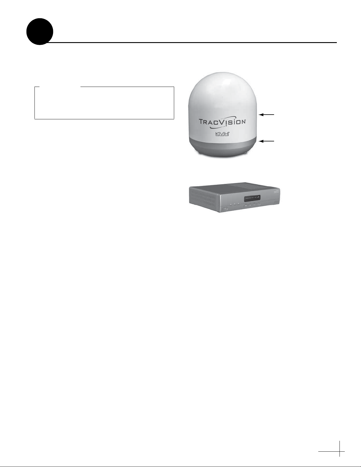
Always lift the antenna by the baseplate and
never by the radome or any portion of the
internal antenna assembly (see Figure 1).
IMPORTANT!
Radome
Baseplate
Antenna
Figure 1: TracVision M3/M2 System Components
1
Before you begin, follow these steps to make sure
you have everything you need to complete the
installation.
a. Unpack the box and ensure it contains
everything shown on the Kitpack Contents
List. Save the packaging for future use.
b. Carefully examine all of the supplied parts to
ensure nothing was damaged in shipment.
c. Gather all of the tools and materials listed
below. You will need these items to complete
the installation.
Inspect Parts and Get Tools
Interface Box/Controller
• #2 Phillips screwdriver
• 7/16" open-end wrench
• 7/16" socket wrench
• 1/2" socket or open-end wrench
• Electric drill and 5/16" (8 mm) bit
• Hole saw of desired diameter (for cable
access hole, see page 5)
• Silicone sealant or equivalent
•Adhesive tape
• Light hammer
• Center punch
• Eight 1/4" fasteners (see “Mount the
Interface Box” on page 11)
• Satellite TV receiver
3
Page 4
Antenna
Vessel Platform
Radar
Blocked!
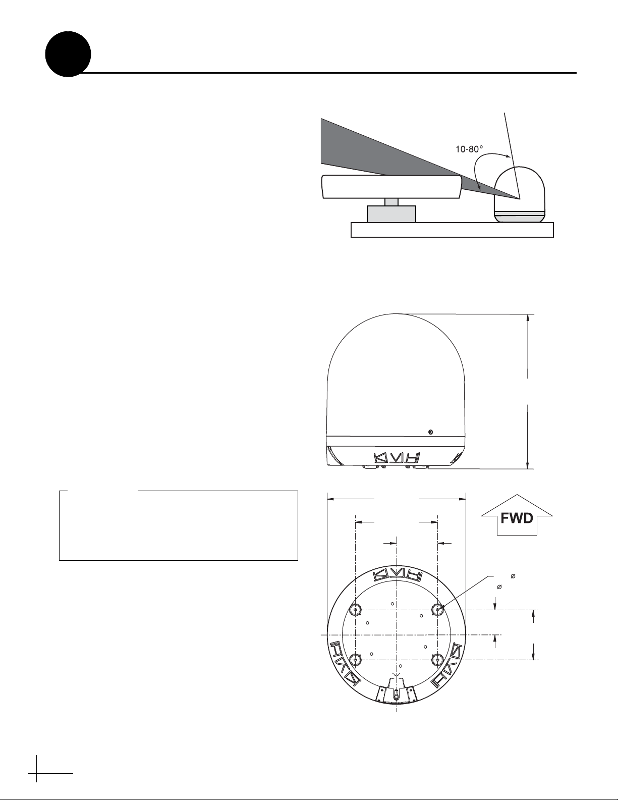
Figure 2: Blockage from Obstruction
Figure 3: Antenna Dimensions
Do not shorten or extend the antenna cable.
Since the cable carries data, power, and
communications, the integrity of this cable
and its connections is very important.
IMPORTANT!
2
Before you begin, consider the following
installation guidelines:
• Minimize blockage. The antenna requires a
clear view of the sky to receive satellite TV
(see Figure 2). The fewer obstructions, the
better the system will perform.
• Make sure the mounting surface is wide
enough to accommodate the antenna’s base
(see Figure 3). Also make sure it is flat, level
(within ±2°), strong enough to support the
antenna’s weight (18 lbs/8.2 kg), and rigid
enough to withstand vibration.
• Custom mounting solutions, including struts
and masts, are available from several thirdparty manufacturers. Contact your local KVH
dealer or distributor for details.
• KVH recommends that you do not mount the
antenna on the same level as the radar,
because the radar’s energy might overload
the antenna.
• Be sure to mount the antenna near enough to
the supplied interface box belowdecks to
allow you to connect the 50-ft. (15 m) coaxial
cable between the antenna and the interface
box, while still maintaining sufficient slack in
the cable.
Plan the Installation
17.3"
(44 cm)
• When choosing a location for the interface
box and receiver, find a dry, well-ventilated
area belowdecks away from any heat sources
or salt spray. Also be sure the interface box
front panel will be easily accessible to the
4
user.
15.5"
(39.4 cm)
9.2"
(23.4 cm)
4.6"
(11.7 cm)
Cable Connector
4 x 0.3"
( 0.8 cm)
2.8"
(7.1 cm)
5.6"
(14.2 cm)
Page 5
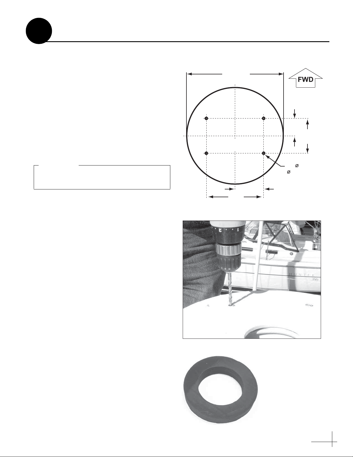
X
15.5"
(39.4 cm)
2.8"
(7.1 cm)
5.6"
(14.2 cm)
4.6" (11.7 cm)
9.2"
(23.4 cm)
4 x 0.31"
( 0.8 cm)
Mounting Holes
Cable Access Hole
(Suggested)
Antenna Base
Figure 4: Antenna Mounting Holes Layout
Be sure the mounting surface is flat and level.
Use a separate mounting plate, if necessary.
IMPORTANT!
Figure 5: Drilling Antenna Mounting Holes
Center
Between
Mounting
Holes
Figure 6: Foam Seal
3
Once you have identified a suitable antenna
mounting site, according to the guidelines
provided on page 4, follow these steps to prepare
the mounting site for installation.
a. Unfold the antenna mounting template
(supplied in the Customer Welcome Kit) and
place it onto the mounting surface. Make sure
the “FWD” (forward) arrow points toward
the bow and is parallel to the vessel’s
centerline (see Figure 4). You don’t need to
mount the antenna exactly on the centerline (the
closer, the better), but the antenna’s forward
arrow must be parallel to it.
b. Using the template, mark the locations for the
four mounting holes.
Prepare the Mounting Site
c. Drill a 5/16" (8 mm) hole at the four
mounting hole locations you marked in
Step b (see Figure 5). Later, you will insert
four 1/4"-20 bolts through these holes to
secure the antenna to the mounting surface.
d. Mark a location for the cable access hole,
either in the center of the antenna mounting
hole pattern or in an area aft of the antenna.
Later, you will route the antenna cable
through this hole and into the vessel.
e. Using a hole saw, drill the cable access hole in
the location you marked in Step d. Be sure to
size the hole appropriately to maintain a
cable bend radius of at least 3" (75 mm). If the
hole location is in the center of the antenna
mounting hole pattern, the diameter of the
cable access hole must not exceed 3.5"
(88 mm). Smooth the edges of the hole to
protect the cable.
f. Clean and dry the antenna mounting surface.
g. Peel off the paper backing from the supplied
foam seal to expose the adhesive. Then press
the foam seal down firmly onto the mounting
surface, centered between the antenna
mounting holes (see Figure 6).
5
Page 6
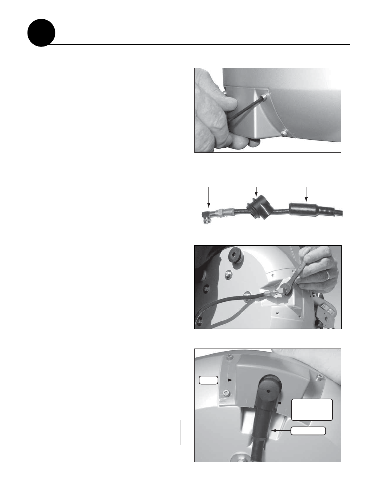
Figure 7: Removing the Connector Cover
Right-Angle
Connector Extension Rubber Boot
Figure 8: Rubber Boot Extension for Right-Angle Connector
Figure 9: Connecting the Antenna Cable
Right-Angle
Boot Extension
(if necessary)
Rubber Boot
Cover
Figure 10: Protecting the Cable Connection
Be sure to seal the cable access hole to prevent
water from leaking into the vessel.
IMPORTANT!
4
Follow these steps to connect the antenna cable to
the antenna.
a. Using the supplied 3 mm Allen hex key,
remove the connector cover from the
antenna’s base (see Figure 7). Save the cover
and the four M4 cap screws for later use.
b. Route the antenna cable belowdecks through
the cable access hole. Be sure to keep the end
of the cable with the rubber sealing boot at
the antenna site.
c. If you are routing the cable underneath the
antenna, attach the right-angle connector to
the antenna end of the cable. Hand-tighten,
then tighten with a 7/16" wrench for 1/4 turn
to ensure an electrical and weather-proof
connection. Then place the supplied rightangle rubber boot extension onto the end of
the cable (see Figure 8).
Wire the Antenna
d. Connect the cable to the antenna. Hand-
tighten, then tighten with a 7/16" wrench for
1/4 turn (see Figure 9).
e. If you are using a right-angle connector, slide
the right-angle rubber boot extension up the
cable until it covers the right-angle connector.
f. Slide the rubber boot up the cable un ti l it
covers the connector. If you are using a rightangle connector, be sure the boot mates with
the extension (see Figure 10). This boot will
help protect the connector from the elements.
g. Reattach the cover over the connector, as
shown in Figure 10. Secure in place with the
M4 cap screws you removed in Step a. The
cover must be attached before you mount the
antenna.
h. Leave an adequate service loop,
approximately 8" (20 cm) of slack, in the
antenna cable for easy serviceability.
i. Weatherproof and seal the cable access hole
as required.
6
Page 7

Figure 11: Removing the Radome
Figure 12: Removing the Shipping Restraint
Washer
Bolt
Spacer
Figure 13: Shipping Restraint Hardware
5
Follow these steps to remove the shipping
restraint, which prevents the internal antenna
assembly from moving during shipment. The
antenna will not work with this restraint still in
place.
a. Remove the three #10-32 screws securing the
radome to the antenna.
b. Carefully lift the radome straight up until
clear of the antenna assembly and set it aside
in a safe place (see Figure 11).
NOTE: Due to the snug fit, some contact between the
radome’s sealing gasket and the antenna mechanism is
normal.
c. Using a 7/16" socket wrench, remove the
shipping restraint bolt, washer, and spacer
securing the antenna assembly to the base
(see Figure 12 and Figure 13). Save the
restraint for future use.
Remove the Shipping Restraint
d. Position the antenna onto the mounting
surface. The antenna’s base should rest
squarely atop the foam seal.
7
Page 8

Figure 14: “Forward” Arrow
Be sure to insert the mounting bolts from
above and use the supplied hardware for a
secure installation.
IMPORTANT!
Figure 15: Tightening the Mounting Bolts from Above
1/4"-20 x 3" Bolt
1/4" Flat Washer
(5/8" diameter)
Antenna Base
Foam Seal
Mounting Surface
1/4" Flat Washer
(1" diameter)
1/4"-20 Lock Nut
Figure 16: Mounting Hardware
6
Follow these steps to mount the antenna to the
mounting surface.
a. Align the four holes in the antenna’s
baseplate with the four holes in the mounting
surface. Ensure the “Forward” arrow inside
the baseplate points toward the bow and is
parallel to the vessel’s centerline (see
Figure 14).
b. Secure the antenna’s baseplate to the
mounting surface using four 1/4"-20 bolts,
5/8" washers, 1" washers, and lock nuts, as
shown in Figure 15 and Figure 16.
Mount the Antenna
c. Tighten the bolts until the foam seal is
compressed and the antenna’s four rubber
feet are bottomed against the mounting
surface.
d. Reinstall the antenna’s radome to protect the
antenna while you’re working belowdecks.
While pressing the radome down onto the
base, secure the radome to the base using the
three #10-32 screws you removed earlier.
Later, you will remove the radome again to
set the LNB skew angle.
8
Page 9

Do not shorten or extend the antenna cable.
Since the cable carries data, power, and
communications, the integrity of this cable
and its connections is very important.
IMPORTANT!
Be sure to route cables within the vessel
appropriately to avoid damage. For example,
do not route any cables through wet areas
(bilges) or near hot exhaust pipes. Also be
sure you do not kink the cable; maintain a
bend radius of at least 3" (75 mm).
IMPORTANT!
Figure 17: Wiring the Interface Box
7
Follow these steps to connect the antenna cable
and receiver to the interface box.
a. Connect the antenna cable (A) to the “To
KVH Antenna” jack on the interface box (see
Figure 17).
Wire the Interface Box
Antenna
(A)
Deck
Interface Box
Primary
Receiver
To KVH Antenna
(B)
Satellite TV Receiver
Satellite In
b. Connect an RF coaxial cable (B) from the
“Primary Receiver” jack on the interface box
to the “Satellite In” jack on the receiver.
c. Connect the receiver to the customer’s
television. Follow the instructions in the
receiver’s manual.
9
Page 10

CAUTION
For your own safety, disconnect vessel
power and make sure the circuit is dead
before you connect any power wires.
Figure 18: Interface Box Power Wiring
8
The interface box requires 10-16 VDC power
input supporting 50 watts (4.2 amps @ 12 VDC).
Follow these steps to connect power to the
interface box.
a. Before you connect the power wires, turn off
vessel power and test the circuit to ensure no
power is present.
b. Connect the individual power wires to a
dedicated 10-amp or 15-amp circuit breaker.
Connect the negative (black) wire to ground
(power return), and connect the positive (red)
wire to +12 VDC vessel power.
Connect Power
Powe r
Black
Red
Ferrite
Coil
Ground
Input Power
(10-16 VDC)
NOTE: As an alternative, you may use an AC/DC
power supply (KVH part #72-0206-01) to supply
power to the interface box.
c. Plug the other end of the wires into the
“Power” jack on the rear panel of the
interface box (see Figure 18).
NOTE: Do not remove the small ferrite coil that is
clamped onto the power wires. This coil suppresses
EMI (electromagnetic interference) from the interface
box.
d. Connect power to the receiver. Follow the
instructions in the receiver’s manual.
10
Page 11

Figure 19: Interface Box Mounting
To avoid overheating, do not block the upper
vents of the interface box.
IMPORTANT!
9
Once all cables are connected, follow these steps
to install the interface box inside the vessel.
a. Attach the two mounting brackets to the
sides of the unit using three #2-56 screws.
Simply screw these fasteners into the vent
slots (see Figure 19).
Mount the Interface Box
1⁄4" Fasteners (x4)
(not supplied)
#2-56 x 1⁄4"
Screws (x3)
b. Secure the brackets to the mounting surface
using appropriate 1/4" fasteners (not
supplied).
NOTE: Be sure to leave enough slack in the
connecting cables (service loop) for easy serviceability.
Bracket
11
Page 12

Figure 20: Interface Box Power Switch and Status Lights
ASTRA1
SYSTEM NEEDS SETUP
Figure 21: “System Needs Setup” Screen
Figure 22: Interface Box Buttons
10
Follow these steps to turn on the system for the
first time.
a. Ensure the antenna has a clear, unobstructed
view of the sky.
b. Apply power to the TV and the receiver.
c. Press the power switch on the front of the
interface box to apply power to the
TracVision system (see Figure 20).
d. Wait one minute for system startup.
e. Verify that the VOLTAGE and RECEIVER
status lights on the interface box are lit green.
Verify that the ANTENNA status light is
either lit green or flashing green (see
Figure 20). If not, refer to the User’s Guide for
troubleshooting information.
f. Verify that the “System Needs Setup” screen
is displayed on the interface box (see
Figure 21).
Turn On the System
Power Switch
Status Lights
g. Using the buttons on the interface box front
panel (see Figure 22), follow the steps in the
next sections to set up the TracVision system
for the customer’s location and desired
satellites.
12
Page 13

Figure 23: Latitude/Longitude Setting
#
1
2
3
4
5
6
7
8
9
10
11
12
7° W
7° E
22° E
45° E
7° W
7° E
22° E
7° W
7° E
22° E
40° E
7° W
67° N
67° N
67° N
65° N
63° N
63° N
63° N
57° N
57° N
57° N
55° N
53° N
LAT
LONG
#
13
14
15
16
17
18
19
20
21
22
23
24
7° E
22° E
7° W
7° E
7° W
7° E
22° E
37° E
7° W
7° E
22° E
37° E
53° N
50° N
47° N
47° N
43° N
43° N
43° N
43° N
36° N
36° N
36° N
36° N
LAT
LONG
1
2
3
4
11
7
6
5
8
9
10
12
13
14
16
15
17
18
19
20
21 22 23 24
Figure 24: Latitude/Longitude Data for Europe
11
Enter Your Latitude & Longitude
Follow these steps and refer to the flowchart in
Figure 23 to enter your vessel’s latitude and
longitude into the system. The antenna will use
this position information to calculate the proper
LNB skew setting for your position and speed up
satellite acquisition.
If you are located in Europe and don’t know your
latitude and longitude, you can use the
approximate latitude/longitude for your region
shown in Figure 24. For example, if you are
located in Antibes, France (region #18), you
would enter 43° N latitude and 7° E longitude.
a. Press any button on the interface box front
panel.
ASTRA1
SYSTEM NEEDS SETUP
LAT/LONG= 41N, 071W?
CHANGE ACCEPT
LAT/LONG= 41N, 071W
CHANGE ACCEPT
LAT/LONG= 55N, 012E?
CHANGE ACCEPT
Press any button
to begin.
Press CHANGE to set
each digit plus N/S
(north or south) and
E/W (east or west).
Press ACCEPT to
save each digit.
b. At “Lat/Long= 41N, 071W?,” press
CHANGE. A cursor appears under the first
number in the displayed latitude.
c. Press CHANGE until the number is set to the
first digit of your vessel’s current latitude.
Then press ACCEPT. The cursor moves to the
next number.
d. Repeat Step c to set the remaining digits (plus
North/South and East/West directions) of
your latitude and longitude. Once you have
e. Press ACCEPT to confirm your selection.
set the entire position, the cursor disappears
from the display.
Continued on the next page.
13
Page 14

Figure 25: Satellite Selection
12
Follow these steps and refer to the flowchart in
Figure 25 to set up the antenna for the customer’s
desired satellites. You may choose up to four
satellites from the following list:
•Arabsat, 26°E
• Astra 1, 19.2° E
• Astra 2N, 28.2° E
Select Satellites
•Nilesat, 7°W
• Optus D1, 160° E
• Optus C1, 156° E
SAT 1= ARABSAT?
CHANGE ACCEPT
SAT 2= NONE?
CHANGE ACCEPT
Press CHANGE until
the desired primary
satellite is displayed.
Then press ACCEPT.
Choose up to 3
additional satellites.
Choose NONE when
you are finished.
• Astra 2S, 28.2° E
•Eutelsat W3A, 7°E
• Hispasat, 30° E
•Hotbird, 13°E
•Hotbird WB, 13°E
NOTE: If the desired satellite is not listed above, you
can set up a special user-defined satellite. Refer to the
User’s Guide for details.
a. At “Sat 1= Arabsat?,” press CHANGE until
the display shows the first (primary) satellite
you wish to set up in the antenna. Then press
ACCEPT.
NOTE: The display might show additional satellites
not listed above. However, the TracVision system
supports only those satellites specified above.
b. Repeat Step a to choose the remaining
desired satellites. If you don’t need to set up
four satellites, choose NONE instead.
c. Pay close attention to the interface box
display while the antenna restarts. The
display will show the recommended LNB
skew angle for your selected satellite(s) and
position. You will need this skew angle to
complete the next step.
• Pas 9, 58° W
• Sirius, 5° E
• Thor, 0.8° W
• Turksat 1C, 42° E
SAT 3= NONE?
CHANGE ACCEPT
SAT 4= NONE?
CHANGE ACCEPT
CONFIGURING ANTENNA
RESTARTING ANTENNA
Software versions are displayed
INSTALLED SATELLITES
HOTBIRD, THOR
LAT/LONG: 55N, 012E
HOTBIRD SKEW:-12.5
CHECK LNB SETTING
OR
AVERAGE SKEW:-12.3
CHECK LNB SETTING
Yo ur chosen satellites
are displayed.
Yo ur latitude & longitude
are displayed.
The recommended skew
angle is displayed.
If you chose multiple
satellites, the average
skew is displayed.
d. Set up your satellite TV receiver for the same
satellites you set up in the antenna. Refer to
your receiver’s manual for details. Be sure to
set them up in the same order. For example,
set up SAT 1 (or A) in the receiver to the same
satellite as SAT 1 in the antenna, and set up
SAT 2 (or B) in the receiver to the same
satellite as SAT 2 in the antenna.
14
Page 15

CAUTION
Disconnect power from the antenna before
you remove the radome. The antenna has
moving parts that can cause injury.
Reflector
LNB
Figure 26: Location of LNB on Back of Antenna Reflector
Figure 27: LNB Skew Angle Adjustment
Make sure the LNB is fully inserted into the
choke feed. The shaft of the LNB must be
seated properly against the feed tube to
ensure optimum performance.
IMPORTANT!
Figure 28: Radome Labels Facing Fore and Aft
13
Set the LNB Skew Angle
Follow these steps to set the antenna’s LNB to the
skew angle you noted in the previous step.
a. Turn off and unplug your satellite TV
receiver.
b. Press the power switch on the front of the
interface box to disconnect power from the
TracVision system. Make sure the VOLTAGE
status light goes out.
c. Remove the three #10-32 screws securing the
radome to the antenna. Carefully remove the
radome and set it aside in a safe place.
d. Locate the LNB on the back of the antenna’s
reflector (see Figure 26).
e. Loosen the two wing screws securing the
LNB to the choke feed (see Figure 27).
f. Adjust the LNB, clockwise or counter-
clockwise, until the skew arrow on the LNB
points to the correct skew angle on the choke
feed.
g. Tighten the wing screws to secure the LNB in
place.
h. Reinstall the antenna’s radome. The radome’s
“TracVision” labels should face fore and aft
(see Figure 28). While pressing the radome
down onto the base, secure the radome to the
base using the three #10-32 screws you
removed earlier.
Choke Feed
Skew Arrow
Wing Screw
(1 of 2)
LNB
+
–
5
15
5
15
25
35
45
55
40
50
65
60
70
25
10
10
0
20
20
30
35
30
45
40
55
50
65
60
70
i. Install a protective plastic screw cap
(supplied in the kit) over each radome screw.
15
Page 16

CAUTION
In the unlikely event that you need to
remove the radome, remove power from the
antenna first because the antenna’s moving
parts can cause injury.
TraracVisionision
Blocked!
Figure 29: Blockage Example
14
Before you leave the vessel, test the system to
verify proper operation. Then give the Customer
Welcome Kit and all manuals to the customer
and explain how to use the system. Also be sure
the customer understands the follow ing:
• Keep the radome installed on the antenna at
all times. The radome protects the antenna’s
moving parts from wind, rain, and debris.
• The antenna must have a clear view of the
sky to receive satellite TV. Common causes of
blockage include trees, buildings, bridges,
and equipment on the vessel itself (see
Figure 29). Heavy rain or snow might also
temporarily interrupt reception.
Educate the Customer
• Clean the antenna regularly. Dirt buildup can
affect satellite TV reception.
• The antenna’s LNB must be set to the correct
skew angle for your location and selected
satellite(s) to optimize reception. Ther efore,
you might need to adjust the skew when you
travel to a different region or change your
setup. Refer to the User’s Guide for details.
• (TracVision M2 only) The TracVision M2 is
designed for use while at anchor only. It will
acquire and track the satellite while the vessel
is moored, either at dock or at anchor, but not
while underway.
• Please register the system with KVH. The
registration process is quick, easy, online, and
ensures the best possible service from KVH.
Visit www.kvh.com/register or refer to the
Product Registration Form for details.
• The vessel must be located within the
selected satellite’s coverage area. To view
satellite coverage maps, visit: www.kvh.com/
footprint.
• Refer to the User’s Guide for complete
16
operation and troubleshooting information.
Page 17

KVH Industries, Inc.
50 Enterprise Center Middletown, RI 02842-5279 U.S.A.
Phone: +1 401 847-3327 Fax: +1 401 849-0045
E-mail: info@kvh.com Internet: www.kvh.com
KVH Europe A/S
Kokkedal Industripark 2B 2980 Kokkedal Denmark
Phone: +45 45 160 180 Fax: +45 45 160 181
E-mail: info@kvh.dk Internet: www.kvh.com
© Copyright 2008 KVH Industries Inc. KVH, TracVision, and TracPhone are registered trademarks of KVH Industries Inc.
 Loading...