

Page 1
TracVision® M1DX
with Multi-service Interface Box/Controller
®
M1DX Installation Guide
TracVision
Page 2
TracVision M1DX Installation Guide
Multi-service Interface Box/Controller Configuration
These instructions explain how to install the TracVision M1DX satellite TV antenna system on a
vessel. Complete instructions on how to use the system are provided in the User’s Guide.
Installation Steps
1. Inspect Parts and Get Tools ...............3
2. Plan the Installation.............................4
3. Prepare the Mounting Site .................5
4. Wire the Antenna ................................6
5. Remove the Shipping Restraint.........7
6. Mount the Antenna.............................8
7. Wire the Interface Box.........................9
8. Connect Power...................................10
9. Mount the Interface Box...................11
10. Turn On the System...........................12
11. Set Up the System..............................13
12. Enter Your Latitude & Longitude...15
13. Run Check Switch Tests....................16
14. Educate the Customer.......................18
Who Should Install the System?
To ensure a safe and effective installation, KVH recommends that a KVH-authorized marine
technician install the TracVision M1DX antenna. To find a technician near you, please visit
www.kvh.com/wheretogetservice.
Related Documentation
The following additional documents are provided with the TracVision M1DX system:
Document
User’s Guide Operation, setup, and troubleshooting information
Product Registration Form Details on registering the product with KVH
Warranty Statement Warranty terms and conditions
Contents List List of every part supplied in the kit
Description
Technical Support
If you need technical assistance, please contact KVH Technical Support:
Phone: +1 401 847-3327
E-mail: techs@kvh.com
(Mon.-Fri., 9 am-6 pm ET; Sat. 9 am-2 pm ET)
KVH, TracVision, and the unique light-colored dome with dark contrasting baseplate are registered trademarks of KVH Industries, Inc.
All other trademarks are property of their respective companies. The information in this document is subject to change without notice.
No company shall be liable for errors contained herein. © 2008-2011 KVH Industries, Inc., All rights reserved. 54-0579 Rev. C
1
Page 3
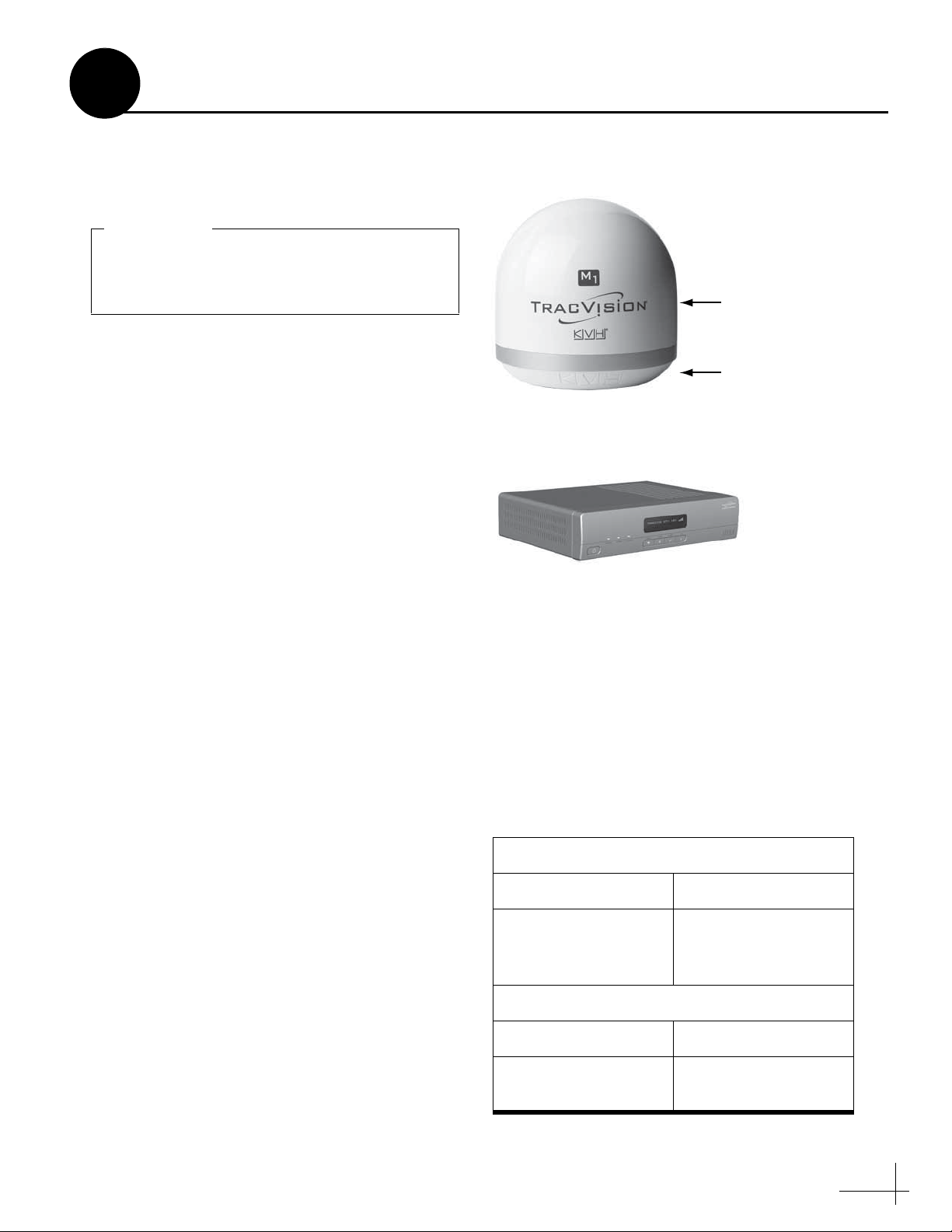
Always lift the antenna by the baseplate and
never by the radome or any portion of the
internal antenna assembly (see Figure 1).
IMPORTANT!
Figure 1: TracVision M1DX System Components
Figure 2: KVH-Validated Receivers
Standard-Definition Models
DIRECTV DISH Network
D12
D11
D10
311
211k
211
High-Definition (HD) Models
DIRECTV DISH Network
HD not supported 211k
211
1
Before you begin, follow these steps to make sure
you have everything you need to complete the
installation.
NOTE: Henceforward, this manual uses the term
“interface box” to refer to the multi-service interface
box/controller.
a. Unpack the box and ensure it contains
everything shown on the Kitpack Contents
List. Save the packaging for future use.
b. Carefully examine all of the supplied parts to
ensure nothing was damaged in shipment.
Inspect Parts and Get Tools
Antenna
Radome
Baseplate
Multi-service Interface Box/Controller
c. Gather all of the tools and materials listed
below. You will need these items to complete
the installation.
• #2 Phillips screwdriver
• 7/16" open-end wrench
• 3/8" socket or open-end wrench
• Electric drill and 1/4" (6 mm) bit
• Hole saw of desired diameter (for cable
access hole, see page 5)
• Silicone sealant or equivalent
•Adhesive tape
• Light hammer
• Center punch
• Eight 1/4" fasteners (see “Mount the
Interface Box” on page 11)
• Satellite TV receiver(s) for your desired
service (see Figure 2 for a list of validated
receivers; for information on connecting
different receiver models, contact KVH
Technical Support at 401-847-3327)
3
Page 4
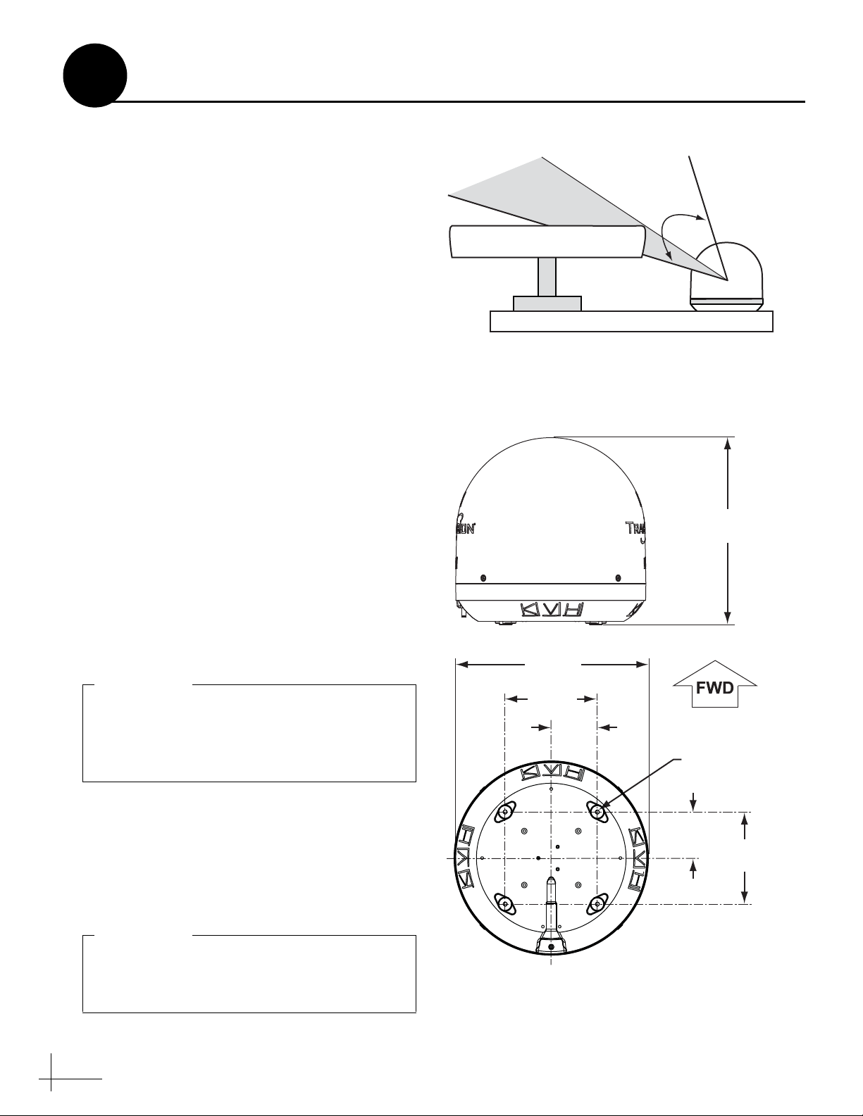
Antenna
Blocked!
17-73°
Vessel Platform
Radar
Figure 3: Blockage from Obstruction
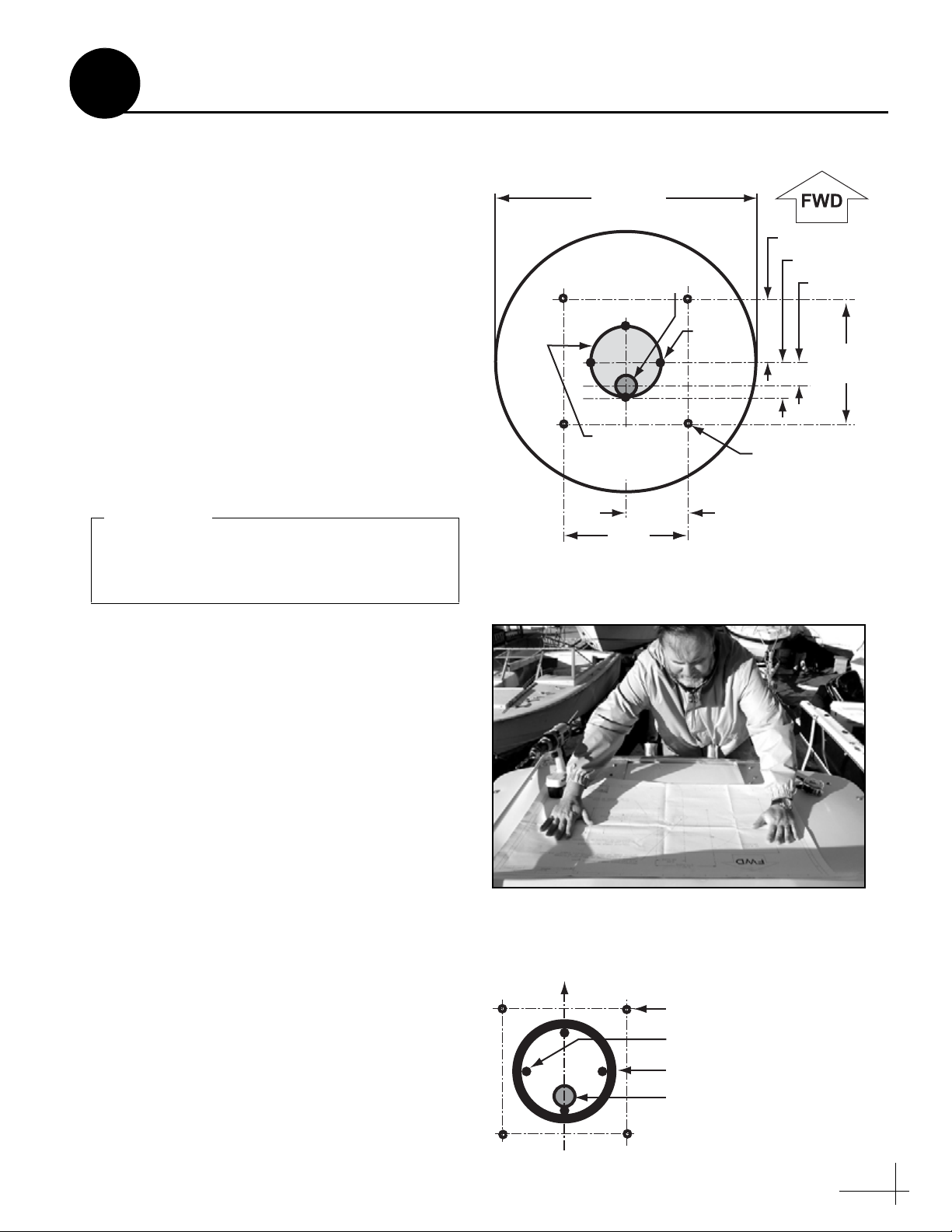
4 x Ø0.28"
(Ø7.04 cm)
Ø13.5"
(Ø34.3 cm)
6.4"
(16.3 cm)
3.2"
(8.1 cm)
3.2"
(8.1 cm)
6.4"
(16.3 cm)
Cable Connector
13.13"
(33.4 cm)
Figure 4: Antenna Dimensions
Do not shorten or extend the antenna cable.
Since the cable carries data, power, and
communications, the integrity of this cable
and its connections is very important.
IMPORTANT!
Be sure to follow the guidelines above.
Damage caused by an improper installation is
not covered under KVH warranty.
IMPORTANT!
2
Before you begin, consider the following
installation guidelines:
• Minimize blockage. The antenna requires a
clear view of the sky to receive satellite TV
(see Figure 3). The fewer obstructions, the
better the system will perform.
• Make sure the mounting surface is wide
enough to accommodate the antenna’s base
(see Figure 4). Also make sure it is flat, level
(within ±2°), strong enough to support the
antenna’s weight (7.5 lbs), and rigid enough
to withstand vibration.
• Custom mounting solutions, including struts
and masts, are available from several thirdparty manufacturers. Contact your local KVH
dealer or distributor for details.
• KVH recommends that you do not mount the
antenna on the same level as the radar,
because the radar’s energy might overload
the antenna.
• Be sure to mount the antenna near enough to
the supplied interface box belowdecks to
allow you to connect the 50-ft. (15 m) coaxial
cable between the antenna and the interface
box, while still maintaining sufficient slack in
the cable.
Plan the Installation
• When choosing a location for the interface
box and receiver(s), find a dry, wellventilated area belowdecks away from any
heat sources or salt spray. Also be sure the
interface box front panel will be easily
4
accessible to the user.
Page 5
13.5"
(34.3 cm)
3.2" (8.1 cm)
6.4"
(16.3 cm)
3.2" (8.1 cm)
6.4"
(16.3 cm)
4 x Ø0.25"
(Ø0.6 cm)
Mounting Holes
Antenna Base
1.75" (4.4 cm)
1.25" (3.2 cm)
Maximum
Cable Access Hole
Ø3.5" (Ø8.9 cm)
Recommended
Cable Access Hole
Ø1.0" (Ø2.5 cm)
4 x Seal
Guides
Figure 5: Antenna Mounting Holes Layout
Figure 6: Using the Template to Mark Hole Locations
The diameter of the cable access hole must not
exceed 3.5" (89 mm) to maintain the integrity
of the foam seal.
IMPORTANT!
Figure 7: Foam Seal
3
Prepare the Mounting Site
Once you have identified a suitable antenna
mounting site, according to the guidelines
provided on page 4, follow these steps to prepare
the mounting site for installation.
a. Unfold the antenna mounting template
(supplied in the Customer Welcome Kit) and
place it onto the mounting surface. Make sure
the “FWD” (forward) arrow points toward
the bow and is parallel to the vessel’s
centerline (see Figure 5 and Figure 6). You
don’t need to mount the antenna exactly on the
centerline (the closer, the better), but the
antenna’s forward arrow must be parallel to it.
b. Mark the locations for the four mounting
holes on the mounting surface in the
locations indicated on the template.
c. Mark a location for the cable access hole.
KVH recommends a location 1.25" (32 mm)
aft of the center of the mounting hole pattern,
as shown on the template (see Figure 5). Size
the hole appropriately to maintain a cable
bend radius of at least 3" (75 mm).
d. Mark four seal guides in the locations
indicated on the template. Later, these guides
will help you position the foam seal correctly.
e. Drill a 1/4" (6 mm) hole at the four mounting
hole locations you marked in Step b. Later,
you will insert four #10-32 screws through
these holes to secure the antenna to the
mounting surface.
f. Using a hole saw, drill the cable access hole in
the location you marked in Step c. Smooth the
edges of the hole to protect the cable. Later,
you will route the antenna cable through this
hole and into the vessel.
g. Clean and dry the antenna mounting surface.
Bow
Mounting Holes (x4)
Guides (x4)
Foam Seal
h. Peel off the paper backing from the supplied
foam seal to expose the adhesive. Then press
the foam seal down firmly onto the mounting
surface, surrounding the guides and centered
between the mounting holes (see Figure 7).
Cable Access Hole
5
Page 6
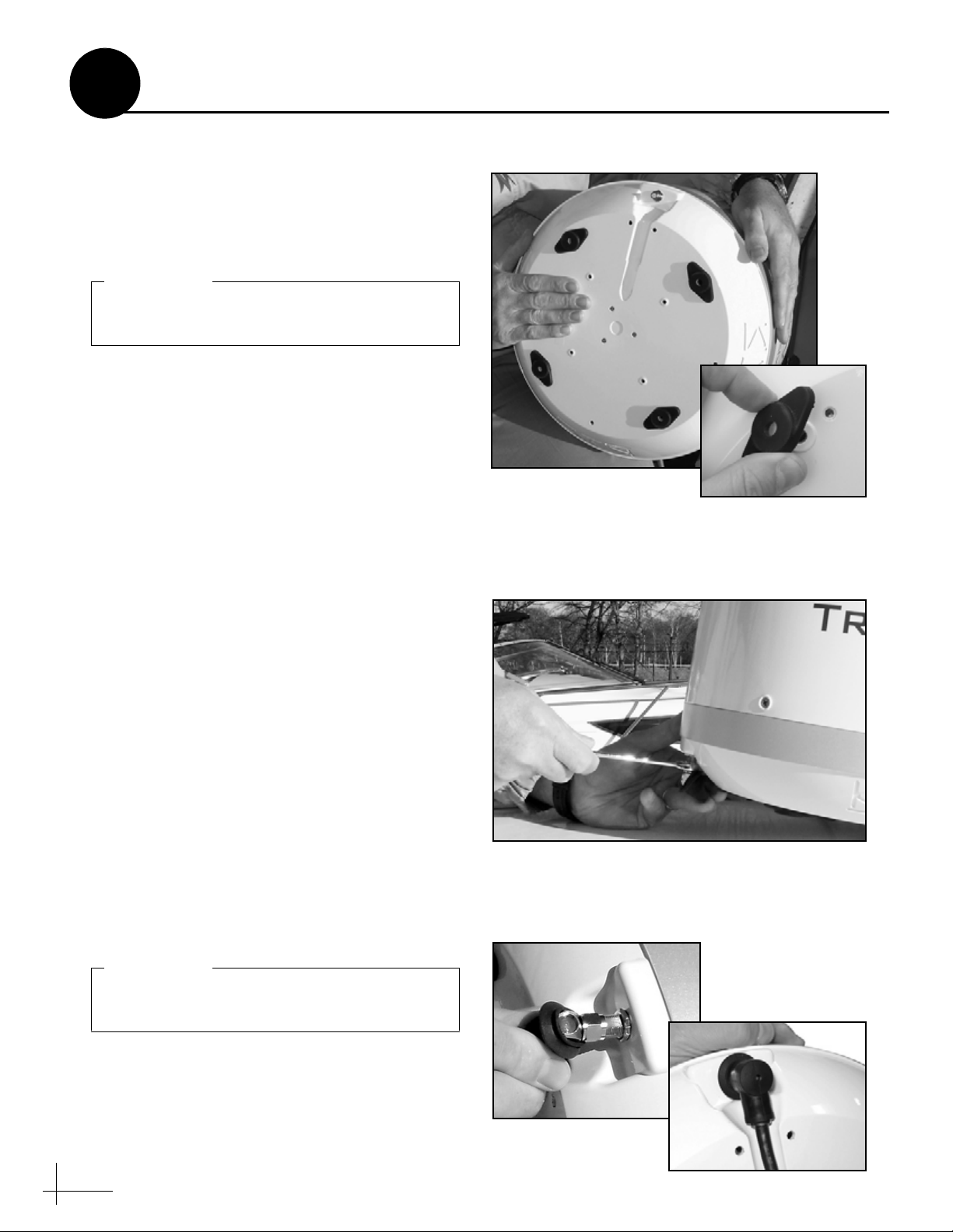
Figure 8: Attaching the Rubber Feet
Be sure to install the rubber feet. They are
required to isolate the antenna from vibration.
IMPORTANT!
Figure 9: Connecting the Antenna Cable
Figure 10: Protecting the Connector with the Rubber Boot
Be sure to seal the cable access hole to prevent
water from leaking into the vessel.
IMPORTANT!
4
Follow these steps to connect the antenna cable to
the antenna.
a. First attach the four rubber mounting feet
(supplied in the kitpack) to the bottom of the
antenna at the locations shown in Figure 8.
b. Route the antenna cable belowdecks through
the cable access hole.
If you are routing the cable underneath the
antenna (normal installation):
Keep the end of the cable with the right-angle
connector and rubber sealing boot at the
antenna site. You may remove the straight
rubber boot at the opposite end of the cable
for easier cable routing, if necessary.
Wire the Antenna
If you are routing the cable straight down
from the connector (alternate installation):
Keep the straight connector and rubber
sealing boot at the antenna site.
c. Connect the cable to the antenna. Hand-
tighten, then tighten with a 7/16" wrench for
1/4 turn to ensure an electrical and weatherproof connection (see Figure 9).
d. Position the rubber boot over the connector to
help protect the connector from the elements
(see Figure 10).
e. Leave an adequate service loop,
approximately 8" (20 cm) of slack, in the
antenna cable for easy serviceability.
f. Weatherproof and seal the cable access hole
as required.
6
Page 7

Figure 11: Removing the Radome Screws
Figure 12: Removing the Radome
Figure 13: Removing the Shipping Restraint
5
Follow these steps to remove the shipping
restraint, which prevents the internal antenna
assembly from moving during shipment.
a. Remove the four #8-32 screws securing the
radome to the antenna (see Figure 11).
b. Carefully lift the radome straight up until
clear of the antenna assembly and set it aside
in a safe place (see Figure 12).
c. Using cutting pliers, cut and remove the tie-
wrap securing the antenna assembly to the
baseplate (see Figure 13).
d. Position the antenna onto the mounting
surface. The antenna’s base should rest
squarely atop the foam seal.
Remove the Shipping Restraint
7
Page 8

FORWARD
Figure 14: Aligning the “Forward” Arrows
Be sure to insert the mounting bolts from
above and use the supplied hardware for a
secure installation.
IMPORTANT!
Figure 15: Tightening the Mounting Bolts from Above
#10-32 x 3" Screw
#10 Flat Washer
(0.43" diameter)
Antenna Base
Foam Seal
Mounting Surface
#10 Flat Washer
(0.75" diameter)
#10 Lock Nut
Rubber Foot
Figure 16: Mounting Hardware
Use only manual hand tools to tighten the
mounting screws. The torque from a power
tool might distort the antenna baseplate.
IMPORTANT!
6
Follow these steps to mount the antenna to the
mounting surface.
a. Place the antenna baseplate over the holes
drilled in the mounting surface. Ensure the
“Forward” arrows inside the baseplate point
toward the bow and are parallel to the
vessel’s centerline (see Figure 14).
b. Secure the antenna’s baseplate to the
mounting surface using four #10-32 Phillips
screws, 0.43" flat washers, 0.75" flat washers,
and lock nuts, as shown in Figure 15 and
Figure 16.
Mount the Antenna
c. Using hand tools, tighten the bolts until the
foam seal is compressed and the antenna’s
four rubber feet are bottomed against the
mounting surface.
d. Reinstall the radome onto the antenna. The
radome’s “TracVision” labels should face
fore and aft. Secure the radome to the base
using the four #8-32 screws you removed
earlier.
8
Page 9
Do not shorten or extend the antenna cable.
Since the cable carries data, power, and
communications, the integrity of this cable
and its connections is very important.
IMPORTANT!
Be sure to route cables within the vessel
appropriately to avoid damage. For example,
do not route any cables through wet areas
(bilges) or near hot exhaust pipes. Also be
sure you do not kink the cable; maintain a
bend radius of at least 3" (75 mm).
IMPORTANT!
(A)
(B)
Satellite In
To KVH Antenna
Unstacked
Output
Deck
Interface Box
Primary Satellite TV Receiver
Antenna
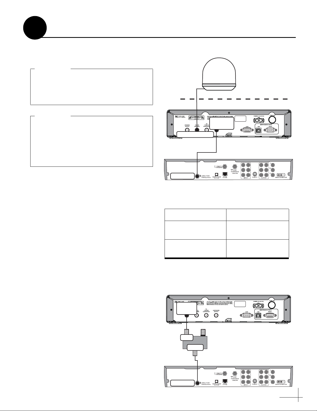
Figure 17: Wiring the Interface Box
Figure 18: Destacker Models to Connect Additional Receiver(s)
# of Addl. Receivers Destacker Model
1Single-output
(KVH part #19-0347)
2Dual-output
(KVH part #19-0410)
Satellite In
Stacked
Output
Interface Box
Additional Satellite TV Receiver
INPUT To TV
OUTPUT / To RECEIVER
Destacker
Purchased Separately
(See table for model required)
Input
Output
Figure 19: Connecting an Additional Receiver
7
Wire the Interface Box
Follow these steps to connect the antenna cable
and receiver(s) to the interface box.
a. Connect the antenna cable (A) to the “To
KVH Antenna” jack on the interface box (see
Figure 17).
b. Connect an RF coaxial cable (B) from the
“Unstacked Output” jack on the interface box
to the “Satellite In” jack on the receiver. This
receiver will control satellite selection.
c. Connect the receiver to the customer’s
television. Follow the instructions in the
receiver’s manual.
d. If you need to connect an additional receiver,
connect the receiver to the “Stacked Output”
jack on the interface box through an in-line
destacker (see Figure 18 and Figure 19).
The destacker converts the stacked signal from the
interface box into an unstacked signal, which
receivers are configured to decode.
9
Page 10

CAUTION
For your own safety, disconnect vessel
power and make sure the circuit is dead
before you connect any power wires.
Figure 20: Interface Box Power Wiring
8
The interface box requires 10-16 VDC power
input supporting 50 watts (4.2 amps @ 12 VDC).
Follow these steps to connect power to the
interface box.
a. Before you connect the power wires, turn off
vessel power and test the circuit to ensure no
power is present.
b. Connect the individual power wires to a
dedicated 10-amp or 15-amp circuit breaker.
Connect the negative (black) wire to ground
(power return), and connect the positive (red)
wire to +12 VDC vessel power.
Connect Power
Powe r
Black
Red
Ferrite
Coil
Ground
Input Power
(10-16 VDC)
NOTE: As an alternative, you may use an AC/DC
power supply (KVH part #72-0206-01) to supply
power to the interface box.
c. Plug the other end of the wires into the
“Power” jack on the rear panel of the
interface box (see Figure 20).
NOTE: Do not remove the small ferrite coil that is
clamped onto the power wires. This coil suppresses
EMI (electromagnetic interference) from the interface
box.
d. Connect power to the receiver(s). Follow the
instructions in the receiver’s manual.
10
Page 11

Figure 21: Interface Box Mounting
To avoid overheating, do not block the upper
vents of the interface box.
IMPORTANT!
9
Once all cables are connected, follow these steps
to install the interface box inside the vessel.
a. Attach the two mounting brackets to the
sides of the unit using three #2-56 screws.
Simply screw these fasteners into the vent
slots (see Figure 21).
Mount the Interface Box
1⁄4" Fasteners (x4)
(not supplied)
#2-56 x 1⁄4"
Screws (x3)
b. Secure the brackets to the mounting surface
using appropriate 1/4" fasteners (not
supplied).
NOTE: Be sure to leave enough slack in the
connecting cables (service loop) for easy serviceability.
Bracket
11
Page 12
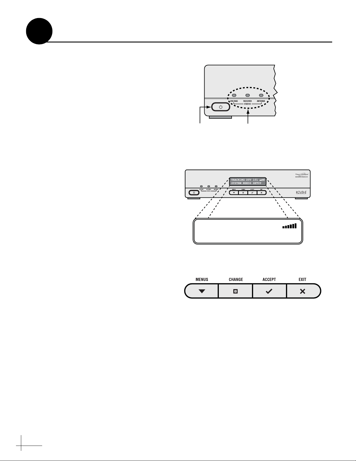
Figure 22: Interface Box Power Switch and Status Lights
Figure 23: “System Needs Setup” Screen
Figure 24: Interface Box Buttons
10
Follow these steps to turn on the system for the
first time.
a. Ensure the antenna has a clear, unobstructed
view of the sky.
b. Apply power to the TV and receiver.
c. Press the power switch on the front of the
interface box to apply power to the
TracVision system (see Figure 22).
d. Wait while the antenna searches the sky for
the satellite. Within a few minutes, all three
status lights on the front of the interface box
should be lit green (see Figure 22).
NOTE: If all three status lights are not lit green, refer
to the User’s Guide for troubleshooting information.
e. Verify that the “System Needs Setup” screen
is displayed on the interface box (see
Figure 23).
Turn On the System
Power Switch
Status Lights
f. Using the buttons on the interface box front
panel (see Figure 24), follow the steps in the
next section to set up the TracVision system
for the customer’s service provider:
Option 1 - DISH Network (see page 13)
Option 2 - DIRECTV (see page 14)
NOTE: If you do not see an operating mode on the
following pages that tracks your desired set of
satellites, you can select up to five satellites in Manual
mode instead. Refer to the User’s Guide for details.
TRACKING DTV 101
SYSTEM NEEDS SETUP
12
Page 13
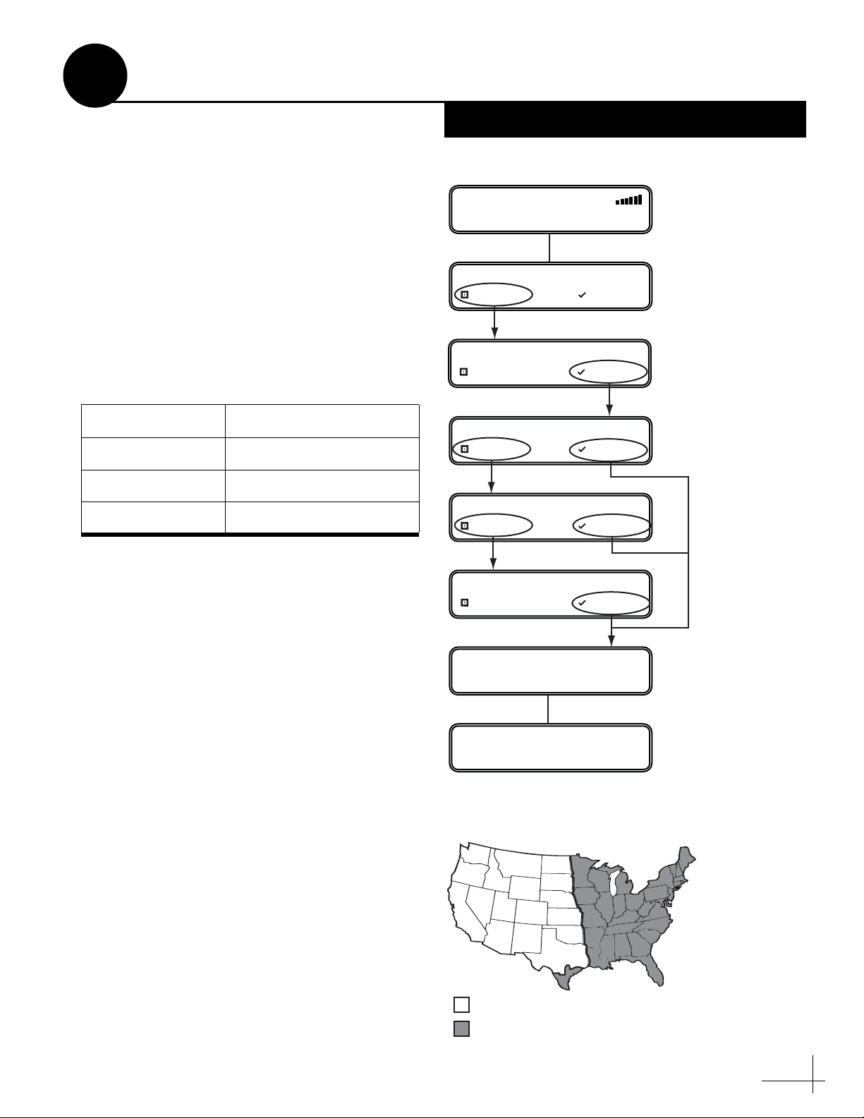
Figure 25: DISH Network Setup
Figure 26: Recommended Areas for DISH 1000 Satellites
11
Set Up the System
Follow these steps and refer to the flowchart in
Figure 25 to set up the system for DISH Network.
a. Press any button on the interface box front
panel.
b. At “Service= DIRECTV?,” press CHANGE
until the display shows “Service= DISH.”
Then press ACCEPT.
c. At “Mode= DISH 1000/129,” press CHANGE
until the display shows the desired mode.
Then press ACCEPT.
You may select any one of the following DISH
Network modes:
Mode Satellites Tracked
DISH 1000/129 119, 110, and 129
DISH 1000/61 119, 110, and 61
DISH 500 119 and 110
Option 1 - DISH Network
TRACKING DTV 101
SYSTEM NEEDS SETUP
SERVICE= DIRECTV?
CHANGE ACCEPT
SERVICE= DISH?
CHANGE ACCEPT
MODE= DISH 1000/129?
CHANGE ACCEPT
MODE= DISH 1000/61?
CHANGE ACCEPT
Press any button
to begin.
Press CHANGE until
desired mode displays;
then press ACCEPT.
DISH 1000/129 or DISH 1000/61
Select one of these modes for DISH Network’s
three-satellite service (DISH 1000). Use the map
in Figure 26 to help determine the appropriate
DISH 1000 mode for your geographic area. Check
with DISH Network for local channels
availability.
DISH 500
Select this mode if you wish to receive
programming from the 119 and 110 satellites for
DISH 500 service.
d. Be sure to follow the instructions in Step 12
(page 15) to enter your position and Step 13
(page 16) to set up your receiver(s).
MODE= DISH 500?
CHANGE ACCEPT
INSTALLING DISH SATS
RESTARTING ANTENNA
Displays satellites
installed for the
selected mode.
= DISH 129 Satellite Recommended
= DISH 61 Satellite Recommended
13
Page 14
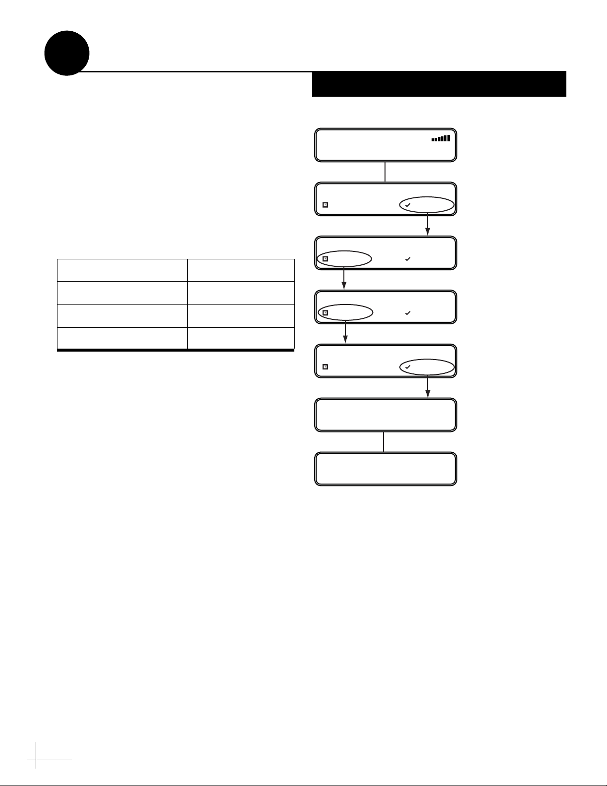
Figure 27: DIRECTV Setup
11
Set Up the System
Follow these steps and refer to the flowchart in
Figure 27 to set up the system for DIRECTV.
a. Press any button on the interface box front
panel.
b. At “Service= DIRECTV?,” press ACCEPT.
c. At “Mode= Tri-Sat Auto,” press CHANGE
until the display shows the desired mode.
Then press ACCEPT.
You may select any one of the following
DIRECTV modes:
Mode Satellites Tracked
Tri-Sat Auto Not used
Tri-Sat Pairs Not used
Dual-Sat 101 and 119
Tri-Sat Auto or Tri-Sat Pairs – Not Used
Do not use either of these modes for a new
installation. The Tri-Sat Auto mode supports the
Tri-Sat AutoSwitch; the Tri-Sat Pairs mode
supports the HDTV Converter. These HDTV
devices are no longer available.
Option 2 - DIRECTV
TRACKING DTV 101
SYSTEM NEEDS SETUP
SERVICE= DIRECTV?
CHANGE ACCEPT
MODE= TRI-SAT AUTO?
CHANGE ACCEPT
MODE= TRI-SAT PAIRS?
CHANGE ACCEPT
MODE= DUAL-SAT?
CHANGE ACCEPT
INSTALLING DTV SATS
101 119
RESTARTING ANTENNA
Press any button
to begin.
Press CHANGE until
DUAL-SAT is displayed.
Dual-Sat
Select this mode to receive programming from
the 101 and 119 satellites for DIRECTV service.
14
Page 15

Figure 28: Latitude/Longitude Setting
#
1
2
3
4
5
6
7
8
9
10
125° W
110° W
90° W
70° W
55° W
125° W
110° W
90° W
70° W
50° W
55° N
55° N
55° N
55° N
55° N
45° N
45° N
45° N
45° N
45° N
LAT
LONG
#
11
12
13
14
15
16
17
18
19
20
125° W
110° W
90° W
70° W
125° W
110° W
90° W
75° W
83° W
78° W
40° N
40° N
40° N
40° N
32° N
32° N
32° N
32° N
27° N
27° N
LAT
LONG
Figure 29: Latitude/Longitude Data for North America
12
Enter Your Latitude & Longitude
Follow these steps and refer to the flowchart in
Figure 28 to enter your vessel’s latitude and
longitude into the system. The antenna will use
your position information to speed up satellite
acquisition, which is critical for DISH Network
configurations. If the antenna knows where you
are, it knows where it should start looking for the
satellite.
If you don’t know your latitude/longitude,
simply use the latitude and longitude for your
region shown in Figure 29. For example, if you
are located in San Francisco, CA (region #11), you
would enter 40° N latitude and 125° W longitude.
a. Press MENUS on the interface box front
panel until the display shows “Lat/Long.”
b. At “Lat/Long= 41N, 071W,” press CHANGE.
c. Press CHANGE again. A cursor appears
under the first number in the displayed
latitude.
Press MENUS until LAT/LONG is displayed.
LAT/LONG= 41N, 071W
NEXT MENU CHANGE
LAT/LONG= 41N, 071W?
CHANGE ACCEPT
LAT/LONG= 41N, 071W
CHANGE ACCEPT
LAT/LONG= 55N, 125W?
CHANGE ACCEPT
RESTARTING ANTENNA
Press CHANGE to set
each digit plus N/S
(north or south) and
E/W (east or west).
Press ACCEPT to
save each digit.
d. Press CHANGE until the number is set to the
first digit of your vessel’s current latitude.
Then press ACCEPT. The cursor moves to the
next number.
e. Repeat Step d to set the remaining digits
(plus North/South and East/West directions)
of your latitude and longitude. Once you
have set the entire position, the cu rsor
disappears from the display.
f. Press ACCEPT. The antenna restarts. Wait
one minute for system startup.
15
Page 16
If you purchased a preconfigured DISH
receiver from KVH, you only need to run one
Check Switch test to set up the system.
IMPORTANT!
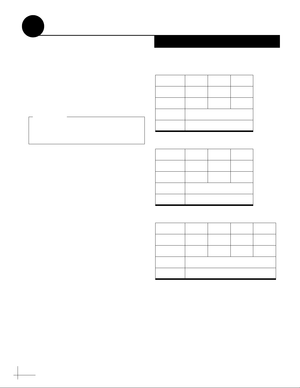
Figure 30: Expected Check Switch Results
DISH 1000/129 Results
DISH 1000/61 Results
DISH 500 Results
Port 123
Satellite 119 110 129
Trans OKOKOK
Status Reception Verified
Switch SW64
Port 123
Satellite 119 110 61.5
Trans OKOKOK
Status Reception Verified
Switch SW64
Input 1122
Satellite 119 119 110 110
Polarity Odd Even Odd Even
Status Reception Verified
Switch SW42
13
Run Check Switch Tests
If you set up the system for DISH Network,
follow these steps to run the receiver’s Check
Switch test as required.
Primary Receiver - 2 Check Switch Tests
Follow these steps to run two Check Switch tests
on the primary receiver, which is connected to
the “Unstacked Output” jack on the interface
box. This receiver will control satellite selection .
a. Make sure the vessel is docked in calm water
in a blockage-free area. Ensure the antenna
has an unobstructed view of the sky.
b. Apply power to the TV and receiver. (If the
antenna is turned off, turn it back on and wait
a few minutes for startup.)
DISH Network Only
c. Using the receiver’s remote, go to the “Point
Dish/Signal Strength” screen (press MENU,
6, 1, 1 on most models).
d. Choose Check Switch, then press SELECT.
e. Choose Test, then press SELECT.
f. Wait at least 15 minutes, or until the interface
box shows “Please run another Check
Switch,” before proceeding to allow the
antenna to find all of the satellites. Disregard
any messages on the TV; they do not correctly
indicate when the antenna is ready for the
next Check Switch test.
g. Once you have waited the proper amount of
time, choose Test, then press SELECT to run
a second Check Switch test.
h. Refer to the tables in Figure 30 and verify the
values displayed on your TV match those
required for your selected mode.
If your values match, exit the menu. The
receiver will download the program guide.
16
If your values do not match, follow the steps
on the next page to reset the system before
retrying this procedure.
Page 17

Figure 31: Factory Reset
Press MENUS until
DIAGNOSTICS= No is displayed.
DIAGNOSTICS= NO
NEXT MENU CHANGE
DIAGNOSTICS= YES?
CHANGE ACCEPT
ENTERING DIAGNOSTICS
SYSTEM RESET= YES?
CHANGE ACCEPT
SYSTEM RESET
RESET TO FACTORY?
ACCEPT EXIT
TRACKING DTV 101
SYSTEM NEEDS SETUP
SYSTEM RESET= NO
NEXT MENU CHANGE
13
Continued Run Check Switch Tests
Resetting the System Before Retrying
If the receiver Check Switch results displayed on
the TV do not match the expected values shown
in Figure 30 on page 16, follow these steps and
refer to the flowchart in Figure 31 to reset and
reconfigure the system.
a. On the interface box, press MENUS until the
display shows “Diagnostics= No.”
b. Press CHANGE until the display shows
“Diagnostics = Yes.” Then press ACCEPT.
c. At “System Reset= No,” press CHANGE
until the display shows “System Reset = Yes.”
Then press ACCEPT.
d. At “Reset to Factory?,” press ACCEPT.
e. Wait a few minutes for the syst em to reset to
its factory conditions.
f. When the display shows “System Needs
Setup,” repeat the setup procedure on
page 13 for the desired mode.
g. Be sure the vessel is docked in calm water,
and make certain the antenna has a clear,
unobstructed view of the sky.
h. Repeat the Check Switch steps on page 16.
DISH Network Only
Additional Receiver(s) - 1 Check Switch Test
If you connected multiple receivers, follow these
steps to run a Check Switch test on each
additional receiver (one at a time), unless it is a
preconfigured DISH receiver. When you are done,
reconnect the receivers as before.
a. Temporarily disconnect the primary receiver
from the “Unstacked Output” jack.
b. Connect the additional receiver to t he
“Unstacked Output” jack.
c. Perform Steps a - e on page 16 to run a single
Check Switch test on the receiver.
d. Wait 15 minutes, then verify the values on the
TV match the values shown in Figure 30 on
page 16. If your values do not match, try
running another Check Switch test.
17
Page 18

CAUTION
In the unlikely event that you need to
remove the radome, remove power from the
antenna first because the antenna’s moving
parts can cause injury.
Figure 32: Receiver Activation
Service: Call to Activate:
DISH
1-866-399-8509
(Mon.-Fri., 8:30 am - 5 pm ET)
DIRECTV
1-866-551-8004
(24 hours, 7 days a week)
TraracVisionision
Blocked!
Figure 33: Blockage Example
14
The installation process is complete! Before you
leave the vessel, test the system to verify the
antenna works properly. Then give the Customer
Welcome Kit and all manuals to the customer
and explain how to use the system. Also be sure
the customer understands the follow ing:
• Keep the radome installed on the antenna at
all times. The radome protects the antenna’s
moving parts from wind, rain, and debris.
• The receiver must be activated before it can
decode satellite TV signals. Refer to Figure 32
for activation details.
Educate the Customer
• The antenna must have a clear view of the
sky to receive satellite TV. Common causes of
blockage include trees, buildings, bridges,
and onboard equipment (see Figure 33).
Heavy rain or snow might also temporarily
interrupt reception.
• Clean the antenna regularly. Dirt buildup on
the radome can affect satellite TV reception.
• (DISH 1000 only) You may need to change
the operating mode when travelin g between
regions (see page 13 for details).
• Please register the system with KVH. The
registration process is quick, easy, online, and
ensures the best possible service from KVH.
Visit www.kvh.com/register or refer to the
Product Registration Form for details.
• The vessel must be located within the
selected satellite’s coverage area. To view
satellite coverage maps, visit: www.kvh.com/
footprint.
• Refer to the User’s Guide for complete
operation and troubleshooting information.
18
Page 19

www.kvh.com
KVH Industries, Inc.
Middletown, RI U.S.A.
Tel: +1 401 847 3327
Fax: +1 401 849 0045
E-mail: info@kvh.com
KVH Europe A/S
Kokkedal, Denmark
Tel: +45 45 160 180
Fax: +45 45 160 181
E-mail: info@kvh.dk
KVH Norway AS
Horten, Norway
Tel: +47 33 03 05 30
Fax: +47 33 03 05 31
E-mail: commboxsales@kvh.com
KVH Singapore
Singapore
Tel: +65 6829 2343
Fax: +65 6829 2121
E-mail: infokvhsingapore@kvh.com
 Loading...