

Page 1
TracVision® M1
with 12V DIRECTV® Mobile Receiver
M1 Installation Guide
®
TracVision
Page 2
TracVision M1 Installation Guide
DIRECTV® Mobile Receiver Configuration
These instructions explain how to install the TracVision M1 satellite TV antenna system on a
vessel. Complete instructions on how to use the system are provided in the User’s Guide.
Installation Steps
1. Inspect Parts and Get Tools...3
2. Plan the Installation...4
3. Prepare the Mounting Site...5
4. Wire the Antenna...6
5. Remove the Shipping Restraint...7
6. Mount the Antenna...8
7. Wire the Receiver...9
8. Connect Power...10
9. Mount the Receiver...11
10. Test the System...12
11. Educate the Customer...13
Who Should Install the System?
To ensure a safe and effective installation, KVH recommends that a KVH-authorized marine
technician install the TracVision M1 antenna. To find a technician near you, please visit
www.kvh.com/wheretogetservice.
Related Documentation
The following additional documents are provided with the TracVision M1 system:
Document
Description
User’s Guide Complete operation, setup, and troubleshooting
information
Quick Start Guide Handy quick reference to basic operation and
troubleshooting information
Product Registration Form Details on registering the product with KVH
Warranty Statement Warranty terms and conditions
Contents List List of every part supplied in the kit
Technical Support
If you need technical assistance, please contact KVH Technical Support:
Phone: +1 401 847-3327
E-mail: techs@kvh.com
(Mon.-Fri., 9 am-6 pm ET, Sat., 9 am-2 pm ET)
KVH, TracVision, and the unique light-colored dome with dark contrasting baseplate are registered trademarks of KVH Industries, Inc.
All other trademarks are property of their respective companies. The information in this document is subject to change without notice.
No company shall be liable for errors contained herein. © 2008 KVH Industries, Inc., All rights reserved. 54-0585 Rev. A
1
Page 3
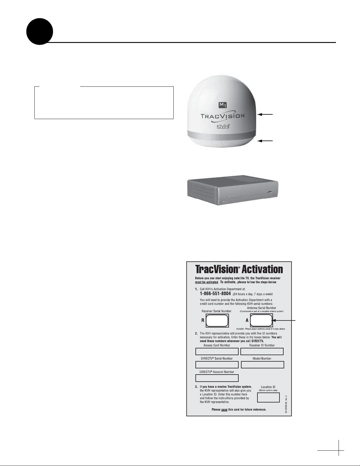
Always lift the antenna by the baseplate and
never by the radome or any portion of the
internal antenna assembly (see Figure 1).
IMPORTANT!
Mobile Receiver/Controller
Figure 1: TracVision M1 System Components
Figure 2: Activation Card
1
Before you begin, follow these steps to make sure
you have everything you need to complete the
installation.
a. Unpack the box and ensure it contains
everything shown on the Kitpack Contents
List. Save the packaging for future use.
b. Carefully examine all of the supplied parts to
ensure nothing was damaged in shipment.
c. Gather all of the tools and materials listed
below. You will need these items to complete
the installation.
Inspect Parts and Get Tools
Antenna
Radome
Baseplate
• #2 Phillips screwdriver
• 7/16" open-end wrench
• 3/8" socket or open-end wrench
• Electric drill and 1/4" (6 mm) bit
• Hole saw of desired diameter (for cable
access hole, see page 5)
• Silicone sealant or equivalent
•Adhesive tape
• Light hammer
• Center punch
• Eight 1/4" fasteners (see “Mount the
Receiver” on page 11)
d. Peel off the extra serial number label (taped
to the antenna) and affix it in the appropriate
box on the red Activation Card (see Figure 2).
XXXXXXXXX
XXXXXXXXX
Affix Serial
Number Here
3
Page 4
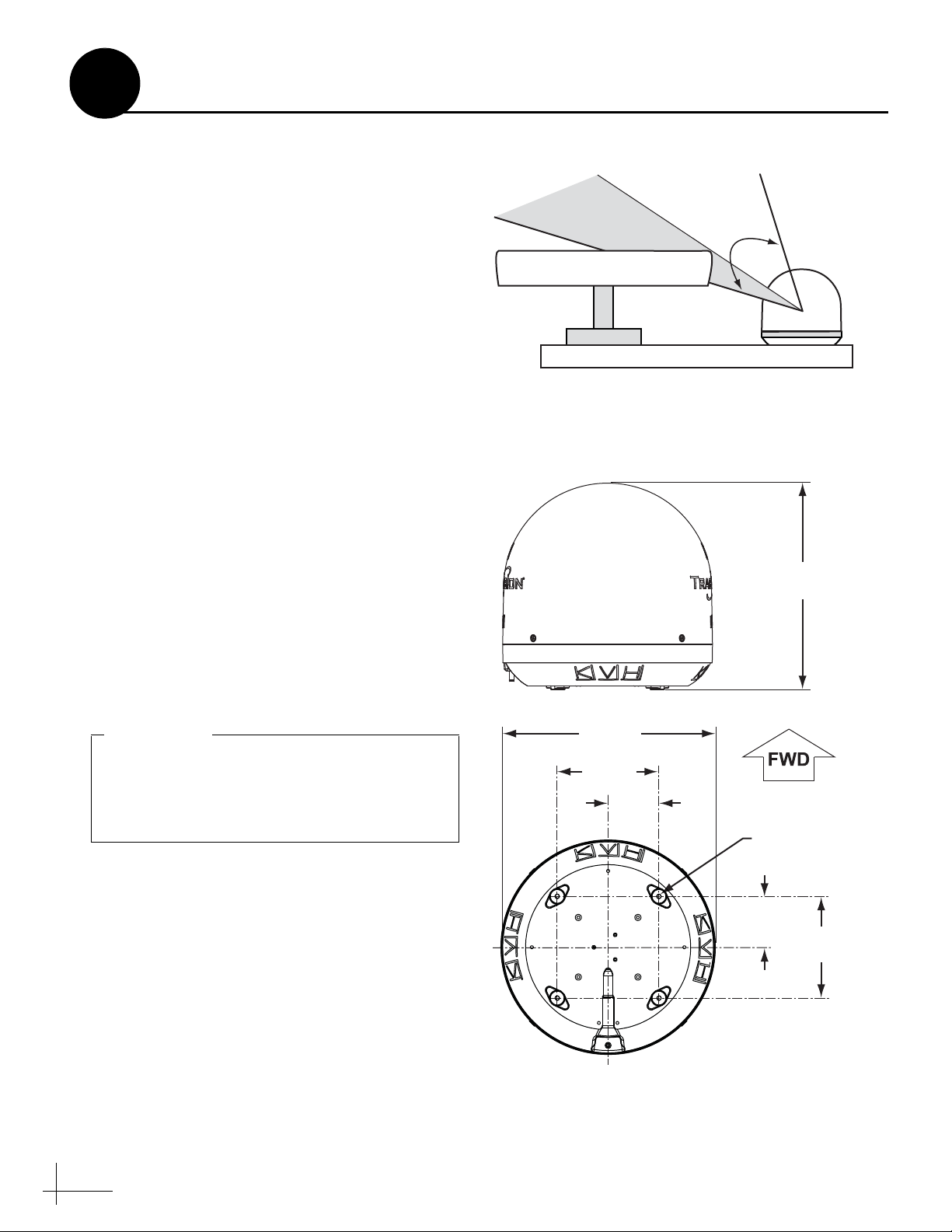
Antenna
Blocked!
17-73°
Vessel Platform
Radar
Figure 3: Blockage from Obstruction
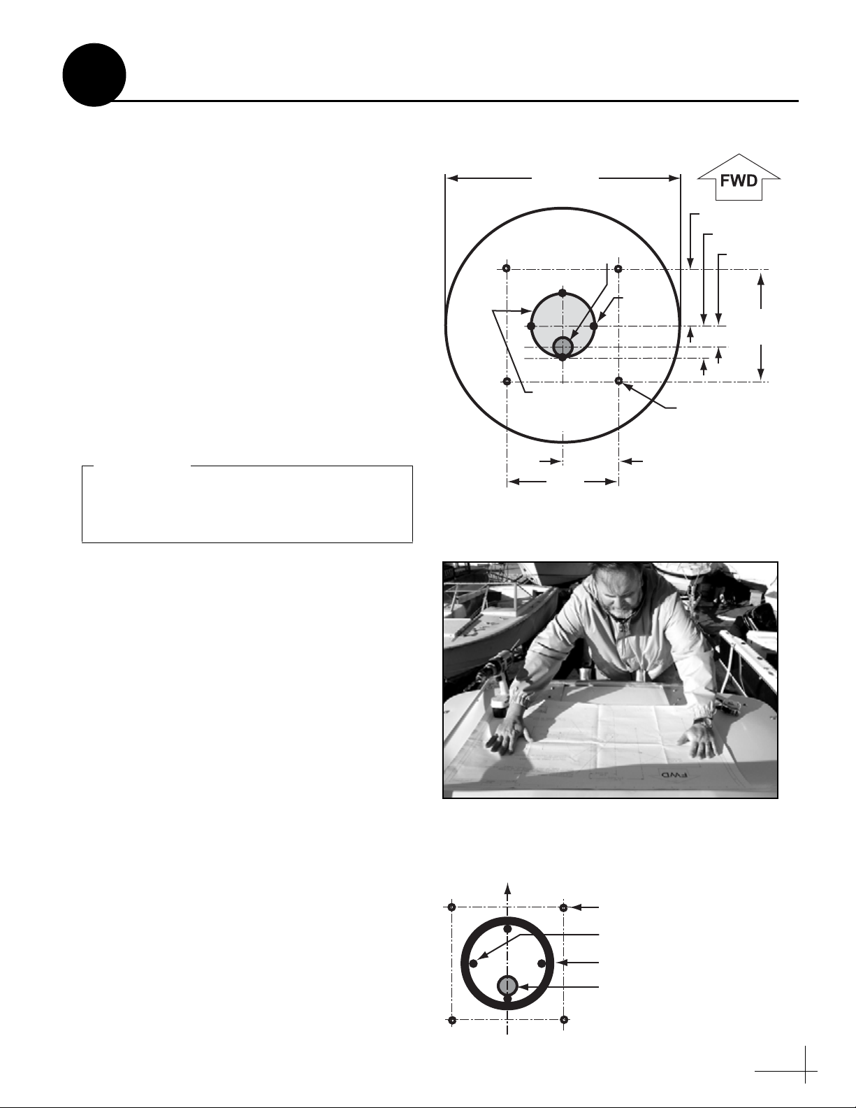
4 x Ø0.28"
(Ø7.04 cm)
Ø13.5"
(Ø34.3 cm)
6.4"
(16.3 cm)
3.2"
(8.1 cm)
3.2"
(8.1 cm)
6.4"
(16.3 cm)
Cable Connector
13.13"
(33.4 cm)
Figure 4: Antenna Dimensions
Do not shorten or extend the antenna cable.
Since the cable carries data, power, and
communications, the integrity of this cable
and its connections is very important.
IMPORTANT!
2
Before you begin, consider the following
installation guidelines:
• Minimize blockage. The antenna requires a
clear view of the sky to receive satellite TV
(see Figure 3). The fewer obstructions, the
better the system will perform.
• Make sure the mounting surface is wide
enough to accommodate the antenna’s base
(see Figure 4). Also make sure it is flat, level
(within ±2°), strong enough to support the
antenna’s weight (7.5 lbs), and rigid enough
to withstand vibration.
• Custom mounting solutions, including struts
and masts, are available from several thirdparty manufacturers. Contact your local KVH
dealer or distributor for details.
• KVH recommends that you do not mount the
antenna on the same level as the radar,
because the radar’s energy might overload
the antenna.
• Be sure to mount the antenna near enough to
the supplied receiver belowdecks to allow
you to connect the 50-ft. (15 m) coaxial cable
between the antenna and the receiver, while
still maintaining sufficient slack in the cable.
Plan the Installation
• When choosing a location for the receiver,
find a dry, well-ventilated area belowdecks
away from any heat sources or salt spray.
Also be sure the receiver’s front panel will be
easily accessible to the user.
4
Page 5
13.5"
(34.3 cm)
3.2" (8.1 cm)
6.4"
(16.3 cm)
3.2" (8.1 cm)
6.4"
(16.3 cm)
4 x Ø0.25"
(Ø0.6 cm)
Mounting Holes
Antenna Base
1.75" (4.4 cm)
1.25" (3.2 cm)
Maximum
Cable Access Hole
Ø3.5" (Ø8.9 cm)
Recommended
Cable Access Hole
Ø1.0" (Ø2.5 cm)
4 x Seal
Guides
Figure 5: Antenna Mounting Holes Layout
Figure 6: Using the Template to Mark Hole Locations
The diameter of the cable access hole must not
exceed 3.5" (89 mm) to maintain the integrity
of the foam seal.
IMPORTANT!
Figure 7: Foam Seal
3
Prepare the Mounting Site
Once you have identified a suitable antenna
mounting site, according to the guidelines
provided on page 4, follow these steps to prepare
the mounting site for installation.
a. Unfold the antenna mounting template
(supplied in the Customer Welcome Kit) and
place it onto the mounting surface. Make sure
the “FWD” (forward) arrow points toward
the bow and is parallel to the vessel’s
centerline (see Figure 5 and Figure 6). You
don’t need to mount the antenna exactly on the
centerline (the closer, the better), but the
antenna’s forward arrow must be parallel to it.
b. Mark the locations for the four mounting
holes on the mounting surface in the
locations indicated on the template.
c. Mark a location for the cable access hole.
KVH recommends a location 1.25" (32 mm)
aft of the center of the mounting hole pattern,
as shown on the template (see Figure 5). Size
the hole appropriately to maintain a cable
bend radius of at least 3" (75 mm).
d. Mark four seal guides in the locations
indicated on the template. Later, these guides
will help you position the foam seal correctly.
e. Drill a 1/4" (6 mm) hole at the four mounting
hole locations you marked in Step b. Later,
you will insert four #10-32 screws through
these holes to secure the antenna to the
mounting surface.
f. Using a hole saw, drill the cable access hole in
the location you marked in Step c. Smooth the
edges of the hole to protect the cable. Later,
you will route the antenna cable through this
hole and into the vessel.
g. Clean and dry the antenna mounting surface.
Bow
Mounting Holes (x4)
Guides (x4)
Foam Seal
h. Peel off the paper backing from the supplied
foam seal to expose the adhesive. Then press
the foam seal down firmly onto the mounting
surface, surrounding the guides and centered
between the mounting holes (see Figure 7).
Cable Access Hole
5
Page 6

Figure 8: Attaching the Rubber Feet
Be sure to install the rubber feet. They are
required to isolate the antenna from vibration.
IMPORTANT!
Figure 9: Connecting the Antenna Cable
Figure 10: Protecting the Connector with the Rubber Boot
Be sure to seal the cable access hole to prevent
water from leaking into the vessel.
IMPORTANT!
4
Follow these steps to connect the antenna cable to
the antenna.
a. First attach the four rubber mounting feet
(supplied in the kitpack) to the bottom of the
antenna at the locations shown in Figure 8.
b. Route the antenna cable belowdecks through
the cable access hole.
If you are routing the cable underneath the
antenna (normal installation):
Keep the end of the cable with the right-angle
connector and rubber sealing boot at the
antenna site. You may remove the straight
rubber boot at the opposite end of the cable
for easier cable routing, if necessary.
Wire the Antenna
If you are routing the cable straight down
from the connector (alternate installation):
Keep the straight connector and rubber
sealing boot at the antenna site.
c. Connect the cable to the antenna. Hand-
tighten, then tighten with a 7/16" wrench for
1/4 turn to ensure an electrical and weatherproof connection (see Figure 9).
d. Position the rubber boot over the connector to
help protect the connector from the elements
(see Figure 10).
e. Leave an adequate service loop,
approximately 8" (20 cm) of slack, in the
antenna cable for easy serviceability.
f. Weatherproof and seal the cable access hole
as required.
6
Page 7

Figure 11: Removing the Radome Screws
Figure 12: Removing the Radome
Figure 13: Removing the Shipping Restraint
5
Follow these steps to remove the shipping
restraint, which prevents the internal antenna
assembly from moving during shipment.
a. Remove the four #8-32 screws securing the
radome to the antenna (see Figure 11).
b. Carefully lift the radome straight up until
clear of the antenna assembly and set it aside
in a safe place (see Figure 12).
c. Using cutting pliers, cut and remove the tie-
wrap securing the antenna assembly to the
baseplate (see Figure 13).
d. Position the antenna onto the mounting
surface. The antenna’s base should rest
squarely atop the foam seal.
Remove the Shipping Restraint
7
Page 8

FORWARD
Figure 14: Aligning the “Forward” Arrows
Be sure to insert the mounting bolts from
above and use the supplied hardware for a
secure installation.
IMPORTANT!
Figure 15: Tightening the Mounting Bolts from Above
#10-32 x 3" Screw
#10 Flat Washer
(0.43" diameter)
Antenna Base
Foam Seal
Mounting Surface
#10 Flat Washer
(0.75" diameter)
#10 Lock Nut
Rubber Foot
Figure 16: Mounting Hardware
Use only manual hand tools to tighten the
mounting screws. The torque from a power
tool might warp the antenna baseplate.
IMPORTANT!
6
Follow these steps to mount the antenna to the
mounting surface.
a. Place the antenna baseplate over the holes
drilled in the mounting surface. Ensure the
“Forward” arrows inside the baseplate point
toward the bow and are parallel to the
vessel’s centerline (see Figure 14).
b. Secure the antenna’s baseplate to the
mounting surface using four #10-32 Phillips
screws, 0.43" flat washers, 0.75" flat washers,
and lock nuts, as shown in Figure 15 and
Figure 16.
Mount the Antenna
c. Using hand tools, tighten the bolts until the
foam seal is compressed and the antenna’s
four rubber feet are bottomed against the
mounting surface.
d. Reinstall the radome onto the antenna. The
radome’s “TracVision” labels should face
fore and aft. Secure the radome to the base
using the four #8-32 screws you removed
earlier.
8
Page 9

Do not shorten or extend the antenna cable.
Since the cable carries data, power, and
communications, the integrity of this cable
and its connections is very important.
IMPORTANT!
Be sure to route cables within the vessel
appropriately to avoid damage. For example,
do not route any cables through wet areas
(bilges) or near hot exhaust pipes. Also be
sure you do not kink the cable; maintain a
bend radius of at least 3" (75 mm).
IMPORTANT!
Figure 17: Wiring the Receiver
7
Wire the Receiver
Follow these steps to connect system cables to the
receiver.
Antenna
(A)
Deck
Receiver
a. Connect the antenna cable (A) to the “To
KVH Antenna” jack (see Figure 17).
b. Connect the RF converter cable (B) to the “RF
Remote Input” jack.
c. Connect the receiver to the TV’s video input.
Choose one of the following options:
Option 1 - RCA-type jack (cable included)
Option 2 - S-Video jack
NOTE: If the TV has only a coaxial input, you will
need an RF modulator (KVH part #72-0292).
d. Connect the receiver to the TV’s audio input.
Choose one of the following options:
To Video
(Option 2)
To Video
(Option 1)
Tested to comply
with FCC Standards
VIDEO AUDIO L AUDIO R
S-VIDEO
Y
RW
To Audio
(Option 1)
RF
REMOTE
INPUT
(B)
CAUTION
DIGITAL
AUDIO
OUT
RF Converter
TO
110W/HD
CONVERTER
To Audio
(Option 2)
TO KVH
ANTENNA
Option 1 - RCA-type jacks (cables included)
Option 2 - Digital audio jack
NOTE: For details on connecting additional receivers,
refer to Appendix A of the User’s Guide.
9
Page 10

CAUTION
For your own safety, disconnect vessel
power and make sure the circuit is dead
before you connect any power wires.
Figure 18: Receiver Power Wiring
8
The receiver requires 10-16 VDC power input
supporting 50 watts (4.2 amps @ 12 VDC). Follow
these steps to connect power to the receiver.
a. Before you connect the power wires, turn off
vessel power and test the circuit to ensure no
power is present.
b. Connect the individual power wires to a
dedicated 10-amp or 15-amp circuit breaker.
Connect the negative (black) wire to ground
(power return), and connect the positive (red)
wire to +12 VDC vessel power.
Connect Power
Powe r
Black
Red
Ferrite
Coil
Ground
Input Power
(10-16 VDC)
NOTE: As an alternative, you may use an AC/DC
power supply (KVH part #72-0206-01) to supply
power to the receiver.
c. Plug the other end of the wires into the
“Power” jack on the rear panel of the receiver
(see Figure 18).
NOTE: Do not remove the small ferrite coil that is
clamped onto the power wires. This coil suppresses
EMI (electromagnetic interference) from the receiver.
10
Page 11

Bracket
#2-56 x 1⁄4"
Screws (x3)
1⁄4" Fasteners (x4)
(not supplied)
Figure 19: Receiver Mounting
To avoid overheating, do not block the upper
vents of the receiver.
IMPORTANT!
Figure 20: RF Converter
Figure 21: Remote Control Batteries
9
Once all cables are connected, follow these steps
to install the receiver inside the vessel.
a. Attach the two mounting brackets to the
sides of the unit using three #2-56 screws.
Simply screw these fasteners into the vent
slots (see Figure 19).
b. Secure the brackets to the mounting surface
using appropriate 1/4" fasteners (not
supplied).
NOTE: Be sure to leave enough slack in the
connecting cables (service loop) for easy serviceability.
c. Place the RF converter at least 3 feet away
from the receiver (see Figure 20). If it is too
close to the receiver, the remote control might
not operate properly. Also avoid placing the
RF converter behind a metal surface or in an
area surrounded by metal.
Mount the Receiver
d. If desired, mount the RF converter using the
supplied Velcro fasteners.
e. Insert two AAA batteries (supplied in the
kitpack) in the remote control’s battery
compartment (see Figure 21).
AAA Batteries
11
Page 12

Figure 22: Receiver Power Switch and Status Lights
Figure 23: Program Guide Progress Bar
10
Now that you have installed the system, follow
these steps to turn the system on and verify that
the antenna works properly.
a. Ensure the antenna has a clear view of the
sky.
b. Apply power to the TV and the TracVision
system.
Test the System
c. Turn on the power switch on the front of the
receiver (see Figure 22).
d. Wait while the antenna searches the sky for
the DIRECTV satellite. Within a few minutes,
all three status lights on the front of the
receiver should be lit green (see Figure 22). If
all three status lights are not lit green, refer to
the User’s Guide for troubleshooting
information.
e. Wait one minute for the receiver to download
the program guide. A progress bar will
appear on the TV. (see Figure 23).
f. Once the program guide is loaded, verify that
you can view the DIRECTV preview channel
(channel 100).
Power Switch
Status Lights
12
Page 13

CAUTION
In the unlikely event that you need to
remove the radome, remove power from the
antenna first because the antenna’s moving
parts can cause injury.
Figure 24: Activation Card
TraracVisionision
Blocked!
Figure 25: Blockage Example
11
Before you leave the vessel, give the Customer
Welcome Kit, the red Activation Card, and all
manuals to the customer and explain how to use
the system. Also be sure the customer
understands the following:
Educate the Customer
• Keep the radome installed on the antenna at
all times. The radome protects the antenna’s
moving parts from wind, rain, and debris.
• The receiver must be activated first before it
can decode satellite TV signals. Refer to the
red Activation Card for details (see
Figure 24).
• The antenna must have a clear view of the
sky to receive satellite TV. Common causes of
blockage include trees, buildings, bridges,
and onboard equipment (see Figure 25).
Heavy rain or snow might also temporarily
interrupt reception.
XXXXXXXXX
XXXXXXXXX
• Clean the antenna regularly. Dirt buildup on
the radome can affect satellite TV reception.
• Please register the system with KVH. The
registration process is quick, easy, online, and
ensures the best possible service from KVH.
Visit www.kvh.com/register or refer to the
Product Registration Form for details.
• The vessel must be located within the
selected satellite’s coverage area. To view
satellite coverage maps, visit: www.kvh.com/
footprint.
• Refer to the User’s Guide for complete
operation and troubleshooting information.
13
Page 14

KVH Industries, Inc.
50 Enterprise Center Middletown, RI 02842-5279 U.S.A.
Phone: +1 401 847-3327 Fax: +1 401 849-0045
E-mail: info@kvh.com Internet: www.kvh.com
KVH Europe A/S
Kokkedal Industripark 2B 2980 Kokkedal Denmark
Phone: +45 45 160 180 Fax: +45 45 160 181
E-mail: info@kvh.dk Internet: www.kvh.com
© Copyright 2008 KVH Industries Inc. KVH, TracVision, and TracPhone are registered trademarks of KVH Industries Inc.
 Loading...