

Page 1

®
TracVision
HD7
Installation Guide
Page 2

TracVision® HD7 Installation Guide
These instructions explain how to install the TracVision HD7 satellite TV antenna system on a
vessel. Complete instructions on how to use the system are provided in the User’s Guide.
Installation Steps
1. Inspect Parts and Get Tools ................. 3
2. Plan the Antenna Installation .............. 4
3. Plan the ACU Installation .................... 5
4. Determine RF Cable Requirements..... 6
5. Prepare the Antenna Site...................... 7
6. Remove the Restraints .......................... 8
7. Wire the Antenna .................................. 9
8. Mount the Antenna ............................. 10
9. Mount the ACU ................................... 11
10. Wire the ACU....................................... 13
11. Wire for DIRECTV Service................. 14
12. Configure Each Receiver/DVR ......... 16
13. Connect the ACU to the Network..... 17
14. Update the Software if Necessary..... 21
15. Educate the Customer......................... 22
Who Should Install the System?
To ensure a safe and effective installation, KVH recommends that a KVH-authorized marine
technician install the TracVision antenna. KVH-authorized technicians have the tools and
electronics expertise necessary to install the system. To find a technician near you, visit
www.kvh.com/wheretogetservice.
Technical Support
If you need technical assistance, please contact KVH Technical Support:
Phone: +1 401 847-3327
E-mail: techs@kvh.com
(Mon.-Fri., 9:00 am - 6:00 pm Eastern)
(Sat., 9:00 am - 2:00 pm Eastern)
KVH, TracVision, and the unique light-colored dome with dark contrasting baseplate are registered trademarks of
KVH Industries, Inc. All other trademarks are property of their respective companies. The information in this document is subject to
change without notice. No company shall be liable for errors contained herein. © 2009 KVH Industries, Inc., All rights reserved.
54-0662 Rev. B
1
Page 3
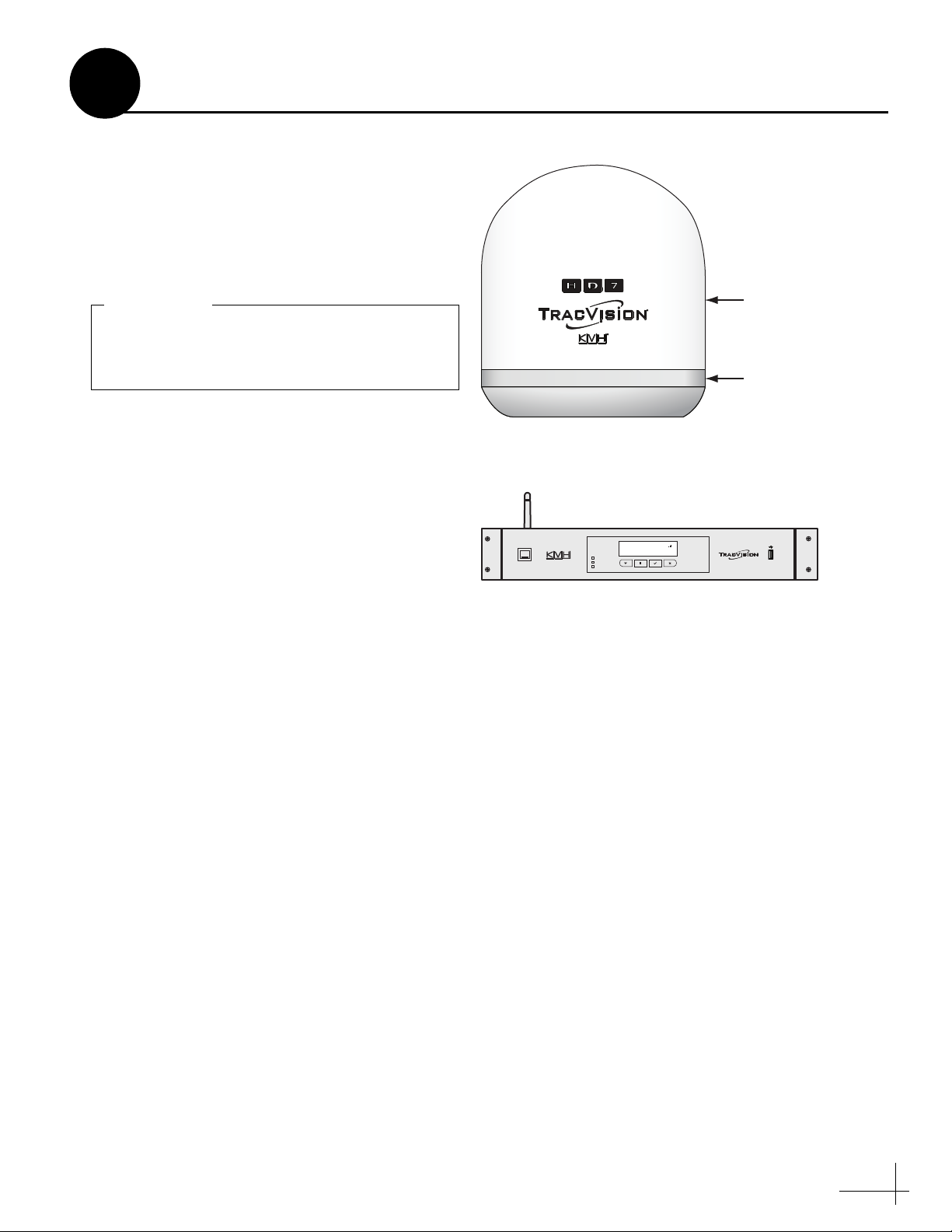
Always lift the antenna by the baseplate and
never by the radome or any portion of the
internal antenna assembly (see Figure 1).
IMPORTANT!
1
Radome
Baseplate
Inspect Parts and Get Tools
Before you begin, follow the steps below to
ensure you have everything needed to complete
the installation.
a. Unpack the box and ensure it contains
everything shown on the Kitpack Contents
List. Save the packaging for future use.
b. Carefully examine all of the supplied parts to
ensure nothing was damaged in shipment.
c. Gather the tools and materials listed below.
You will need these items to complete the
installation.
• #0 Flat-head screwdriver
• #1 Phillips screwdriver
Figure 1 TracVision HD7 Antenna
Figure 2 Antenna Control Unit (ACU)
TRACKING SATS
CONTROL UNIT
ANTENNA
POWER
DIRECTV 99-101-103
CHANGE
ACCEPT
MENU
EXIT
®
• #2 Phillips screwdriver
• Electric drill and 1/2" (13 mm) drill
bit
• 3" (80 mm) hole saw
• 5/8" open-end wrench
• 9/16" nut driver or wrench
• 7/16" open-end wrench
• Light hammer and center punch
• Wire strippers and terminal lug
crimper
•Cutting pliers
• RG-6 or RG-11 RF coax cabling with
®
Snap-N-Seal
F-connectors; refer to
Step 4 on page 6 for details
• Satellite TV receivers and/or DVRs
• Surge protector or uninterruptible
power supply (UPS) (recommended)
3
Page 4
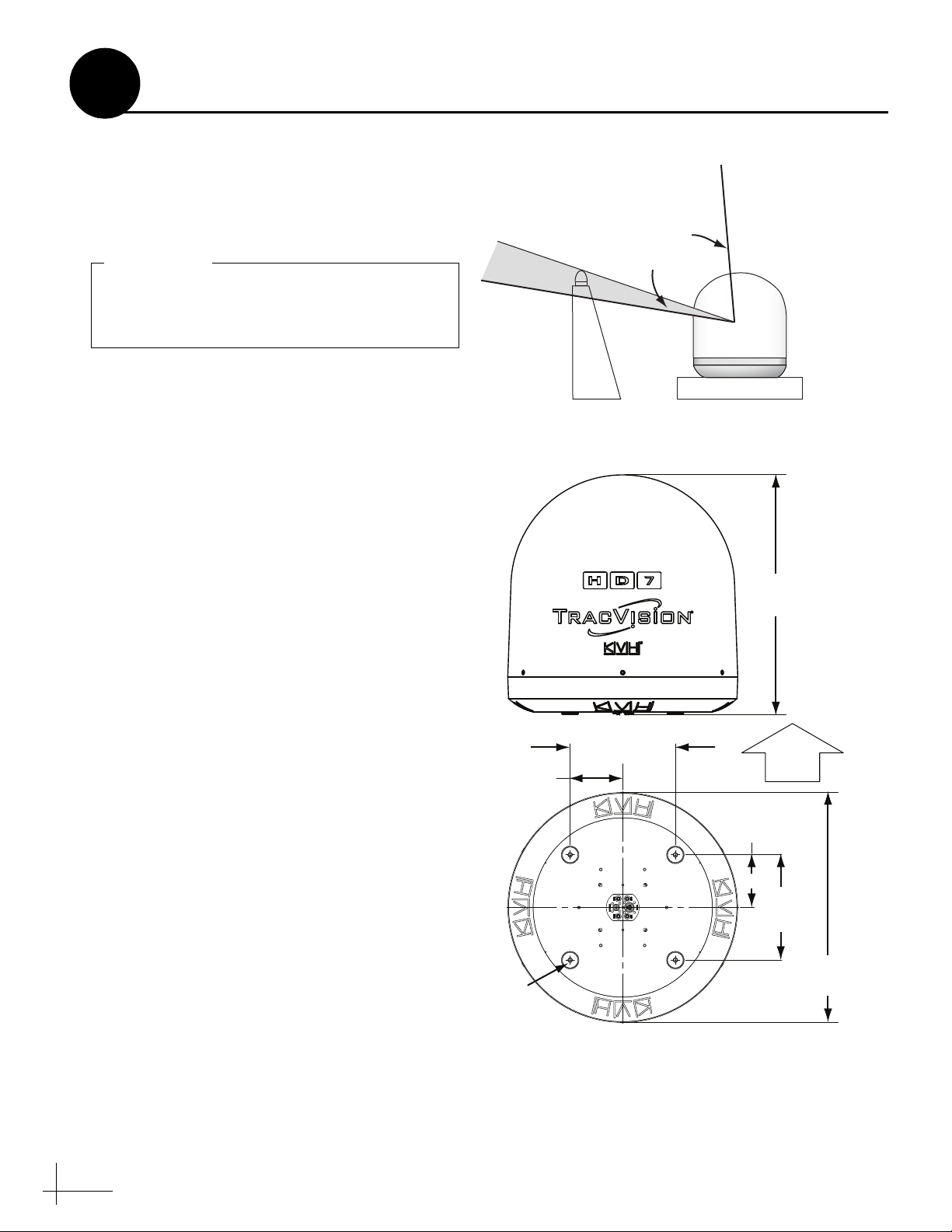
Do not mount the antenna at the same level as
the radar because the radar’s energy will
overload/damage the antenna’s LNB.
IMPORTANT!
FWD
12"
[30.5 cm]
27.28"
[69.3 cm]
6"
[15.2 cm]
6"
[15.2 cm]
12"
[30.5 cm]
Ø.50"
[1.3 cm]
Ø26"
[66.6 cm]
2
Plan the Antenna Installation
Before you begin, consider the following antenna
installation guidelines:
• The antenna must be mounted outside the
radar’s beam pattern.
• Minimize blockage. The antenna requires a
clear view of the sky to receive satellite TV
(see Figure 3). The fewer obstructions, the
better the system will perform.
• Make sure the mounting surface is wide
enough to accommodate the antenna’s base
(see Figure 4). Also make sure it is flat, level
(within ±1°), strong enough to support the
antenna’s weight (61 lbs (28 kg)), and rigid
enough to withstand vibration.
Figure 3 Blockage from Obstruction
15° to 75°
Look Angle
Blocked!
Mast
Figure 4 Antenna Dimensions
Vessel Platform
Antenna
• Select a location that is as close as possible to
the intersection of the vessel’s fore-and-aft
centerline and midships.
• The antenna must be located within 100 ft
(30 m) of the ACU.
4
Page 5
3
Plan the ACU Installation
Before you begin, consider the following ACU
installation guidelines:
• Select an ACU mounting location in a dry,
well-ventilated area belowdecks away from
any heat sources or salt spray.
• The ACU’s front panel should be easily
accessible to the user.
• Ensure the supplied router location provides
adequate WiFi reception. Do not install it in
an area surrounded by metal or near any
electrical devices that emit RF noise.
• The ACU must be located within 100 ft (30 m)
of the antenna.
• You can choose from two ACU mounting
options:
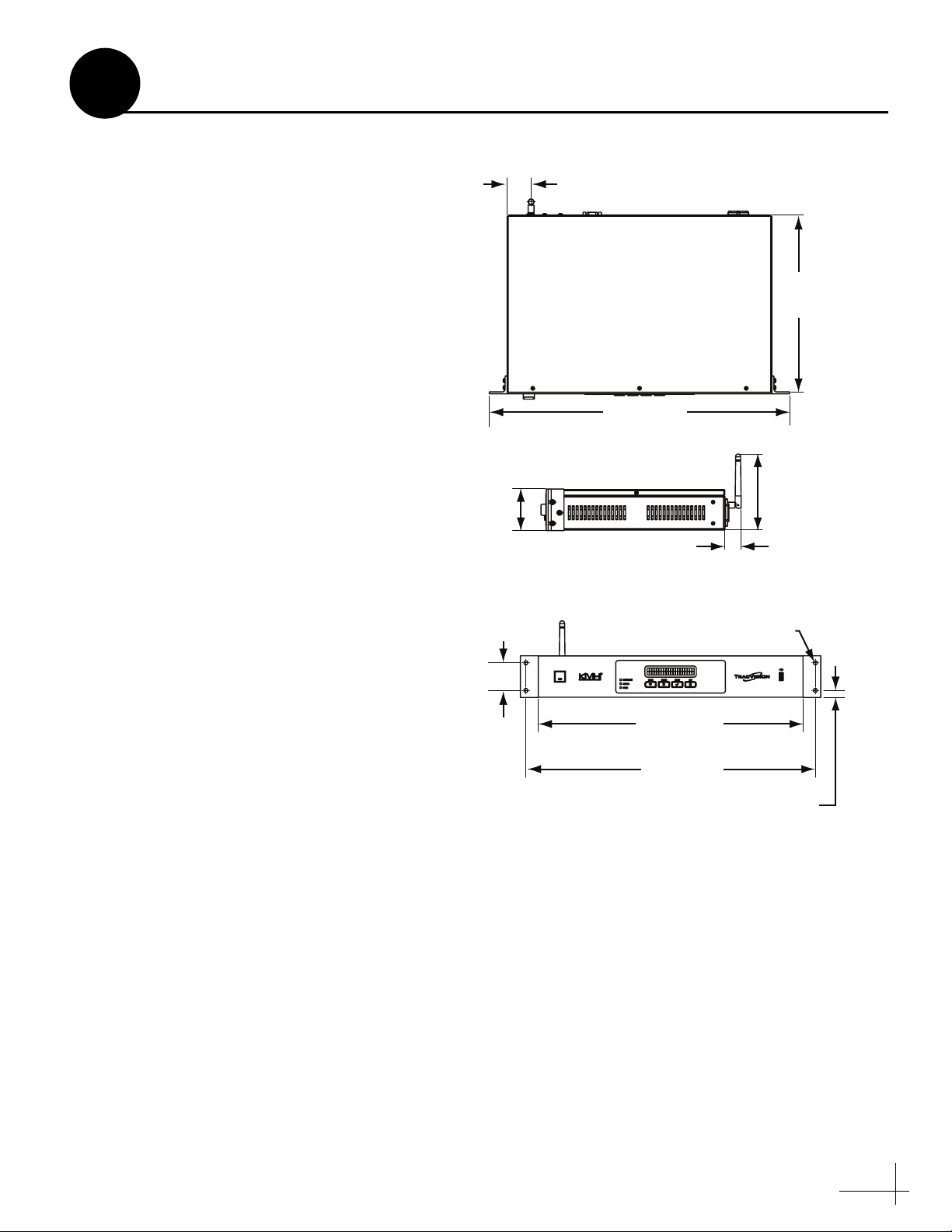
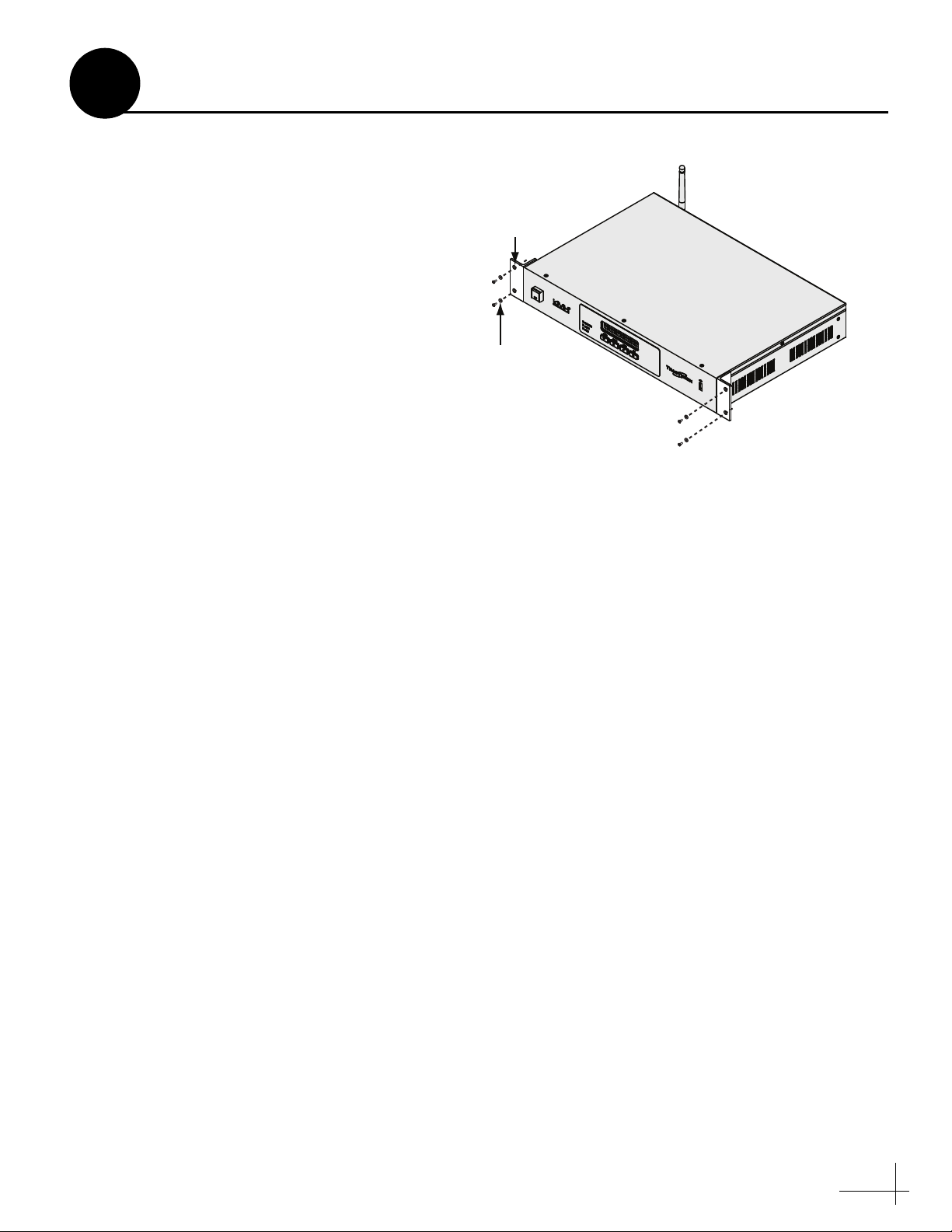
Option A - Equipment Rack Mounting
Figure 5 ACU Dimensions
1.52"
[3.8 cm]
[48.26 cm]
2.63"
[6.68 cm]
11.18"
[28.40 cm]
19.00"
4.81"
[12.22 cm]
1.02"
[2.60 cm]
If desired, you can mount the ACU in a standard
19" (482.6 mm) equipment rack.
NOTE: The ACU is 1.5U in height.
Option B - Horizontal Surface Mounting
If desired, you can remove the rack-mount
brackets from the front panel of the ACU, and
secure the ACU underneath or on top of a
horizontal surface using the supplied horizontal
mounting brackets.
1.75"
[4.45 cm]
16.75"
[42.55 cm]
18.31"
[46.51 cm]
4X
Ø.25"
[0.64 cm]
[1.12 cm]
0.44"
5
Page 6
4
Determine RF Cable Requirements
Follow the instructions below to determine the
quantity and type of RF cables needed.
What Type of RF Cables are Needed?
To ensure optimal performance, refer to the table
below to select the required RF cable type for
your installation.
For Lengths Use RF Cable Type
Up to 100 ft (30 m) RG-6
100 ft (30 m) to
RG-11
200 ft (61 m)
NOTE: Only use RF cable lengths 200 ft (61 m) or
less.
How Many RF Cables are Needed?
The number of RF cables varies according to the
quantity of receivers and/or DVRs. Consider the
following guidelines.
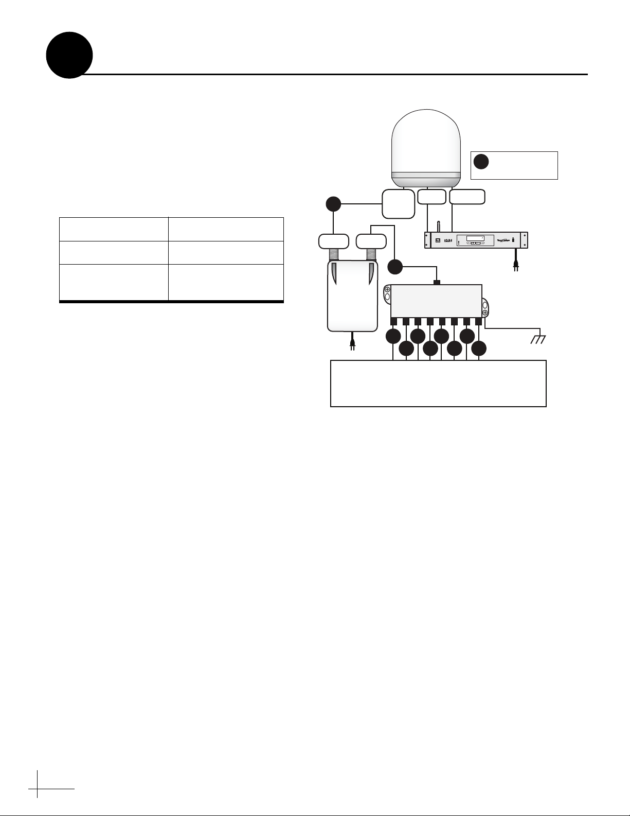
Figure 6 Typical Wiring (DIRECTV Only)
Antenna
=
RG-6/RG-11
RF
RF Cable
RF
SWM
Power
Inserter
SWM
Data
(RF1)
IRDSWM
RF
8-Way Splitter
RF
RF RF RF RF
Power
TRACKING SATS
DIRECTV 99/101/103
®
CONTROL UNIT
MENU
ANTENNA
POWER
RFRFRF
CHANGE
EXIT
ACCEPT
Vessel
AC Ground
Supports up to 8 Tuners
Each SWM Receiver = 1 Tuner = 1 RF Cable
Each DVR = 2 Tuners = 1 RF Cable
ACU
• Since the 8-way splitter supports up to 8
tuners, you can connect any number of SWM
receivers/DVRs that adds up to 8 tuners or
less.
• Each receiver has a single tuner, and requires
one RF cable. Each DVR has two tuners, and
requires one RF cable.
NOTE: One 100 ft (30 m) RG-11 RF cable is supplied
with the TracVision HD7 system.
NOTE: Refer to Step 11 on page 14 for complete
receiver/DVR connection instructions.
What Type of RF Cable Connectors are
Needed?
Be sure to use only Snap-N-Seal F-type
connectors. Twist-on connectors and other lowquality connector types degrade performance.
6
Page 7
5
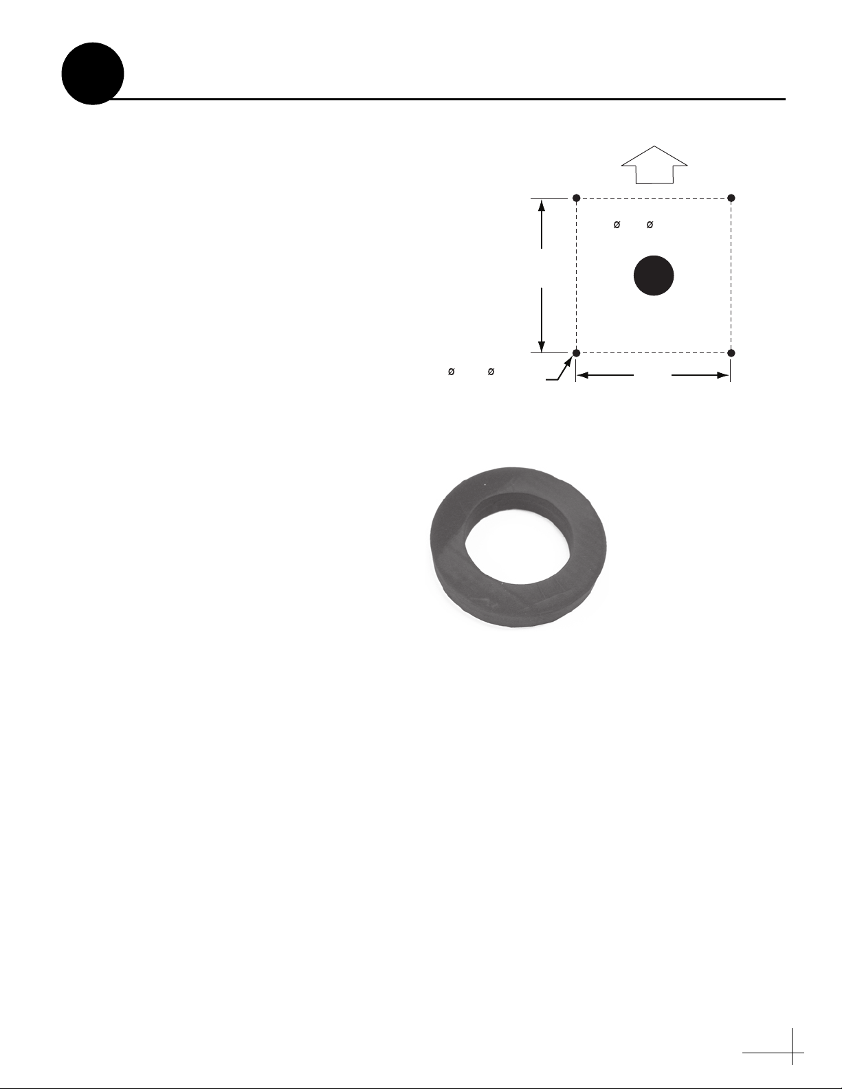
Prepare the Antenna Site
Follow the steps below to drill the antenna’s
mounting holes and cable access hole.
a. Unfold the antenna mounting template
(supplied in the Customer Welcome Kit) and
place it onto the mounting surface. Make sure
the “FWD” (forward) arrow points toward
the bow and is parallel to the vessel’s
centerline (see Figure 7).
b. Using a light hammer and center punch,
mark the locations for the four mounting
holes and cable access hole on the mounting
surface in the locations indicated on the
template.
c. Drill a 1/2" (1.3 cm) hole at the four mounting
hole locations. Later, you will insert four
3/8"-16 bolts through these holes to secure
the antenna to the mounting surface.
d. Cut out the 3" (8 cm) hole at the cable access
hole location. Smooth the edges of the hole to
protect the cables. Later, you will route the
cables through this hole and into the vessel.
e. Clean and dry the antenna mounting surface.
Figure 7 Antenna Mounting Holes Layout
3" ( 8 cm)
Cable Access Hole
12"
(30.5 cm)
1/2" ( 1.3 cm)
Mounting Hole (x4)
Figure 8 Foam Seal
Align with
Cable Access
Hole
(30.5 cm)
FWD
12"
f. Peel off the paper backing from the supplied
foam seal to expose the adhesive.
g. Press the foam seal down firmly onto the
mounting surface (not the antenna’s
baseplate), ensuring the hole in the foam seal
aligns with the cable access hole in the
mounting surface (see Figure 8).
NOTE: Apply the foam seal to the vessel mounting
surface, not to the antenna’s baseplate. You will have
difficulty connecting the cables to the antenna if the
foam seal is attached to the baseplate.
7
Page 8
Screw (x6)
Radome
Baseplate
Bracket
and Bolt (x2)
Bolt and
Washer (x2)
6
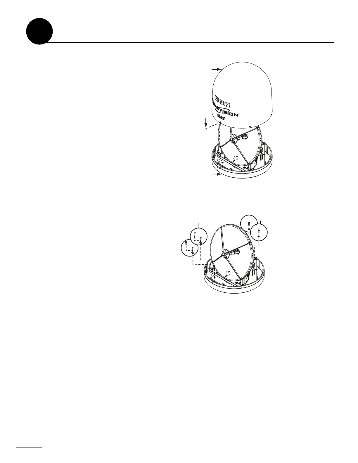
Remove the Restraints
Internal restraints prevent the antenna assembly
from moving during shipment. Follow these
steps to remove these shipping restraints.
NOTE: Be sure to keep the shipping restraint
hardware for future use.
a. Using a #2 Phillips screwdriver, remove the
six #10-32 Phillips screws securing the
radome to the baseplate (see Figure 9).
b. Carefully lift the radome straight up off the
antenna. Then set it aside in a safe place.
c. Using a 9/16" nut driver or wrench, remove
the four bolts, two brackets, and two washers
securing the antenna to the shipping pallet
(see Figure 10).
NOTE: You will remove additional shipping
restraints after you mount the antenna.
Figure 9 Radome Screws
Figure 10 Shipping Restraints
8
Page 9
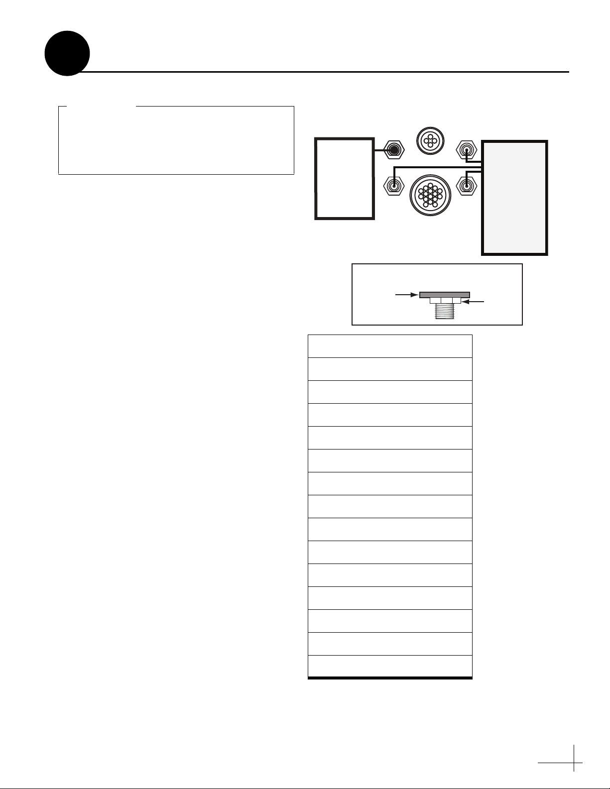
To ensure the RF cables are fully seated
during connection, ensure the sealing nuts on
the antenna’s RF connectors are flush with the
antenna base before you connect RF cables.
IMPORTANT!
SWM
(RF1)
RF4
RF2
RF3
POWER
DATA
For
DIRECTV
SWM
Receivers
and DVRs
Only
For nonSWM
Receivers
Only (DISH
Network,
Bell TV,
Legacy
DIRECTV
Receivers)
Sealing
Nut
Antenna
Base
Proper Sealing Nut Position
7
Wire the Antenna
.
Connect the Power and Data Cables
Connect and hand-tighten the data and power
cables to the antenna (see Figure 11).
Connect an RF Cable to SWM (RF1)
a. Connect an RF cable to the antenna’s SWM
(RF1) connector. Then, using a 7/16" openend wrench, tighten the RF cable for 1/4 turn.
b. Using a 5/8" open-end wrench, turn the
sealing nut on the connector (between the RF
cable and the antenna) until the O-ring forms
a seal against the F-connector.
Figure 11 Antenna Connectors/Compatible Receivers
SWM Receiver/DVR Models*
HR20
HR21
Connect Additional RF Cables - Non-SWM
Receivers/DVRs Only
Follow the instructions below if you need to
connect non-SWM receivers/DVRs. Non-SWM
receivers/DVRs include Bell TV, DISH Network,
and legacy DIRECTV receivers.
NOTE: SWM-compatible receivers/DVRs are listed
in the table at right.
a. Connect RF cables to the antenna’s RF2 and
RF3 connectors (see Figure 11).
b. Using a 7/16" open-end wrench, tighten the
c. Label the ends of the SWM (RF1), RF2, and
Route Cables
Route the cables belowdecks through the cable
access hole. Leave an adequate service loop,
approximately 8" (20 cm) of slack, in the cables
for easy serviceability.
RF cables to the antenna for 1/4 turn. Then
using a 5/8" open-end wrench, turn the
sealing nut on the connector until the O-ring
forms a seal against the F-connector.
RF3 cables for easy identification later.
HR21 Pro
HR22
HR23
H20
H21
H22
H23
R16
R22
R23
D12
D13
*NOTE: Additional SWM-compatible receivers/DVRs
might become available at any time. If your receiver or
DVR model is not listed here, check the receiver’s/
DVR’s manual to see if it is SWM-compatible.
9
Page 10
You will need to rotate the antenna assembly
by hand to see all four mounting holes. Rotate
the antenna assembly slowly to avoid
damaging the antenna.
IMPORTANT!
IMPORTANT
Tie-wrap
Tie-wrap
IMPORTANT
8
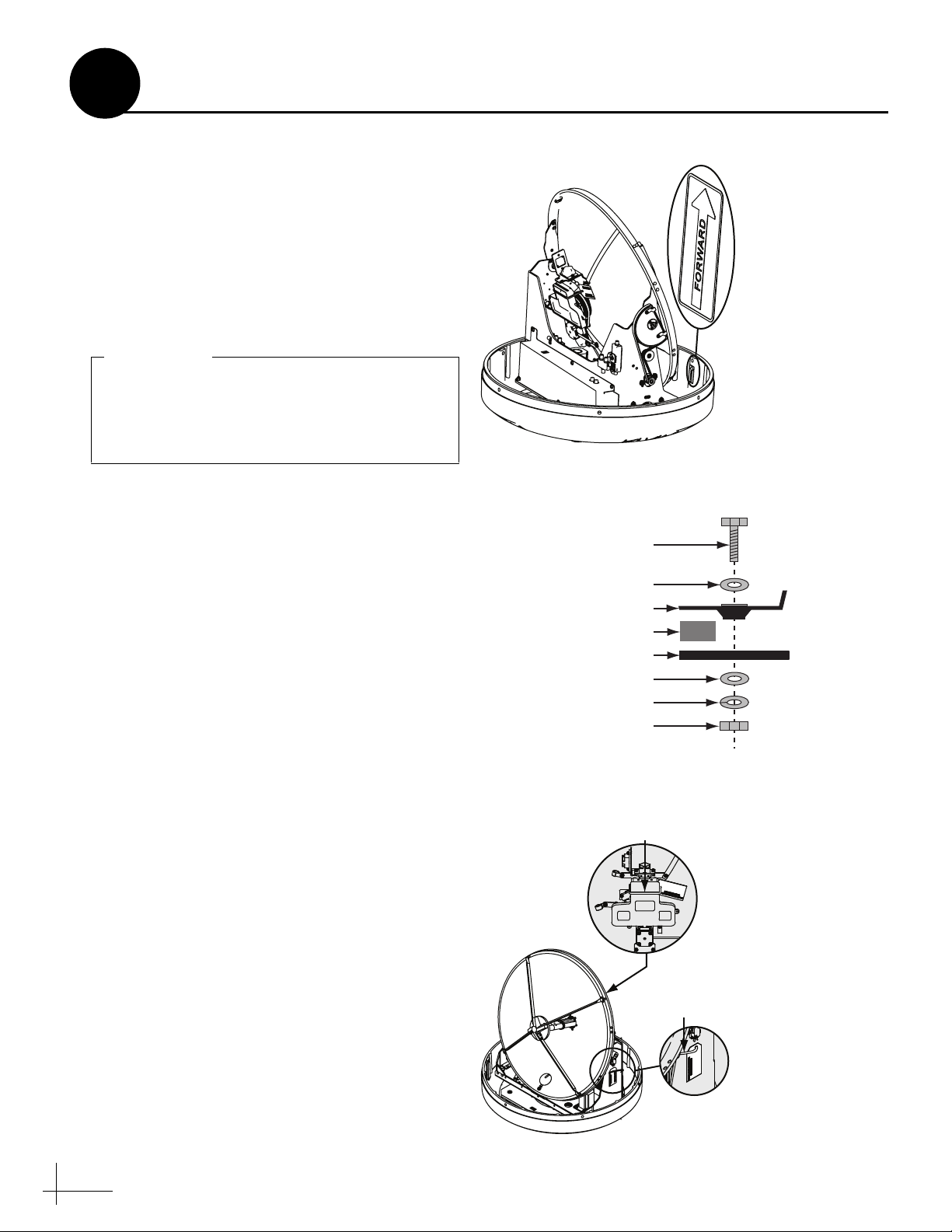
Mount the Antenna
Follow the steps below to mount the antenna to
the mounting surface.
a. Place the antenna baseplate over the holes
drilled in the mounting surface.
b. Ensure the forward arrow inside the
baseplate points toward the bow and is
parallel to the vessel’s centerline (see
Figure 12).
c. At each of the four baseplate mounting holes,
place a 3/8" fender washer on a 3/8"-16 bolt
and insert the bolt into the hole from above
(see Figure 13).
d. Secure each mounting bolt to the mounting
surface using a 3/8" flat washer, a 3/8" lock
washer, and a 3/8"-16 hex nut from below
(see Figure 13).
e. Tighten all four bolts until the four rubber
feet on the baseplate are bottomed against the
mounting surface and the foam seal is fully
compressed.
Figure 12 Forward Arrow Location
Figure 13 Antenna Mounting
3/8"-16 Bolt (x4)
3/8" Fender Washer (x4)
Antenna Base
Foam Seal
Mounting Surface
3/8" Flat Washer (x4)
3/8" Lock Washer (x4)
3/8"-16 Hex Nut (x4)
Using cutting pliers, cut and remove both of
f.
the tie-wraps equipped with paper tags (see
Figure 14).
g. Reinstall the radome onto the antenna. Secure
the radome in place using the six #10-32
screws you removed in Step 6 on page 8.
h. Install a plastic screw cap (supplied in the kit)
over the six radome screws.
10
Figure 14 Shipping Restraint Tie-wraps
Page 11
Mounting
Hole (x4)
M6 Screw
and Washer (x4)
9
Mount the ACU
Follow the steps below to mount the ACU to a
standard 19" (482.6 mm) equipment rack, or
above or beneath a horizontal surface.
Option A - Equipment Rack Mounting
a. Align the four mounting holes on the front
panel of the ACU, to the mounting holes on
the equipment rack (see Figure 15).
b. Secure the ACU to the equipment rack using
four M6 screws and washers (see Figure 15).
Figure 15 ACU Equipment Rack Mounting
11
Page 12

Horizontal Mounting
Bracket (x2)
#6-32 Screw and
#6 Washer (x4)
Horizontal Mounting
Bracket (x2)
#6-32 Screw and
#6 Washer (x4)
9
Continued Mount the ACU
Option B - Horizontal Mounting
a. Using a #1 Phillips screwdriver, remove the
six screws securing the rack mounting
brackets to the sides of the ACU (see
Figure 16).
b. Using a #1 Phillips screwdriver, secure the
mounting brackets to the sides of the ACU in
the bracket orientation for your installation
(see Figure 17 or Figure 18). Then secure the
mounting brackets using four supplied #6-32
Phillips screws and #6 washers.
c. Using fasteners appropriate for the mounting
surface, secure the ACU to the mounting
surface using the four mounting bracket
holes.
Figure 16 ACU Rack Mounting Bracket Removal
Rack Mounting
Bracket (x2)
Screw (x6)
Figure 17 Horizontal Mounting Bracket Orientation
12
Figure 18 Horizontal Mounting Bracket Orientation
Page 13

RS232
Wi-Fi
KVH and TracVision are registered
trademarks of KVH Industries, Inc.
Tested to comply
with FCC Standards
Meets requirements
ANTENNA
ETHERNET
AC INPUT
100-240V~
160W MAX
50/60 HZ
FUSE
3.15A
250V~
FAST ACTING
This device complies with Part 15 of the FCC rules. Operation is subject
to the following two conditions: (1) This device must not cause harmful
interence, and (2) This device must accept any interference received,
including interference that may cause undesired operation.
RISK OF ELECTRIC SHOCK
DO NOT OPEN
CAUTION
Red (+42V)
Black (Gnd)
Not Used
Wht/Gry
Gry/Wht
Wht/Org
Org/Wht
Not Used
Wht/Brn
Brn/Wht
Wht/Blu
Blu/Wht
Terminal
Board
120 VAC
Power
Cord
RS232
Wi-Fi
KVH and TracVision are registered
trademarks of KVH Industries, Inc.
Tested to comply
with FCC Standards
Meets requirements
ANTENNA
ETHERNET
AC INPUT
100-240V~
160W MAX
50/60 HZ
FUSE
3.15A
250V~
FAST ACTING
This device complies with Part 15 of the FCC rules. Operation is subject
to the following two conditions: (1) This device must not cause harmful
interence, and (2) This device must accept any interference received,
including interference that may cause undesired operation.
RISK OF ELECTRIC SHOCK
DO NOT OPEN
CAUTION
Red (+42V)
Black (Gnd)
Not Used
Wht/Gry
Gry/Wht
Wht/Org
Org/Wht
Not Used
Wht/Brn
Brn/Wht
Wht/Blu
Blu/Wht
ETHERNET
10
Wire the ACU
Follow the steps below to wire the ACU.
a. Dress the data and power cables from the
antenna. Using wire strippers, strip back the
insulation of each wire approximately 1/4"
(6 mm) and gently twist each wire to ensure a
good electrical connection.
b. Locate the ACU terminal strip connector
supplied in the kitpack (see Figure 19).
c. Connect the data cable wires to the terminal
board connector, as shown in Figure 19. Then
using a #0 flat-head screwdriver, tighten each
terminal screw to secure the wires in place.
d. Connect the power cable wires to the
terminal strip connector, as shown in
Figure 19. Then using a #0 flat-head
screwdriver, tighten both terminal screws to
secure the wires in place.
e. Press and lock the terminal strip connector
into place on the rear of the ACU (see
Figure 20).
f. Connect one end of the ACU’s 120 VAC
power cord to the rear of the ACU (see
Figure 20). Then connect the other end into a
UPS or surge protector.
Figure 19 Terminal Strip Connector
Power Cable
12 1110987612543
12 1110987612543
Red (+42V)
Black (Gnd)
Not Used
Terminal
Screw (x12)
Not Used
Wht/Gry
Gry/Wht
Wht/Org
Org/Wht
Data Cable (Body Color/Strip Color)
Figure 20 Terminal Strip/Power Supply
Blu/Wht
Wht/Blu
Brn/Wht
Wht/Brn
g. Optional - If you plan to connect the ACU to
an onboard network using the supplied
Ethernet cable, connect it to the ACU’s
Ethernet port (see Figure 21).
Figure 21 Ethernet Port
13
Page 14
This section explains how to wire SWM
receivers/DVRs for DIRECTV service. If you
need to install non-SWM receivers/DVRs,
refer to the wiring diagrams in Appendix B
on page 29.
IMPORTANT!
11
Wire for DIRECTV Service
Follow the steps below to wire the TracVision
HD7 system for DIRECTV service.
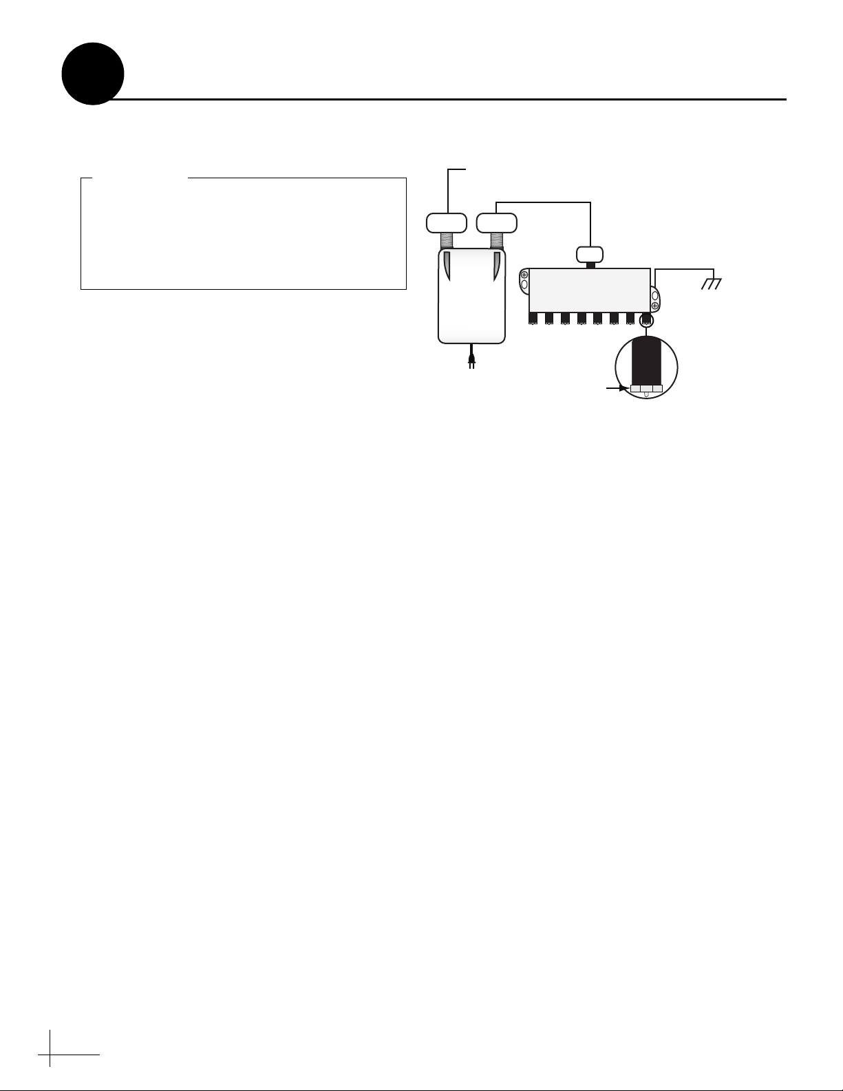
Connect the Power Inserter and Splitter
a. Attach a Snap-N-Seal F-type connector to the
SWM (RF1) cable from the antenna. Then
connect the cable to the power inserter’s
SWM connector (see Figure 22).
b. Connect one end of an RF cable to the power
inserter’s IRD connector. Connect the other
end of the cable to the splitter’s In connector
(see Figure 22).
Figure 22 Power Inserter/8-Way Splitter Connections
From Antenna’s
SWM (RF1) Connector
SWM
Power
Inserter
IRD
In
8-Way Splitter
Term i nato r
Vessel
AC Ground
SWM
NOTE: Only SWM-compatible splitters may be used.
c. Using the fasteners appropriate for the
mounting surface, secure the power inserter
to the mounting surface.
Mount and Ground the Splitter
a. Using the screws supplied with the splitter,
secure the splitter to an appropriate
mounting surface.
b. Fasten one end of the supplied 25 ft (30 m)
ground wire to the splitter’s grounding
screw. Connect the other end of the ground
wire to a suitable AC ground (see Figure 22).
14
Page 15
Vessel
AC Ground
8-Way Splitter
From Power
Inserter’s IRD
Connector
SATELLITE IN
(
S
WM-1)
S-VIDEO OUT
COMPONENT OUT
AUDIO OUT
VIDEO OUT
DIGITAL AUDIO
OUT OPTICAL
HDMI OUT
ETHERNET
PHONE JACK
USB
DIRECTV
H23 Receiver
Satellite In
(SWM-1)
Supports up to 7 Additional Tuners
Each SWM Receiver = 1 Tuner
Each DVR = 2 Tuners
Vessel
AC Ground
8-Way Splitter
From Power
Inserter’s IRD
Connector
Leave 1 unused connector
for each DVR you connect
SATELLITE IN 1
(
S
WM-2)
SATELLITE IN 2
S-VIDEO OUT
COMPONENT OUT
AUDIO OUT
VIDEO OUT
DIGITAL AUDIO
OUT OPTICAL
HDMI OUT
ETHERNET
PHONE JACK
USB
DIRECTV
HR23 DVR
Satellite In 1
(SWM-2)
Supports up to 6 Additional Tuners
Each SWM Receiver = 1 Tuner
Each DVR = 2 Tuners
11
Continued Wire for DIRECTV Service
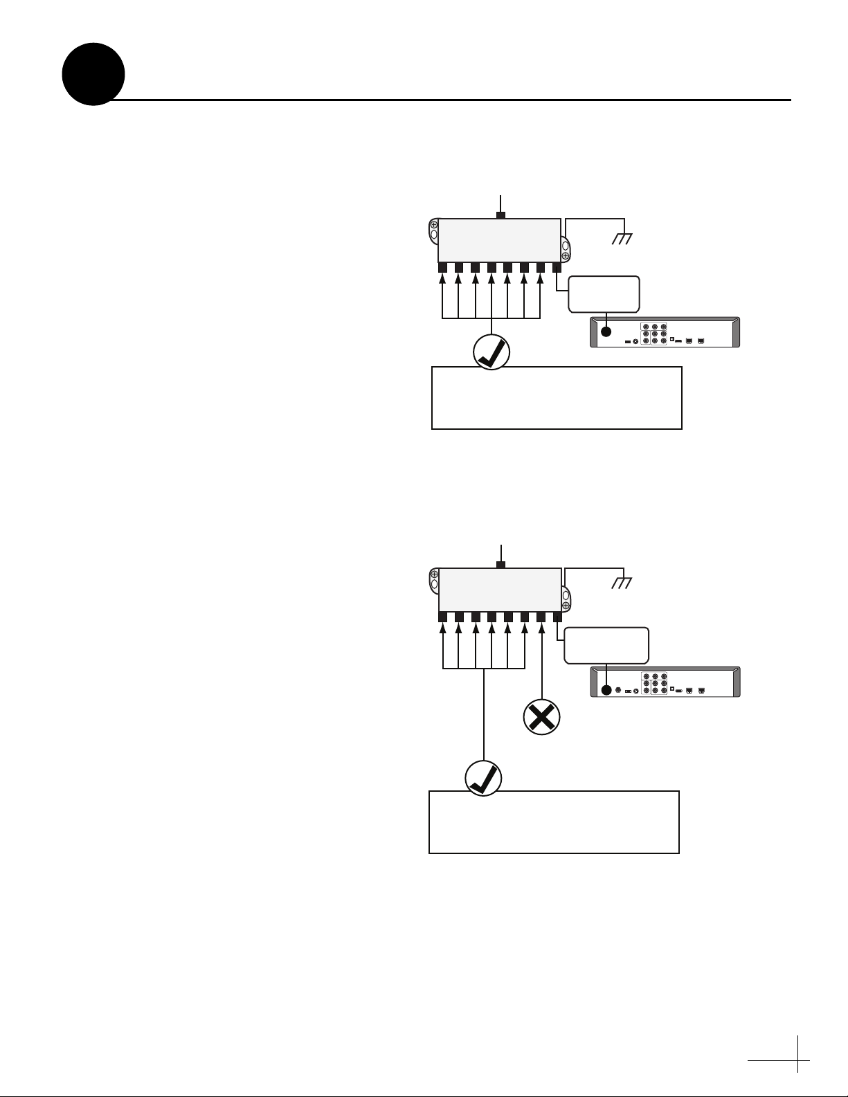
Connect Receivers/DVRs to the Splitter
Now you need to connect the receivers and/or
DVRs to the splitter. Consider the following
connection guidelines before you begin:
• Refer to the basic wiring diagrams in
Figure 23 and Figure 24.
• Since the 8-way splitter supports up to 8
tuners, you can connect any number of SWM
receivers/DVRs that adds up to 8 tuners or
less.
• Each receiver has a single tuner, and requires
one RF cable. Each DVR has two tuners, and
requires one RF cable.
• If you need to connect more than 8 receivers
or 4 DVRs, please contact KVH Technical
Support.
• Connector labeling might vary between
receiver and DVR models. Refer to the User’s
Guide for your selected receivers/DVRs for
complete information.
Figure 23 Basic SWM Receiver Wiring Diagram
Figure 24 Basic SWM DVR Wiring Diagram
• Always terminate any unused splitter
connectors with a supplied terminator (see
Figure 22 on page 14).
15
Page 16

If you need to configure DISH Network, Bell
TV, or legacy DIRECTV receivers, refer to
Appendix C on page 33.
IMPORTANT!
12
Configure Each Receiver/DVR
Follow the steps below to start up the TracVision
system and configure each connected DIRECTV
receiver/DVR for TracVision use.
Power On the TracVision System
a. Plug in the power inserter.
b. Press the power button on the front of the
ACU to turn on the TracVision system (see
Figure 25).
c. Wait up to 3 minutes for the Tracking screen
to display on the ACU (see Figure 26). This
indicates system startup is complete.
Figure 25 ACU Power Button
TRACKING SATS
CONTROL UNIT
ANTENNA
POWER
Power
Button
DIRECTV 99/101/103
CHANGE
MENU
®
Figure 26 Tracking Screen
EXIT
ACCEPT
Power On Connected Components
Plug in and turn on any connected receivers,
DVRs, and televisions.
Set Each DIRECTV Receiver/DVR to Dish
Type: Slimline-3
a. Press the Menu button on the receiver’s/
DVR’s remote control to display its menu on
the connected television.
NOTE: Refer to your selected receiver/DVR manual
for specific configuration instructions.
b. At the “Satellite DISH Setup” menu, set the
Dish Type to Slimline-3.
c. Repeat this procedure for each connected
receiver/DVR.
16
Page 17

RS232
Wi-Fi
KVH and TracVision are registered
trademarks of KVH Industries, Inc.
Tested to comply
with FCC Standards
Meets requirements
ANTENNA
ETHERNET
AC INPUT
100-240V~
160W MAX
50/60 HZ
FUSE
3.15A
250V~
FAST ACTING
This device complies with Part 15 of the FCC rules. Operation is subject
to the following two conditions: (1) This device must not cause harmful
interence, and (2) This device must accept any interference received,
including interference that may cause undesired operation.
RISK OF ELECTRIC SHOCK
DO NOT OPEN
CAUTION
Red (+42V)
Black (Gnd)
Not Used
Wht/Gry
Gry/Wht
Wht/Org
Org/Wht
Not Used
Wht/Brn
Brn/Wht
Wht/Blu
Blu/Wht
ETHERNET
Supplied Router
Ethernet Cable
Antenna Control Unit (ACU)
Onboard Network
Wireless Bridge
OR
OR
13
Connect the ACU to the Network
This section details the ACU’s default network
settings, other available options, and methods for
changing settings. When the TracVision system is
connected to the vessel’s onboard network, or
you connect to the TracVision HD7 system using
the supplied router, the following features are
enabled:
• Remote operation of the TracVision HD7
system
• Remote viewing of the system’s status,
including current satellite signal levels,
satellite settings, and other system
information
• TracVision HD7 software updates can be
checked for and installed remotely
Network Connection Options
Figure 27 Connection Options
- Optional
Choose one of the options below to enable a
network connection (see Figure 27).
• Connect the supplied router to the ACU’s
Ethernet port for wireless access (refer to the
next page for details).
• Connect directly to the vessel’s onboard
network using the ACU’s Ethernet port.
• Connect a wireless bridge, such as Linksys
model #WET54G to the ACU’s Ethernet port.
This allows the TracVision HD7 system to
join the vessel’s network using a WiFi
connection.
TIP: The ACU is Bonjour
connected to the vessel’s onboard network, you can use
Bonjour to easily connect to the ACU using a PC on
the same network, without requiring the IP address.
The ACU is displayed in Bonjour as: hd7-<ACU
serial number>. For more information, visit
www.apple.com/support/bonjour.
®
-enabled. Once the ACU is
17
Page 18
Do not connect to the router’s Internet port.
IMPORTANT!
CONTROL UNIT
MENU
CHANGE
ACCEPT
EXIT
ANTENNA
POWER
®
TRACKING SATS
DIRECTV 99/101/103
Choose Yes to view
Ethernet settings
13
Continued
Connect the ACU to the Network
Connecting the Supplied Router
a. Connect an Ethernet cable from the ACU’s
Ethernet port to an Ethernet port on the
supplied router.
b. Restart the TracVision HD7 system. Then
apply power to the router. Then follow the
instructions below to determine the ACU’s IP
address.
NOTE: No router setup is required. However, if
desired, refer to the router’s manual for alternate setup
and configuration settings.
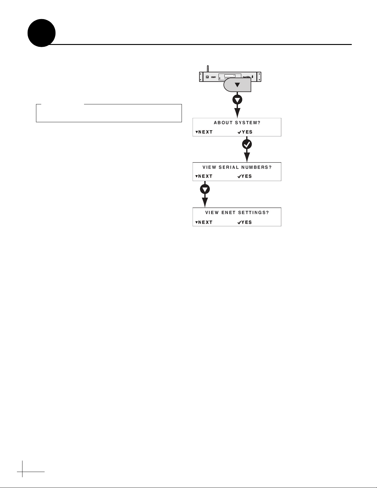
Determining the ACU’s IP Address
You can find the IP address assigned to the ACU
in the View Enet Settings menus (see Figure 28).
Figure 28 Viewing Network Settings on the ACU
Ethernet Settings for Network Integration
Default Settings
The ACU is set up as a DHCP client; the vessel’s
router can automatically assign an IP address
when connected to the ACU’s Ethernet port. In
this case, you will need to connect your PC to the
network, or use an existing PC connected to the
network, to access the ACU’s web interface.
If an IP address is not assigned during startup,
the ACU will assign its own static IP address to
the Ethernet port. This allows you to easily
connect your PC directly to the ACU’s Ethernet
port.
Alternate Settings
If there is no Ethernet network onboard the
vessel, and/or no DHCP server is on the
network, the ACU will assign itself an IP address
that begins with 169 (i.e. 169.x.x.x). In this case,
you can connect your PC directly to the ACU’s
Ethernet port. If your PC is configured for
automatic IP assignment by default, it should
also assign a similar IP address on the same IP
network.
18
Page 19

Enter the ACU’s IP Adress Here
admin
password
Login Information
Current
Settings
Select to Edit
13
Continued Connect the ACU to the Network
Changing Network Settings
Choose one of the methods below if you need to
change network settings:
• Option A - Use the Web Interface
(Recommended)
• Option B - Use the ACU Buttons
Option A - Use the Web Interface (Recommended)
Follow the instructions below to use the web
browser on your PC to change network settings.
NOTE: If you have difficulty accessing the web
interface, you might need to adjust your PC’s
connection settings. Refer to Appendix A on page 25
for more information.
a. Using a PC connected to the vessel’s network,
open the web browser.
Figure 29 Entering the IP Address (Example)
Figure 30 Web Interface Login Screen
b. Enter the ACU’s IP address into the web
browser’s address bar (Figure 29).
c. Log in to the web interface using the
username and password below (see
Figure 30).
username: admin
password: password
d. Select the Settings tab. Then choose Edit to
modify the desired network settings (see
Figure 31).
Figure 31 Network Settings on the Web Interface
19
Page 20
13
Continued Connect the ACU to the Network
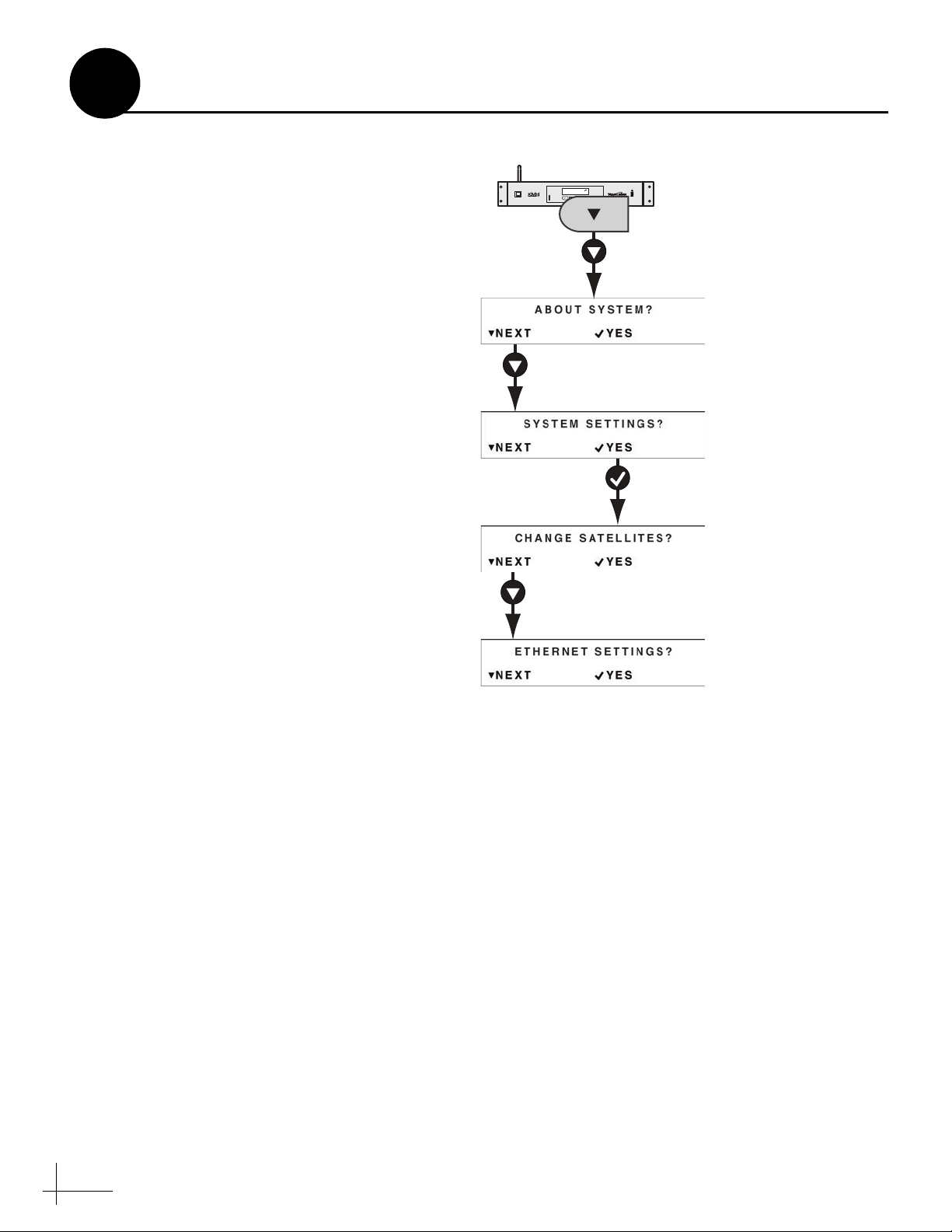
Option B - Use the ACU Buttons
Use the flowchart in Figure 32 to access the
Ethernet Settings menu and change the desired
network settings.
Figure 32 Network Settings Menus
TRACKING SATS
DIRECTV 99/101/103
®
CONTROL UNIT
CHANGE
EXIT
ACCEPT
MENU
ANTENNA
POWER
Choose Yes to
change Ethernet
settings
20
Page 21

Check for Updates
14
Update the Software if Necessary
Choose one of the following options to check for
and install software updates.
NOTE: Checking for updates requires Internet access.
TIP: You can view the ACU’s current IP address, and
other Ethernet settings at any time using the ACU
buttons (see Figure 28 on page 18).
Option A - Use the Web Interface
a. Enter the ACU’s IP address into the address
bar of your web browser (see Figure 29 on
page 19).
b. Log in to the web interface using the
username and password shown in Figure 30
on page 19. Then select Login.
c. Select Check for Updates (see Figure 33).
Then follow the onscreen instructions to
check for and install available software
updates.
Option B - Use a USB Flash Drive
Figure 33 Check for Updates on Web Interface
Figure 34 USB Port on ACU
TRACKING SATS
CONTROL UNIT
ANTENNA
POWER
DIRECTV 99/101/103
CHANGE
ACCEPT
MENU
EXIT
USB Port
®
Note: Software updates (.kvh or .os files) must
be located in the USB flash drive’s root
directory. Be sure to keep only one of each file
type on the flash drive.
If you already have new software saved on a USB
flash drive, use the ACU’s power button to
restart the ACU. Then just plug the flash drive
into the USB port and follow the ACU’s onscreen
instructions to update the software (see
Figure 34) .
Option C - Use the TracVision iPhone® App
If you have the KVH TracVision iPhone/iPod
touch application loaded and configured for use
with the network, follow the app’s onscreen
instructions to check for and install new
software.
TIP: You can download the TracVision iPhone app for
free from the Apple iTunes
®
app store.
21
Page 22

TracVision
15
Educate the Customer
Before you leave the vessel, test the system to
ensure the antenna works properly. Then give
the Customer Welcome Kit to the customer and
explain how to use the system. Ensure the
customer understands the following:
• Keep the radome installed on the antenna at
all times.
• The antenna must have a clear view of the
Southern sky to receive satellite TV. Common
causes of blockage include bridges and boat
masts.
• Heavy rain or snow might temporarily
interrupt reception.
• Clean the radome regularly. Dirt buildup can
affect reception.
• The vessel must be located within the
satellites’ coverage area to receive satellite TV
signals. To view satellite coverage
information, visit www.kvh.com/footprint.
Figure 35 Example of Blockage
Figure 36 KVH TracVision iPhone/iPod touch App
• Please register the system with KVH. The
registration process is quick, easy, online, and
ensures the best possible service from KVH.
Visit www.kvh.com/register or refer to the
Product Registration Form for details.
• You need to activate any connected
receivers/DVRs for the desired satellite TV
service before you can watch television. KVH
can help activate a DIRECTV or DISH
receiver/DVR; just call KVH’s Activation
Department at 1-866-551-8004 for DIRECTV
or 1-866-399-8509 for DISH Network.
• Refer to the supplied TracVision HD7 User’s
Guide for operation instructions and
troubleshooting information.
• You can use the KVH TracVision iPhone/
iPod touch app to communicate with the
TracVision system, as long as it is connected
to the vessel’s onboard network. You can
download the app for free at the Apple
iTunes store.
22
Page 23

Appendices
This section provides additional information on receiver compatibility, receiver setup, and
custom wiring instructions.
Contents
A. Connecting a PC to the ACU .....................................................................25
B. Wiring Non-SWM Receivers......................................................................29
C. Configuring Non-SWM Receivers ............................................................33
D. ACU Menu Structure..................................................................................37
23
Page 24

RS232
Wi-Fi
KVH and TracVision are registered
trademarks of KVH Industries, Inc.
Tested to comply
with FCC Standards
Meets requirements
ANTENNA
ETHERNET
AC INPUT
100-240V~
160W MAX
50/60 HZ
FUSE
3.15A
250V~
FAST ACTING
This device complies with Part 15 of the FCC rules. Operation is subject
to the following two conditions: (1) This device must not cause harmful
interence, and (2) This device must accept any interference received,
including interference that may cause undesired operation.
RISK OF ELECTRIC SHOCK
DO NOT OPEN
CAUTION
Red (+42V)
Black (Gnd)
Not Used
Wht/Gry
Gry/Wht
Wht/Org
Org/Wht
Not Used
Wht/Brn
Brn/Wht
Wht/Blu
Blu/Wht
ETHERNET
A
Connecting a PC to the ACU
This section describes how to connect a PC
directly to the ACU using the supplied Ethernet
cable.
Step 1 - Restart the TracVision System
a. Press the power button on the front of the
ACU to turn off the TracVision system (see
Figure 37).
b. Make sure nothing is connected to the ACU’s
Ethernet port (see Figure 39).
c. Wait 30 seconds. Then press the power
button to turn on the TracVision system.
d. Wait up to 90 seconds for the Tracking screen
to display on the ACU (see Figure 38). This
indicates system startup is complete.
Step 2 - Connect your PC to the Ethernet
Figure 37 ACU Power Button
TRACKING SATS
CONTROL UNIT
ANTENNA
POWER
DIRECTV 99/101/103
CHANGE
MENU
®
Power
Button
Figure 38 Tracking Screen
Figure 39 ACU Ethernet Port
EXIT
ACCEPT
Port
Connect one end of the supplied Ethernet cable
to your PC. Then connect the other end to the
ACU’s Ethernet port (see Figure 39).
Step 3 - Check if the PC Self-Configured for
Communication with the ACU
Depending on your PC’s settings, connecting the
PC to the ACU might automatically configure the
PC’s IP address to communicate with the ACU.
Follow the steps below to check if the PC selfconfigured.
a. Open the Run window in your PC’s Start
menu.
b. Type “ipconfig” into the window. Then press
Enter.
c. The PC’s current IP address is displayed
onscreen.
Figure 40 Run Window
25
Page 25

A
Continued Connecting a PC to the ACU
d. Compare the PC’s IP address to the IP
address assigned to the ACU. If the first three
portions of the IP address match, the PC is
configured to communicate with the ACU.
For example, if the PC’s IP address is
169.100.0.1, and the ACU’s IP address is
169.100.0.2, your PC is configured for ACU
communication; skip to “Access the Web
Interface” on page 27.
NOTE: You can view the ACU’s current IP address
and other Ethernet settings using the ACU buttons
(see Figure 28 on page 18).
Step 4 - Configure Your PC Connection
The following instructions explain how to
configure the Ethernet connection to the ACU on
a PC with Windows XP. Specific configuration
instructions might vary.
Figure 41 Connection Properties
Figure 42 TCP/IP Settings
a. Access Network Settings in the Control Panel
(see Figure 41).
b. Right-click the active connection. Then
choose Properties (see Figure 41).
c. Scroll down to TCP/IP Settings and highlight
the selection. Then choose Properties (see
Figure 42).
d. If desired, record the current settings so you
can restore them once you have finished.
e. Choose to manually assign your PC’s IP
address and network settings (see Figure 43).
f. Assign an IP address one digit higher than
the ACU’s IP address. Then click OK (see
Figure 43).
TIP: For example, if the ACU IP address was
169.100.1.1, you would enter 169.100.1.2).
Figure 43 Manually Entering an IP Address
26
Page 26

Enter the ACU’s IP Adress Here
admin
password
Login Information
A
Continued Connecting a PC to the ACU
Access the Web Interface
a. Open your web browser.
b. Type the ACU’s IP address (not the IP
address you just chose for your PC) into the
address bar (see Figure 44).
TIP: You can view the ACU’s current IP address and
other WiFi/Ethernet settings using the ACU buttons
(see Figure 28 on page 18).
c. Log in to the web interface using the
username and password below (see
Figure 45).
username: admin
password: password
Figure 44 Entering the IP Address (Example)
Figure 45 Web Interface Login Screen
27
Page 27

B
The following wiring diagrams illustrate how to
connect non-SWM receivers/DVRs to the
TracVision HD7 system. Non-SWM receivers/
DVRs include Bell TV, DISH Network, and
legacy DIRECTV receivers. SWM-compatible
receivers/DVRs are listed in the table below.
SWM Receiver/DVR Models*
HR20
HR21
HR21 Pro
HR22
HR23
H20
H21
Wiring Non-SWM Receivers
H22
H23
R16
R22
R23
D12
D13
*NOTE: Additional SWM-compatible receiver and
DVR models might become available at any time. If
your receiver or DVR model is not listed here, check
the receiver’s/DVR’s manual to see if it is SWMcompatible. If your DIRECTV receiver/DVR is not
SWM-compatible, use the wiring diagrams in this
section.
29
Page 28

SWM
Power
Inserter
SWM
SWM
(RF1)
Not Used
Receiver #4
TV SET
OUT
8VSB
TV/ANTENNA/
CABLE IN
SATELLITE IN
13/18V
150mA
S-VIDEO
DIGITAL AUDIO
OUTPUT
R AUDIO VIDEO
PHONE
USB
ETHERNET
L
Pr Pb Y
TV SET
OUT
8VSB
TV/ANTENNA/
CABLE IN
SATELLITE IN
13/18V
150mA
S-VIDEO
DIGITAL AUDIO
OUTPUT
R AUDIO VIDEO
PHONE
USB
ETHERNET
L
Pr Pb Y
Satellite In
Receiver #3
TV SET
OUT
8VSB
TV/ANTENNA/
CABLE IN
SATELLITE IN
13/18V
150mA
S-VIDEO
DIGITAL AUDIO
OUTPUT
R AUDIO VIDEO
PHONE
USB
ETHERNET
L
Pr Pb Y
TV SET
OUT
8VSB
TV/ANTENNA/
CABLE IN
SATELLITE IN
13/18V
150mA
S-VIDEO
DIGITAL AUDIO
OUTPUT
R AUDIO VIDEO
PHONE
USB
ETHERNET
L
Pr Pb Y
Satellite In
Receiver #2
TV SET
OUT
8VSB
TV/ANTENNA/
CABLE IN
SATELLITE IN
13/18V
150mA
S-VIDEO
DIGITAL AUDIO
OUTPUT
R AUDIO VIDEO
PHONE
USB
ETHERNET
L
Pr Pb Y
TV SET
OUT
8VSB
TV/ANTENNA/
CABLE IN
SATELLITE IN
13/18V
150mA
S-VIDEO
DIGITAL AUDIO
OUTPUT
R AUDIO VIDEO
PHONE
USB
ETHERNET
L
Pr Pb Y
Satellite In
Receiver #1
TV SET
OUT
8VSB
TV/ANTENNA/
CABLE IN
SATELLITE IN
13/18V
150mA
S-VIDEO
DIGITAL AUDIO
OUTPUT
R AUDIO VIDEO
PHONE
USB
ETHERNET
L
Pr Pb Y
TV SET
OUT
8VSB
TV/ANTENNA/
CABLE IN
SATELLITE IN
13/18V
150mA
S-VIDEO
DIGITAL AUDIO
OUTPUT
R AUDIO VIDEO
PHONE
USB
ETHERNET
L
Pr Pb Y
Satellite In
Not Used
13V
SAT
Rx4
ANT
IN
Rx3
DC
20V
Rx2
Rx1
18V
SAT
Multiswitch
18V
SAT
13V
SAT
Rx1
Rx2 Rx3
Rx4
Power
Data
ACU
CONTROL UNIT
MENU
CHANGE
ACCEPT
EXIT
ANTENNA
POWER
®
TRACKING SATS
DIRECTV 99/101/103
RF2 RF3
Antenna
Power
Supply
B
Continued Wiring Non-SWM Receivers
Wiring Up to 4 Non-SWM Receivers
NOTE: The supplied SWM power inserter, shown
above, is required, since it supplies power to the
antenna’s LNB.
30
Page 29

SWM
Power
Inserter
SWM
SWM
(RF1)
Not Used
OK to connect up to
7 additional receivers
Receiver #1
TV SET
OUT
8VSB
TV/ANTENNA/
CABLE IN
SATELLITE IN
13/18V
150mA
S-VIDEO
DIGITAL AUDIO
OUTPUT
R AUDIO VIDEO
PHONE
USB
ETHERNET
L
Pr Pb Y
TV SET
OUT
8VSB
TV/ANTENNA/
CABLE IN
SATELLITE IN
13/18V
150mA
S-VIDEO
DIGITAL AUDIO
OUTPUT
R AUDIO VIDEO
PHONE
USB
ETHERNET
L
Pr Pb Y
Satellite In
Power
Data
ACU
CONTROL UNIT
MENU
CHANGE
ACCEPT
EXIT
ANTENNA
POWER
®
TRACKING SATS
DIRECTV 99/101/103
RF2 RF3
Antenna
Splitter
Input
INPUT
OUT OUT
Out Out
Splitter
Input
INPUT
OUT OUT
Out Out
Multiswitch
Power
Supply
Sat A
18V
Sat A
13V
Sat B
13V
Sat B
18V
Not Used
Rx1
Rx8Rx2
Rx7Rx3
Rx6Rx4
Rx5
B
Continued Wiring Non-SWM Receivers
Wiring Up to 8 Non-SWM Receivers*
*NOTE: If desired, you can connect up to 16 receivers
using this wiring diagram and a 16-output
multiswitch.
NOTE: The supplied SWM power inserter, shown
above, is required, since it supplies power to the
antenna’s LNB.
31
Page 30

Enter the ACU’s IP Adress Here
admin
password
Login Information
Select
to Edit
C
Configuring Non-SWM Receivers
Follow the steps below to set the TracVision HD7
system to use your selected satellite service, and/
or configure the non-SWM receivers for use with
the TracVision HD7 system.
Step 1 - Set the Desired Satellite Service
Follow these steps to set the TracVision HD7
system for the satellite service provider of your
choice.
Option A - Use the Web Interface (Recommended)
Follow the instructions below to use the web
browser on your PC to select the desired satellite
service provider.
a. Open your web browser.
b. Enter the ACU’s IP address into the web
browser’s address bar. Then press Enter (see
Figure 46).
Figure 46 Entering the IP Address (Example)
Figure 47 Web Interface Login Screen
c. Log in to the web interface using the
username and password below (see
Figure 47).
username: admin
password: password
d. Select the Settings tab. Then choose
Advanced Settings (see Figure 48).
e. Select the desired satellite service provider.
Then choose Change Service (see Figure 48).
Figure 48 Advanced Settings
33
Page 31
C
Continued Configuring Non-SWM Receivers
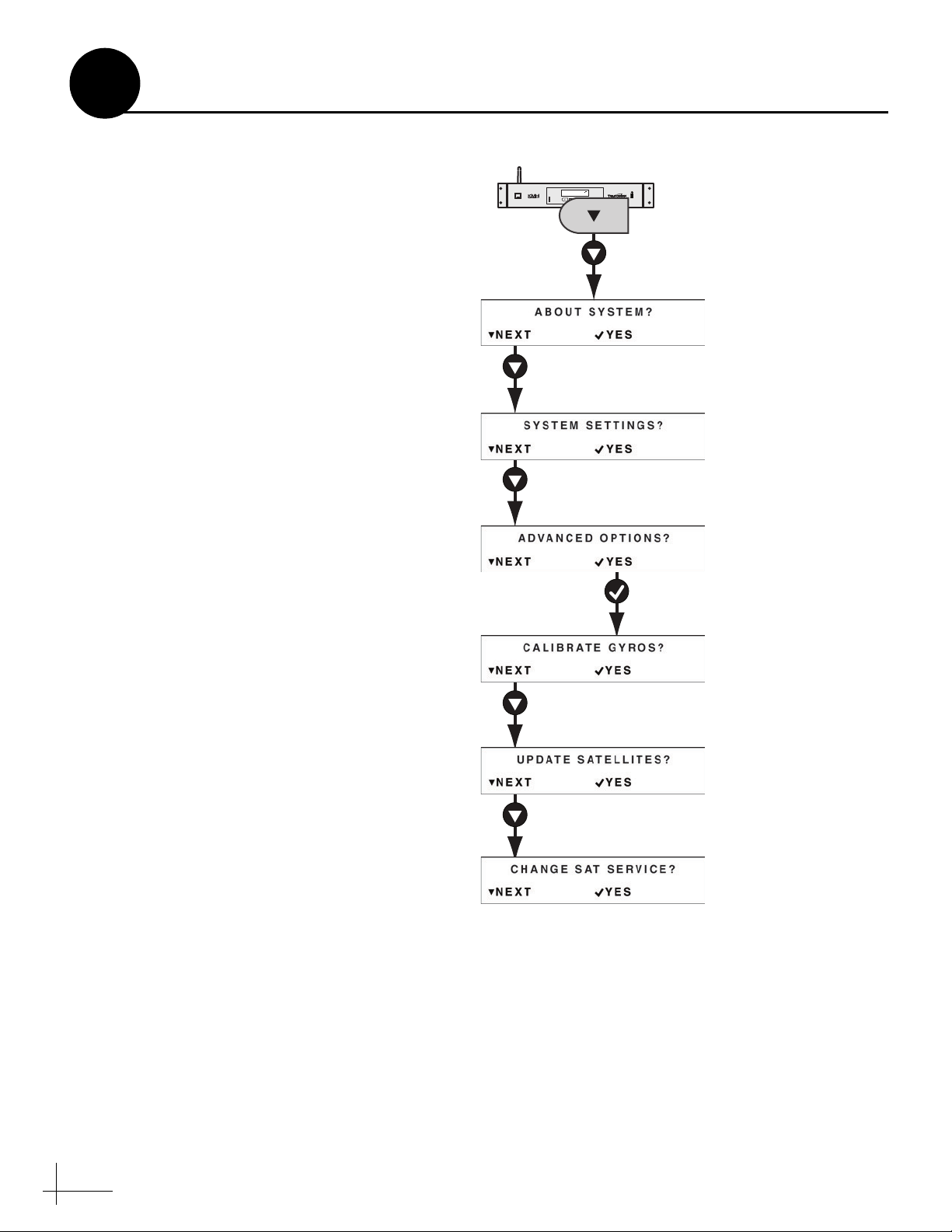
Option B - Use the ACU Buttons
Use the flowchart in Figure 49 to access the
Change Sat Service menu on the ACU. Then
select the desired satellite service provider.
Figure 49 Changing Sat Service Menu
TRACKING SATS
DIRECTV 99/101/103
®
CONTROL UNIT
CHANGE
EXIT
ACCEPT
MENU
ANTENNA
POWER
34
Choose Yes to
change Sat
Service
Page 32

C
Continued Configuring Non-SWM Receivers
Step 2 - Set Up the Receivers
Follow the steps below to configure the nonSWM receivers.
DISH Network/Bell TV Receivers
Follow the steps below to run one Check Switch
test on each connected receiver.
NOTE: Once the receivers are set up, you can switch
satellites as needed using the ACU buttons, web
interface, or TracVision iPhone/iPod touch app.
a. Ensure the antenna has an unobstructed view
of the sky.
b. Using the receiver’s remote control (and a
connected television), go to the “Point Dish/
Signal Strength” screen (press MENU, 6, 1, 1
on most receiver models).
c. Choose Check Switch, then press SELECT.
d. Choose Test, then press SELECT.
e. Wait up to 5 minutes for the test to complete
and the receiver’s Program Guide to load.
TIP: Once complete, the Check Switch displays the
current satellite, followed by “OK.”
f. Using the receiver’s remote, select the
Program Guide to ensure it has loaded
properly.
Legacy DIRECTV Receivers
Using the receiver’s remote control (and a
connected television), set the “Satellite DISH
Type” to “Round.”
35
Page 33

CONTROL UNIT
MENUS
CHANGE
ACCEPT
EXIT
ANTENNA
POWER
®
TRACKING SATS
DIRECTV 99-101-103
ACU
YESNEXT
ABOUT SYSTEM?
YESNEXT
ADVANCED OPTIONS?
YESNEXT
SYSTEM SETTINGS?
Yes
View Software Versions
•
Application
•
Operating System
Yes
View Input Voltages
•
Antenna VDC
•
ACU VDC
Yes
View Ethernet Settings:
• State
•
IP Address
•
Gateway
•
Subnet Mask
MENUS
Yes
YesNext
Next
Next
Yes
Modify Satellite Parameters
for a Selected Satellite/
Polarization:
•
Frequency
•
Symbol Rate
•
FEC Code: Auto, 1-2,
3-4, 5-6, or 7-8
•
Network ID
Yes
Set the Satellite Service
Provider: Bell TV, DIRECTV,
DISH Network, or DIRECTV
Latin America
Yes
Reset to Factory Defaults
•
Satellite Parameters
•
Network Settings
Yes
Modify Ethernet Settings:
•
State: DHCP, Static, or
Disabled
•
IP Address
•
Gateway
•
Subnet Mask
Yes
Modify LCD Screen
Brightness: Low, Medium, or
High
Yes Yes
Next Next
VIEW ENET SETTINGS?
VIEW SOFTWARE INFO?
VIEW POWER INPUT?
View Serial Numbers
•
Antenna
•
ACU
YesNext
Next
Select Among Satellites for
the Selected Service:
•
Bell TV: 82 or 91
•
DIRECTV: 99-101-103 or
101
•
DISH Network: 61, 77,
110 , 119 , o r 129
YesNext
Next
Next
Recalibrates Antenna Gyros
VIEW SERIAL NUMBERS? CHANGE SATELLITES? CALIBRATE GYROS?
UPDATE SATELLITES?
ETHERNET SETTINGS?
ADJUST BRIGHTNESS?
RESET TO DEFAULTS?
CHANGE SAT SERVICE?
D
ACU Menu Structure
37
Page 34

KVH Industries, Inc.
50 Enterprise Center Middletown, RI 02842-5279 U.S.A.
Phone: +1 401 847-3327 Fax: +1 401 849-0045
E-mail: info@kvh.com Internet: www.kvh.com
© Copyright 2009 KVH Industries Inc. KVH, TracVision, and TracPhone are registered trademarks of KVH Industries Inc.
Kokkedal Industripark 2B 2980 Kokkedal Denmark
Phone: +45 45 160 180 Fax: +45 45 160 181
E-mail: info@kvh.dk Internet: www.kvh.com
KVH Europe A/S
 Loading...