

Page 1

TracVision A7
Installation Guide
Page 2
1
TracVision A7 Installation Guide – ADDENDUM
54-0350 Addendum to Rev. A
TracVision A7 Installation
Guide Addendum
ECO #7719
The following information applies to Revision A of the
TracVision A7 Installation Guide (KVH Part Number 54-0350).
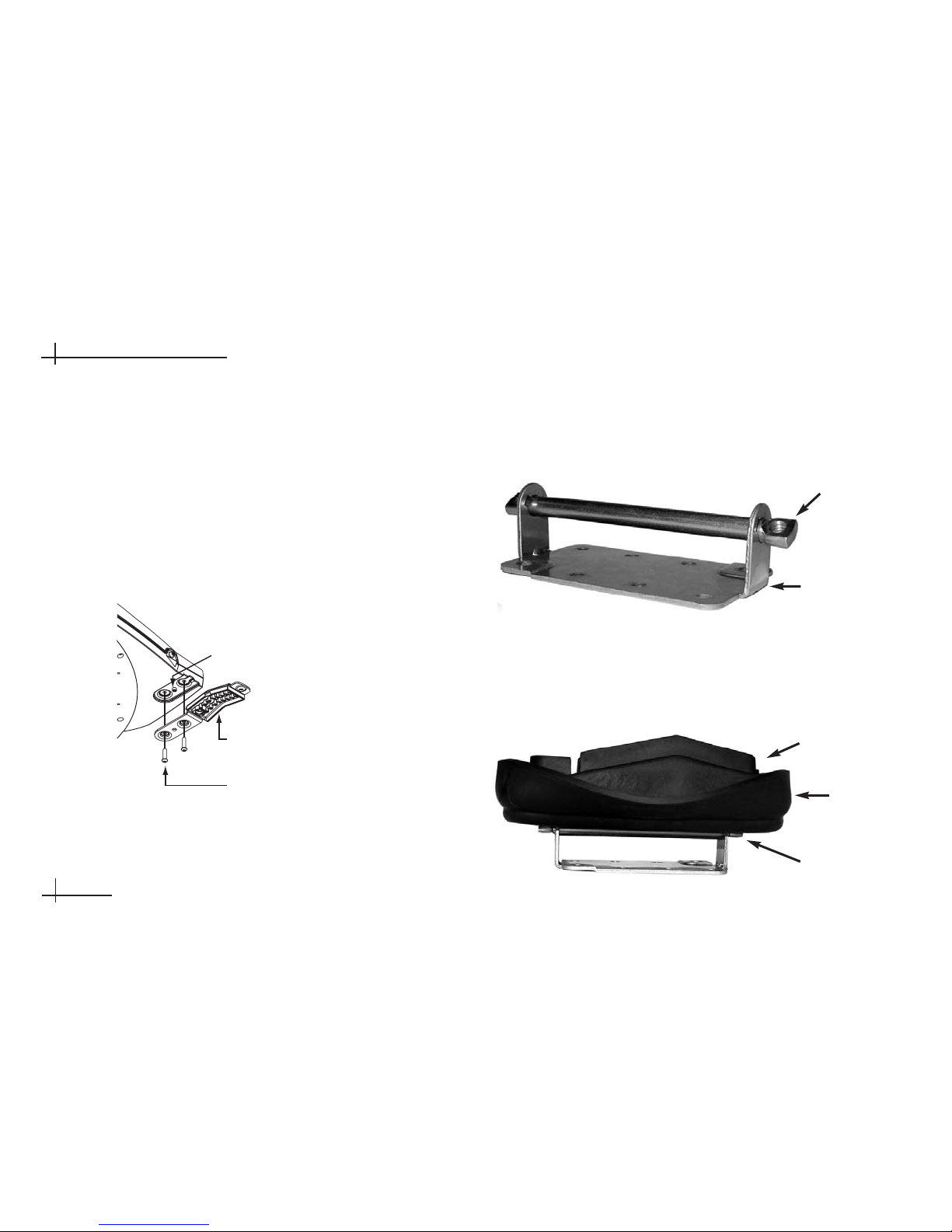
Mounting the Antenna - Roof Mount Kit
The parts and procedure for mounting the TracVision A7 directly
to the roof have changed. This addendum explains this different
procedure.
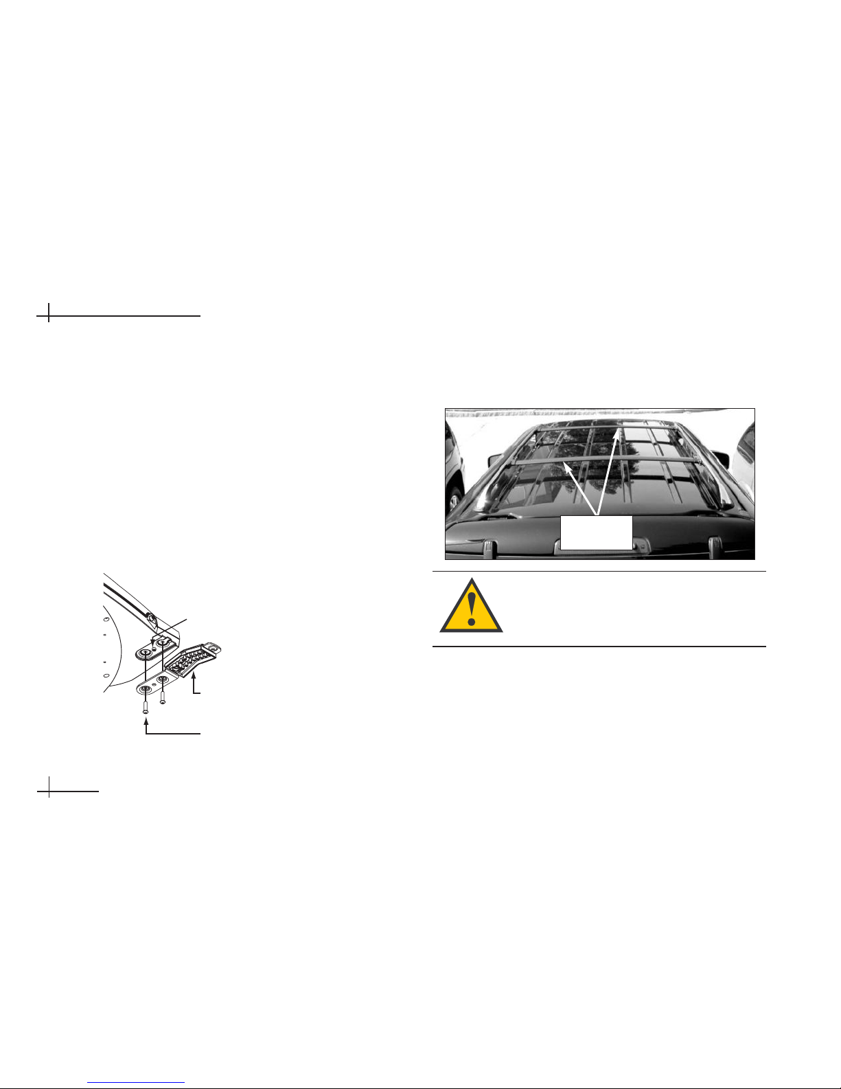
1. With an assistant’s help, position the antenna onto
the center of the vehicle’s roof with a rubber
mounting block under each bracket.
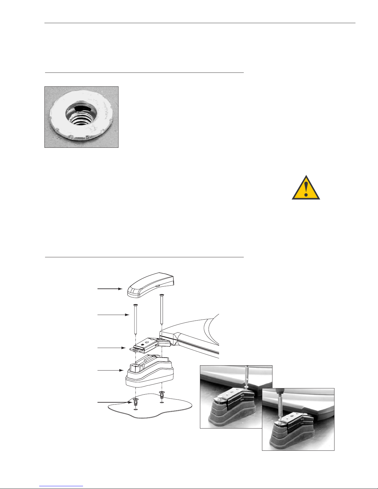
Positioning an Antenna Bracket Onto a Mounting Block
WARNING
PLEASE READ - IMPORTANT!
The roof mount kit is designed for
mounting the antenna to a flat
metal roof up to 3⁄16" thick. It is not
intended to be a universal solution
for all vehicles. Improper use of this
kit, or the use of any other
installation technique, could result
in an unsafe installation and is not
supported by KVH.
Bracket
Mounting Block
Page 3
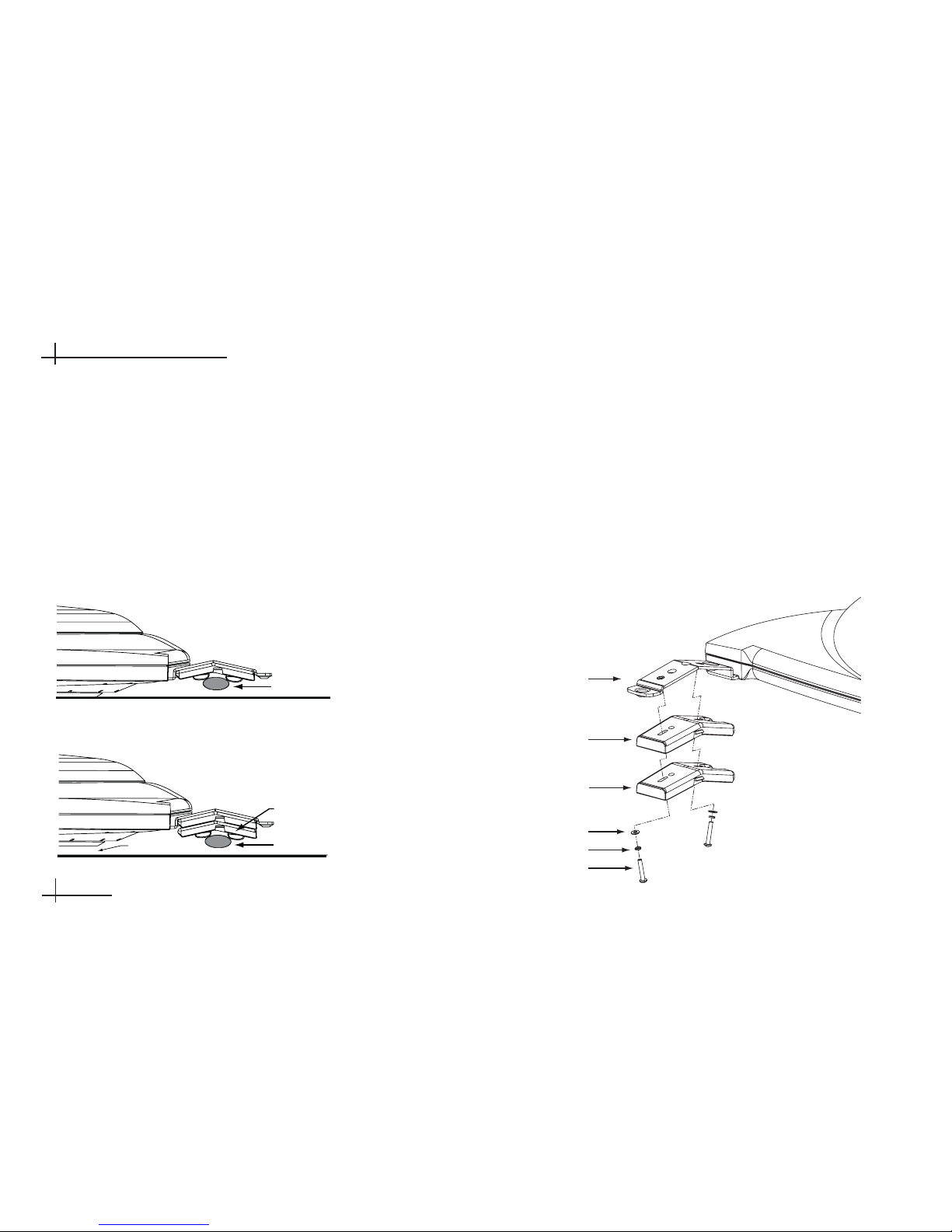
2. The bottom of the antenna should rest a minimum
of 1" above the vehicle’s roof. If the antenna’s base
is less than 1" from the roof, you will need to add a
spacer under each bracket to raise the antenna
higher. If spacers are needed, follow the steps
below to install a spacer under each bracket:
a. Remove the #8-32 x
3
⁄8" screws and washers
securing the factory-installed plastic spacer to
the metal bracket.
b. Insert a second spacer from the kitpack
between the original spacer and the bracket.
Secure both spacers to the bracket using the
#8-32 x 1" screws supplied in the kitpack and
the original washers that you removed in
Step a.
Adding a Second Spacer to the Bracket (If Needed)
2
Bracket
New Spacer
Factory-installed
Spacer
Flat Washer
Lock Washer
#8-32 x 1" Screw
Page 4
c. Place a rubber spacer onto the end of each
rubber mounting block.
Adding a Rubber Spacer to the Mounting Block (If Needed)
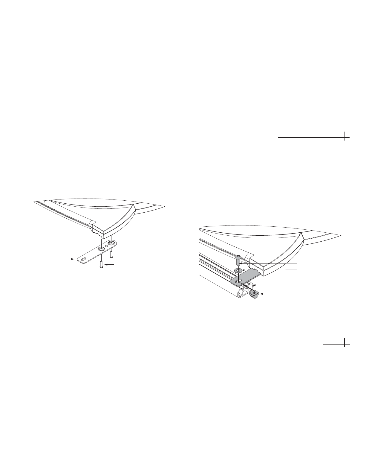
3. With the antenna centered on the vehicle’s roof
and resting on the four mounting blocks, mark the
eight mounting hole locations. To mark the holes,
you can use either a transfer punch or a
21
⁄64" drill
bit as shown below.
Marking the Mounting Holes Using a 21⁄64" Bit
4. Keeping the antenna level at all times, carefully
remove the antenna and mounting blocks from the
vehicle’s roof and set them aside in a safe place.
5. Using a
7
⁄16" drill bit, drill the eight mounting holes
in the vehicle’s roof. Be careful to drill through just
the metal roof, and not through the headliner
beneath it.
3
TracVision A7 Installation Guide – ADDENDUM
54-0350 Addendum to Rev. A
Bracket
Plastic Spacer
Rubber Spacer
Mounting Block
Page 5
6. At each of the eight mounting holes in the roof,
follow the steps below to install a jack nut.
a. Insert the supplied
1
⁄4"-20 x 1" hex head bolt
into a friction wrench, using the large hole
marked “6&8JN.” Be sure to insert the bolt
into the correct side of the wrench (marked
“Enter Screw This Side”). Four friction
wrenches are provided in the kitpack.
Friction Wrench
b. Screw the bolt into a jack nut.
Screwing the Bolt into a Jack Nut
c. Apply silicone sealant or RTV along the
edges of the mounting hole in the roof.
d. Insert the jack nut into the mounting hole.
e. While holding the friction wrench in place,
tighten the bolt with a
7
⁄16" nut driver or socket.
This forces the side tabs of the jack nut to
compress against the underside of the roof. Do
not use an air wrench – it might strip the jack
nut.
4
Jack Nut
If the vehicle’s roof has a thick vinyl
covering, trim the vinyl around each
mounting hole to allow the head of
the jack nut to fully contact the
metal roof.
Page 6
f. Loosen and remove the bolt, leaving the
jack nut secured to the roof.
Jack Nut Secured to Roof
7. Position the mounting blocks back onto the roof,
aligning their holes with the jack nuts.
8. Place the antenna onto the mounting blocks,
aligning the bracket holes with the mounting block
holes.
9. At each mounting hole, insert a
1
⁄4"-20 x 31⁄2" hex
socket screw through the antenna bracket and
mounting block and into the jack nut. Tighten to
secure in place.
Securing the Antenna to the Roof
5
TracVision A7 Installation Guide – ADDENDUM
54-0350 Addendum to Rev. A
WARNING
The mounting screws are prepared
with a thread-locking patch. If these
screws are removed after their
initial installation, the patch’s
locking capacity will be degraded.
Therefore, before reusing the
mounting screws, you MUST apply
threadlocker (Loctite 425) to the
screw threads to avoid a potentially
dangerous condition. Failure to
apply threadlocker to the screw
threads can result in unsecure
mounting.
Cover
Flat-head Screws
Bracket
Mounting Block
Jack Nuts
Page 7
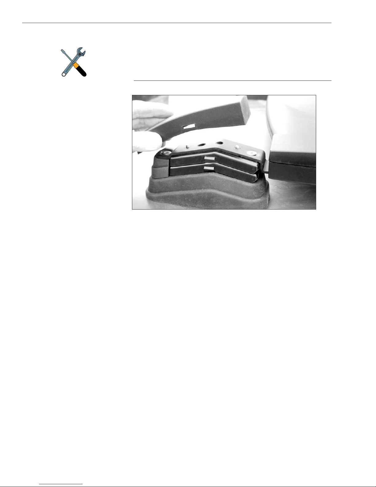
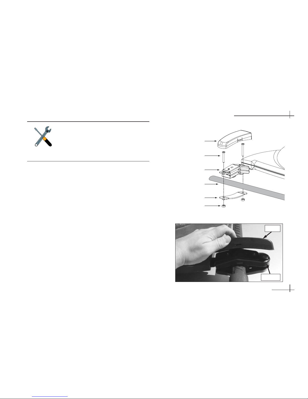
10. Attach a protective cover onto each bracket. The
covers simply snap into place at the sides of the
brackets.
Attaching the Cover
6
Two different sizes of covers are
provided in the kitpack. Install the
two larger covers on the rear
brackets and the smaller covers on
the front brackets.
Page 8
TracVision A7
Installation Guide
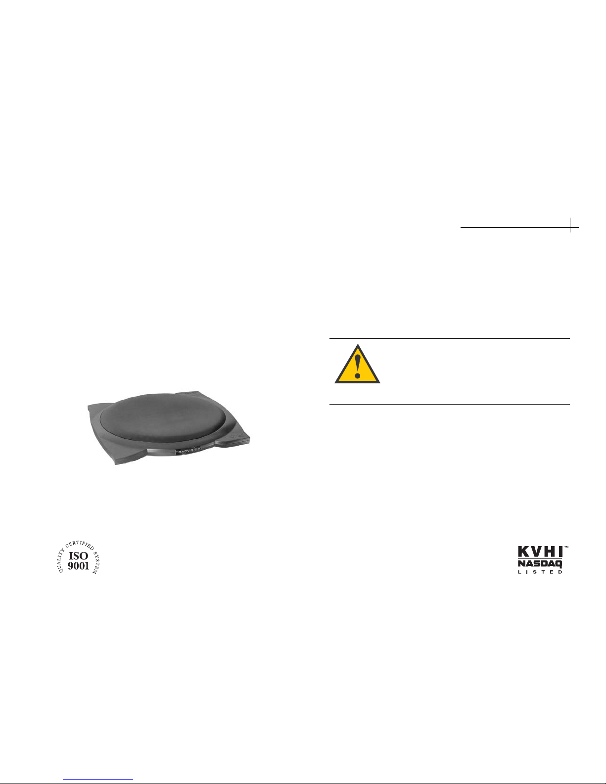
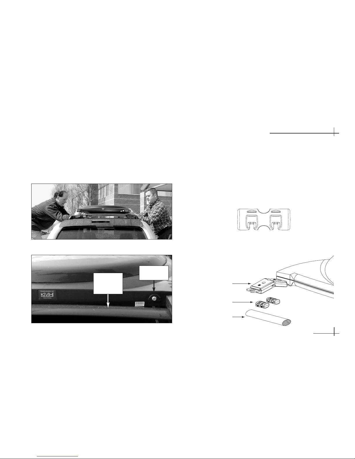
The TracVision A7 is a state-of-the-art, actively
stabilized antenna system that delivers live satellite
TV to a vehicle, even while the vehicle is moving.
This manual provides detailed instructions on the
proper installation of the TracVision A7 system.
Complete instructions on how to use the system are
provided in the User’s Guide and Quick Start Guide.
Welcome Page
This product must NOT be connected to
any active monitor that is visible to the
vehicle’s driver while the vehicle is in
motion. This product is intended for rearseat entertainment only.
KVH Part # 54-0350 Rev. A
© 2006, KVH Industries, Inc., All rights reserved.
Page 9

Trademarks
KVH and TracVision are registered trademarks of KVH Industries, Inc.
Programming, pricing, terms, and conditions are subject to change. Pricing
residential. Taxes not included. Receipt of DIRECTV programming is subject
to the DIRECTV Customer Agreement, a copy of which is provided at
DIRECTV.com/legal and in your first bill.
DIRECTV and the Cyclone Design logo, DIRECTV INTERACTIVE, TOTAL
CHOICE, DIRECTV HOME SERVICES, FREEVIEW, and DIRECT TICKET
are trademarks of DIRECTV, Inc. All trademarks, marks, names, or product
names referenced in this publication are the property of their respective
owners, and KVH neither endorses nor otherwise sponsors any such
products or services referred to herein.
Macrovision Information – Macrovision is a registered trademark of
Macrovision Corporation. This device incorporates an anticopy process
technology that is protected by U.S. patents 4,631,603; 4,577,216; 4,819,098;
and other intellectual property rights. The anticopy process is licensed for
noncommercial, home use only. Reverse engineering or disassembly is
prohibited.
StarSight Information – StarSight features licensed under one or more of the
following patents: 4,706,121; 5,151,789; 5,353,121; 5,353,277; 5,479,266;
5,479,268; and 5,532,754. Use rights reserved.
TruSurround Information – TruSurround and the symbol are trademarks
of SRS Labs, Inc. TruSurround technology is incorporated under license from
SRS Labs, Inc.
ENERGYSTAR Information – ENERGYSTAR and the ENERGYSTAR
certification mark are registered U.S. marks.
TiVo is a registered trademark of TiVo Inc., or its subsidiaries.
Software contained in the TracVision receiver and referenced in this manual
is copyright ©1995-2006 by DIRECTV, Inc. Some features are patent
pending. WatchWizard, PreSelect, TurboTune, and OneLine Guide are
trademarks of Hughes Network Systems. “NFL,” the NFL Shield, and “NFL
SUNDAY TICKET” are registered trademarks of the National Football League
and its affiliates. “NHL,” the NHL Shield, and “NHL CENTER ICE” are
registered trademarks of the National Hockey League. “MLB,” “MLB EXTRA
INNINGS,” “Major League Baseball,” and the Major League Baseball
silhouetted batter logo are service marks of Major League Baseball
Properties, Inc. Major League Baseball trademarks and copyright are used
with permission of Major League Baseball Properties, Inc. All other
trademarks and service marks are the property of their respective owners.
Patent Protection
TracVision A7 is protected by EU Design #000050877-0001; US patents
D493,164; 6,856,300; 6,967,619; and 6,977,614. Other patents pending.
Disclaimer
Every effort has been made to ensure the correctness and completeness of
the material in this document. No company shall be liable for errors
contained herein. The information in this document is subject to change
without notice. No warranty of any kind is made with regard to this material.
Note on recording programming
Most television programs and films are copyrighted. This means that
someone has legal rights governing the reproduction and distribution of this
material. In certain circumstances, copyright law may apply to private taping
of copyrighted materials. In most cases, it is permissible to record for your
personal use, as long as you do not sell the material. You must act
responsibly in this area–check into the matter if you are unsure.
Some pay-per-view programs may be licensed from producers as “view-only”
programs. These are copyrighted programs, and may not be copied or
reproduced for any purpose without the express written permission of the
copyright owner.
54-0350
ii
TracVision A7 Installation Guide
Page 10
54-0350
iii
Important Safety Instructions
Important Safety Instructions
-
Please Read
For your safety and protection, please read this entire
Installation Guide before you install the TracVision
system.
Heed Cautions – Be sure to follow all cautions on the
product and in the installation instructions. Cautions
are indicated by a or icon.
Follow Instructions – Be sure to follow all installation
instructions as detailed in this manual.
The following caution appears on the back of the
receiver:
Do not open the receiver’s cover. Opening or
removing the cover may expose you to dangerous
voltage.
To reduce the risk of fire or
electrical shock, do NOT expose the
receiver to rain or moisture and do
NOT insert any objects into the
receiver’s ventilation openings.
Avoid Driver Distraction
It is dangerous to watch television
or operate the remote control while
you are driving a vehicle. The
TracVision A7 is designed
specifically to provide entertainment to vehicle
passengers and should never be connected to
active video screens visible to the vehicle driver
while the vehicle is in motion. Failure by the
driver of a vehicle equipped with a
TracVision A7 to pay full attention to traffic and
road conditions could result in an accident or
collision with personal injury or death resulting.
WARNING!
CAUTION
CAUTION
Page 11

iv
TracVision A7 Installation Guide
Technical Support
If you need technical assistance when installing the
TracVision A7, please call KVH Technical Support:
Phone:
1-401-847-3327
E-mail: techs@kvh.com
Activation Department
Once the TracVision A7 system is installed, the user
needs to activate the receiver by calling KVH’s
Activation Department:
Phone: 1-866-551-8004
(24 hours a day, 7 days a week)
Send Us Your Comments About This Manual
If you have any comments regarding this manual,
please e-mail them to manuals@kvh.com. Your
feedback is greatly appreciated!
Page 12

54-0350
v
Table of Contents
Table of Contents
1 Getting Started . . . . . . . . . . . . . . . . . .1.1
1-1 Using this Manual . . . . . . . . . . . . . . . .1.3
1-2 System Overview . . . . . . . . . . . . . . . .1.4
1-3 Inspect Parts and Get Tools . . . . . . . .1.6
1-4 Prepare the Activation Card . . . . . . . .1.7
2 Installing the Antenna . . . . . . . . . . . . .2.1
2-1 Remove the Shipping Restraints . . . . .2.3
2-2 Mount the Antenna -
Rack Mount Kit . . . . . . . . . . . . . . . . . .2.4
2-3 Mount the Antenna -
Roof Mount Kit . . . . . . . . . . . . . . . . . .2.8
2-4 Mount the Antenna -
Hummer Mount Kit . . . . . . . . . . . . . .2.12
2-5 Connect the Antenna Cable . . . . . . .2.16
3 Installing the Receiver . . . . . . . . . . . . .3.1
3-1 Choose the Receiver Location . . . . . .3.3
3-2 Wire the Receiver . . . . . . . . . . . . . . . .3.3
3-3 Mount the Receiver . . . . . . . . . . . . . .3.10
3-4 Install Batteries in the Remote . . . . .3.10
4 Completing the Installation . . . . . . . . .4.1
4-1 Post-installation Checklist . . . . . . . . . .4.3
4-2 Test the System . . . . . . . . . . . . . . . . .4.5
4-3 Educate the Customer . . . . . . . . . . . .4.7
Appendices
A System Specifications . . . . . . . . . . . . .A.3
Page 13

54-0350
1.1
Getting Started
1 Getting Started
This section provides a basic overview of this manual and the
TracVision A7 system. It also lists the items you will need to
complete the installation.
Contents
1-1 Using this Manual . . . . . . . . . . . . . . . . . . . . . . . . . . . . .1.3
1-2 System Overview . . . . . . . . . . . . . . . . . . . . . . . . . . . . . .1.4
1-3 Inspect Parts and Get Tools . . . . . . . . . . . . . . . . . . . . . .1.6
1-4 Prepare the Activation Card . . . . . . . . . . . . . . . . . . . . . .1.7
Page 14
1-1 Using this Manual
This manual provides complete instructions for
installing the TracVision A7 system. Throughout this
manual, important information is marked for your
attention by the following icons:
Related Documentation
The following additional documents are provided
with the TracVision A7 system:
Document Description
Receiver User’s Guide Complete operation, setup, and
troubleshooting information
Quick Start Guide Handy quick reference to basic
operation
Product Registration Form Details on registering the
product with KVH
Warranty Statement Warranty terms and conditions
Contents List List of every supplied part
Activation Card Information the owner needs to
activate the receiver
54-0350
1.3
Getting Started
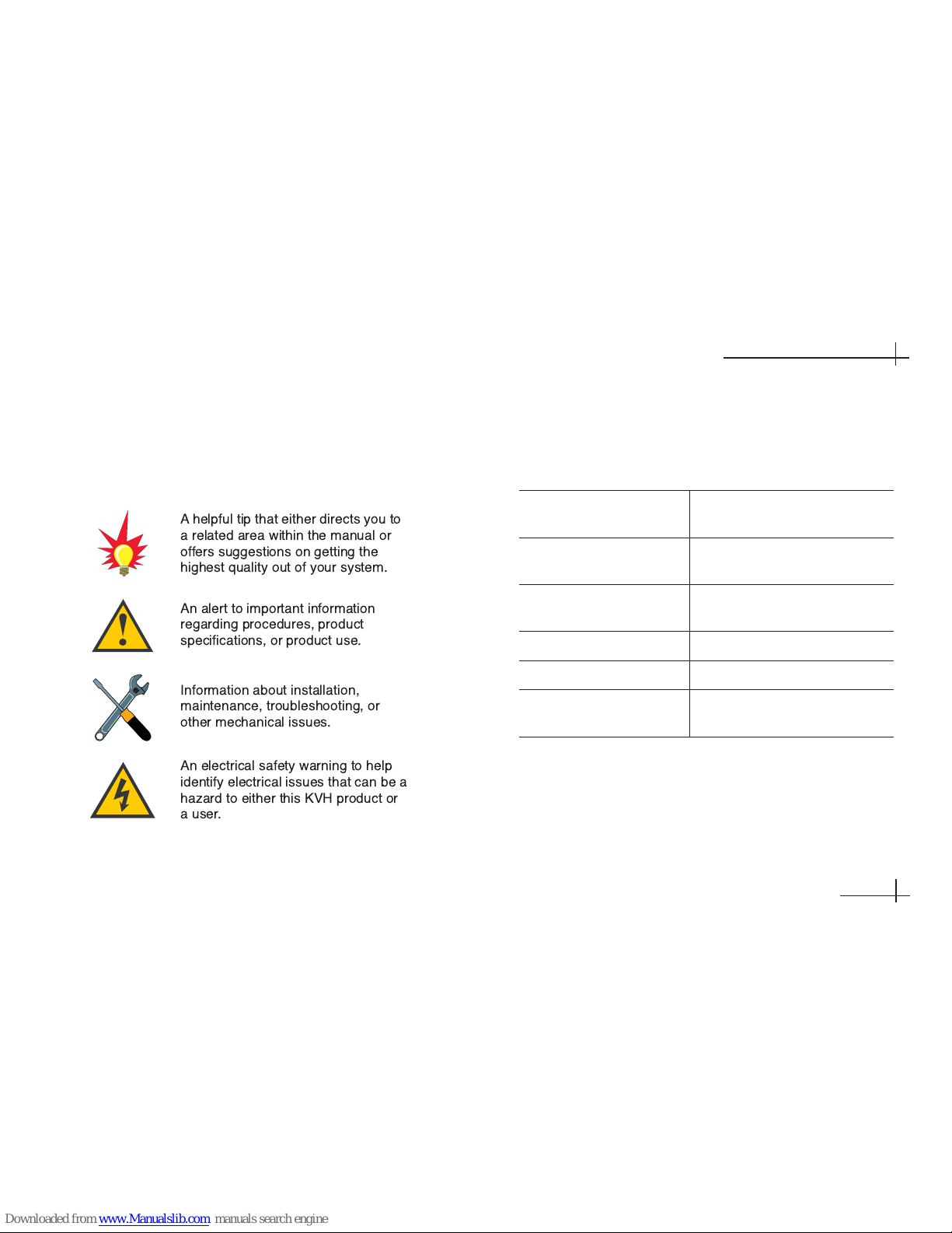
A helpful tip that either directs you to
a related area within the manual or
offers suggestions on getting the
highest quality out of your system.
An alert to important information
regarding procedures, product
specifications, or product use.
An electrical safety warning to help
identify electrical issues that can be a
hazard to either this KVH product or
a user.
Information about installation,
maintenance, troubleshooting, or
other mechanical issues.
Page 15

Who Should Install the TracVision A7 System
KVH strongly recommends that a KVH-authorized
technician and an assistant install the TracVision A7
system. Installers should have experience installing
electronic equipment on a vehicle and have
knowledge about satellite television.
1-2 System Overview
A complete satellite TV system includes the
TracVision A7 antenna and receiver connected to the
vehicle’s audio/video entertainment system. The
remote control and RF (radio frequency) converter
allow the user to operate the system from anywhere
in the vehicle.
54-0350
1.4
TracVision A7 Installation Guide
Vehicle
Mobile Video Display(s)
TracVision A7 Antenna
Purchased Separately
Receiver
Remote Control
C
H
V
O
L
D
V
DV
C
R
A
U
X
T
V
S
A
T
H
R
M
C
9
GUIDE
M
E
N
U
IN
F
O
C
L
E
A
R
T
U
R
B
O
F
A
V
S
E
L
E
C
T
M
U
T
E
C
H
P
R
E
V
PROG
S
E
A
R
C
H
AUDIO
VIDEO
1
2
3
4
5
6
7
8
9
0
INPUT
R
E
W
P
L
A
Y
F
F
R
E
C
S
T
O
P
P
A
US
E
P
A
G
E
O
N
E
L
I
N
E
G
U
I
D
E
PW
R
D
I
R
E
C
T
O
R
RF Converter
Vehicle Power
(12 VDC, 50 watts max)
TracVision A7 System Diagram (Typical Installation)
KVH is not liable for damage (or related
expenses) caused by improper installation.
Page 16
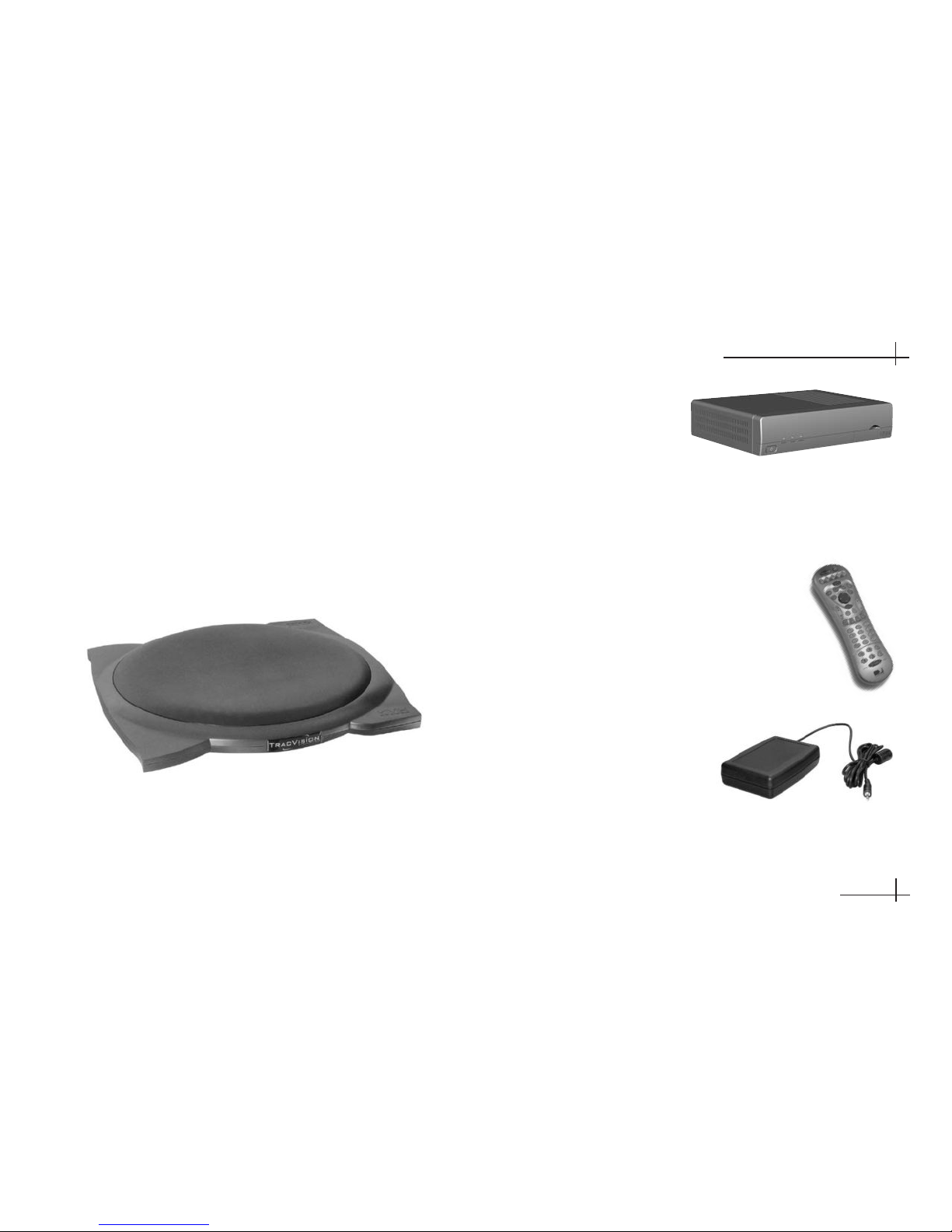
System Components
The TracVision A7 includes the following
components:
Antenna Unit
The antenna unit, mounted on the vehicle’s roof,
houses the phased array, positioning mechanisms,
GPS, low noise block (LNB), and control elements
within a weathertight radome. A single cable
connects the antenna to the receiver inside the
vehicle.
Receiver
The receiver, mounted
inside the vehicle,
decodes satellite
signals from the
antenna unit and sends the signals to the vehicle’s
audio/video system. It also powers and controls the
TracVision antenna.
Remote Control
The backlit wireless RF remote control
allows the user to operate the system
from anywhere in the vehicle. The
remote does not need to be pointed
directly at the receiver for the signal
to be received.
RF Converter
The RF converter receives
RF commands from the
remote control, converts
them to digital signals, and sends them to the receiver
for processing.
54-0350
1.5
Getting Started
Page 17
1-3 Inspect Parts and Get Tools
1. Unpack the box and ensure it contains everything
shown on the antenna and receiver Contents
Lists. Carefully examine all of the supplied parts
to ensure nothing was damaged in shipment.
Save the packaging in case you need to reship the
system.
2. Gather all of the tools and materials listed below.
You will need these items to complete the
installation.
• Hex socket drivers
• Phillips and flat-head
screwdrivers
• Stepladder
•7⁄16" open-end wrench
• Torque wrench
• Wire cutters
• Silicone sealant or RTV
• Measuring tape
If you use the roof mount kit:
• Fasteners suitable for attaching the four metal
mounting plates to the vehicle’s roof
• Pencil or scribe
If you route the antenna cable through the roof:
• Light hammer and center punch
• Drill and 5⁄32" bit
•
1
⁄2" hole saw
If you cut the antenna cable to length:
• LRC/Augat T1000 crimp tool
(KVH P/N 19-0242; call (401) 847-3327 to order)
54-0350
1.6
TracVision A7 Installation Guide
Page 18

1-4 Prepare the Activation Card
Before you install the antenna, peel off the extra serial
number label (taped to the antenna) and affix it in the
appropriate box on the red Activation Card.
54-0350
1.7
Getting Started
Be sure to affix the extra antenna serial
number label to the red Activation Card.
The user will need this number to activate
the receiver, and the receiver must be
activated in order to watch satellite TV via
the TracVision A7 system.
TracVision
®
Activation
Before you can start enjoying satellite TV in your vehicle,
the TracVision receiver must be activated
.
To activate your receiver, please follow the steps below:
1. Call KVH’s Activation Department at:
1-866-551-8004
(24 hours a day, 7 days a week)
You will need to provide the KVH Activation Department
representative with a credit card number and the
following KVH serial numbers:
2. The KVH representative will provide you with 4 ID numbers
necessary for activation. Enter these in the boxes below:
Please save this card for future reference.
You will need these numbers whenever you call DIRECTV.
Installer: Please place antenna
serial number in box above.
54-0208-04, rev. B
Access Card Number
Receiver Serial Number
Antenna Serial Number
Receiver ID Number
DIRECTV Serial Number
Model Number
Activation Card
R
A
Page 19

54-0350
2.1
Installing the Antenna
2 Installing the
Antenna
This section explains how to mount the antenna to the vehicle and
how to connect and route the antenna cable.
Contents
2-1 Remove the Shipping Restraints . . . . . . . . . . . . . . . . . .2.3
2-2 Mount the Antenna - Rack Mount Kit . . . . . . . . . . . . . . .2.4
2-3 Mount the Antenna - Roof Mount Kit . . . . . . . . . . . . . . .2.8
2-4 Mount the Antenna - Hummer Mount Kit . . . . . . . . . . .2.12
2-5 Connect the Antenna Cable . . . . . . . . . . . . . . . . . . . . .2.16
Page 20
2-1 Remove the Shipping Restraints
Cut and remove all of the shipping restraints from
underneath the antenna. To remove the wire
restraints, you will need to use heavy-duty wire
cutters.
54-0350
Installing the Antenna
2.3
1
2
3
4
6
5
Shipping Restraint Locations on Antenna Base
Removing the Shipping Restraints
Page 21
54-0350
2.4
TracVision A7 Installation Guide
2-2 Mount the Antenna -
Rack Mount Kit
If you are mounting the antenna to the vehicle’s roof
rack, follow the steps below. If you are mounting the
antenna directly to the roof, skip to page 2.8. If you
are mounting to a Hummer rack, skip to page 2.12.
1. Attach each of the four mounting brackets to the
antenna base using two 1⁄4"-20 x 3⁄4" hex socket
screws. (A bolt is factory-installed in the base between
the bracket holes.)
2. Position the roof rack crossbars 351⁄2" apart,
measured center-to-center. Ensure that the
crossbars are securely fastened to the vehicle.
Be sure the roof rack’s crossbars are
secured in place and are sturdy enough to
support the 48 lb antenna.
Roof Rack Crossbars
Crossbars
351⁄2" apart
Bracket
Factory-installed bolt
1/4"-20 x 3/4" Hex Socket
Screws
(with Nylok patch)
Attaching the Mounting Brackets
Page 22
3. With an assistant’s help, gently place the antenna
onto the roof rack with the cable connector facing
the rear of the vehicle. All four brackets should
rest on top of the roof rack’s crossbars.
54-0350
2.5
Installing the Antenna
4. Each bracket contains several pairs of pegs. These
pegs allow you to place two rubber cushions in
different positions to best fit the vehicle’s style of
crossbars. Try out the various cushion positions
until you find the best fit for your installation. The
more surface area of the cushions pressing against the
crossbar, the better the fit.
Placing the Antenna on the Crossbars
Antenna Connector Facing Rear of Vehicle
Rear
Roof Rack
Crossbar
Bracket
Roof Rack Crossbar
Rubber Cushions
Positioning Rubber Cushions for Best Fit
Rubber Cushion
Cable
Connector
Page 23
54-0350
2.6
TracVision A7 Installation Guide
5. With the cushions installed in the brackets, the
bottom of the antenna should rest above the
vehicle’s roof. If the antenna’s base touches the
roof, you will need to add a spacer under each
bracket to raise the antenna higher off the
crossbars.
If spacers are needed, follow Steps a and b on this
page to install a spacer under each bracket.
a. Remove the #8-32 x 3⁄8" screws and washers
securing the factory-installed plastic spacer to
the metal bracket.
b. Insert a second spacer from the kitpack
between the original spacer (which holds the
rubber cushions) and the bracket. Secure both
spacers to the bracket using the #8-32 x 7⁄8"
screws supplied in the kitpack and the
original washers that you removed in Step a.
Vehicle Roof
Crossbar
Using Spacers to Raise the Antenna Above the Roof
Vehicle Roof
New Spacer
Gap
Crossbar
Bracket
New Spacer
Flat Washer
Lock Washer
#8-32 Screw
Factory-installed
Spacer
Adding a Second Spacer to the Bracket (If Needed)
Without Spacer
Antenna Touching Roof
With Spacer
Gap Between Antenna and Roof
Page 24
6. Secure each mounting bracket to the roof rack
with a retaining plate, two hex socket screws, and
two jam nuts, as shown in the figure. Use a 13⁄4"
screw at the end of each bracket and use a 2"
screw at the base of each bracket. Be sure to use
the supplied hardware. After securing all four
brackets to the crossbars, verify that all cushions
(two within each bracket) are pressed firmly
against the crossbars providing a solid grip.
7. Attach a protective cover onto each clamp. The
covers simply snap into place at the sides of the
brackets. Two different sizes of covers are provided in
the kitpack. Install the two larger covers on the rear
brackets and the smaller covers on the front brackets.
54-0350
2.7
Installing the Antenna
If you installed extra spacers in Step 5, and
the bottom of the antenna still contacts the
roof, KVH recommends that you either use
the roof mount option or replace the roof
rack with an aftermarket model that offers
greater clearance.
Hex Socket Screws
Cover
Roof Rack Crossbar
Retaining Plate
Jam Nuts
Mounting Bracket
2"
1.75"
Securing the Brackets to the Crossbars
Attaching the Cover
Cover
Bracket
Proceed to Section 2-5 on page 2.16.
Page 25
2. Insert a nut bar into each of the metal mounting
plates so that the nut bar is held suspended
between the mounting plate arms. Ensure the nut
bar swivels easily within the mounting plate.
3. Lift the skirt on the four rubber mounting blocks,
then place the blocks onto the mounting plates.
Align with the threaded holes in the nut bar.
Metal Mounting Plate with Nut Bar
2-3 Mount the Antenna -
Roof Mount Kit
If you are mounting the antenna directly to the roof,
follow the steps below.
1. Attach each of the four mounting brackets to the
antenna base using two 1⁄4"-20 x 3⁄4" hex socket
screws. (A bolt is factory-installed in the base between
the bracket holes.)
54-0350
2.8
TracVision A7 Installation Guide
Bracket
Factory-installed bolt
1/4"-20 x 3/4" Hex Socket
Screws
(with Nylok patch)
Attaching the Mounting Brackets
Rubber Mounting Block Placed onto Mounting Plate
Nut Bar
Mounting
Plate
Mounting
Block
Nut Bar
Skirt
Page 26

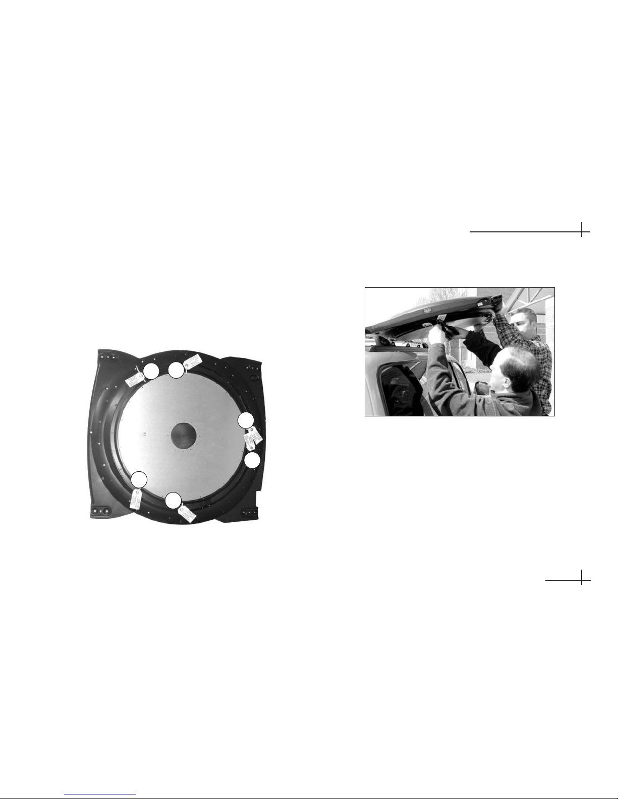
4. With an assistant’s help, position the antenna
onto the centerline of the vehicle’s roof with a
mounting block and mounting plate under each
bracket. Make sure the antenna’s connector faces
the rear of the vehicle.
5. The bottom of the antenna should rest above the
vehicle’s roof. If the antenna’s base is touching
the roof, you will need to add a spacer under
each bracket to raise the antenna higher. If
spacers are needed, STOP the installation.
Call KVH at 401-847-3327 to order the Spacers
Kit (P/N 72-0221). Spacer installation
instructions are provided on page 2.10.
6. Make sure the antenna is positioned on the
centerline of the roof in the desired location and
resting firmly on the mounting blocks. With the
antenna in place, mark the roof along the outside
edges of the mounting plates using a pencil or
scribe.
7. Set aside the antenna and the mounting blocks.
8. Attach the four mounting plates to the roof at the
locations you outlined in Step 6. Be sure to use
fasteners appropriate to the roof’s construction.
9. Seal all fasteners with silicone sealant or
equivalent.
10. Place the rubber mounting blocks back onto the
mounting plates.
11. Place the antenna onto the mounting blocks.
Align the holes in the antenna brackets with the
holes in the mounting blocks.
54-0350
Installing the Antenna
2.9
Bracket
Mounting Block
Positioning an Antenna Bracket Onto a Mounting Block
Due to the variation in RV roof construction,
consult with the RV manufacturer to
determine the safest fastening method.
Page 27

54-0350
2.10
TracVision A7 Installation Guide
Bracket
Plastic Spacer
Rubber Spacer
Mounting Block
Bracket
New Spacer
Flat Washer
Lock Washer
#8-32 Screw
Factory-installed
Spacer
Adding Spacers (If Needed for Extra Height)
Spacer Installation Instructions – If Necessary in Step 5
If spacers are needed to raise the antenna off the
roof, follow the steps below to install a spacer under
each bracket*:
a. Remove the #8-32 x 3⁄8" screws and washers
securing the factory-installed plastic spacer
to the metal bracket.
b. Insert a second spacer from the kitpack
between the original spacer and the bracket.
Secure both spacers to the bracket using the
#8-32 x 7⁄8" screws supplied in the kitpack
and the original washers that you removed
in Step a.
c. Place a rubber spacer onto the end of each
rubber mounting block.
* Requires Spacers Kit (KVH P/N 72-0221).
Page 28

12. At each bracket, insert two of the supplied
1
⁄4"-20 hex socket screws through the antenna
bracket and mounting block and into the
mounting plate’s nut bar. If you added a spacer
as explained on page 2.10, use the 21⁄2" screws
supplied in the Spacers Kit. Otherwise, use the
21⁄4" screws supplied in the roof mount kit.
Tighten the screws to secure in place.
13. Flip down the skirt on each rubber mounting
block to hide the mounting plates.
14. Attach a protective cover onto each bracket. The
covers simply snap into place at the sides of the
brackets.
54-0350
2.11
Installing the Antenna
Mounting Block
Nut Bar
Mounting Plate
Vehicle Roof
Antenna Bracket
Cover
Hex Socket Screws
Securing the Antenna to the Roof
Attaching the Cover
Two different sizes of covers are provided in
the kitpack. Install the two larger covers on
the rear brackets and the smaller covers on
the front brackets.
Proceed to Section 2-5 on page 2.16.
Page 29

2-4 Mount the Antenna -
Hummer
®
Mount Kit
If you are mounting the antenna to a Hummer roof
rack, follow the appropriate steps in this section for
your particular Hummer model:
Hummer H2 . . . . . . . . . . . . . . . . . . . . . .See below
Hummer H3 . . . . . . . . . . . . . . . . . . .See page 2.14
Hummer H2
Mounting Instructions
1. Position the roof rack crossbars 391⁄2" apart,
measured center-to-center. Ensure that the
crossbars are securely fastened to the vehicle.
2. Unlock and remove the end caps from both ends
of the crossbars.
3. Remove the long rubber strips that run along the
top of the crossbars. Be sure to save these strips
for future use.
4. At each crossbar, insert two T-nuts into the center
channel and slide the nuts along the channel.
5. Reinstall the end caps that you removed in Step 2.
54-0350
2.12
TracVision A7 Installation Guide
Be sure the roof rack’s crossbars are
secured in place.
Center Channel
T-nut
Inserting T-nuts in Crossbar Center Channel
Page 30

6. Attach each of the four mounting brackets to the
antenna base using two of the supplied 1⁄4"-20 x 3⁄4"
hex socket screws. Tighten the screws; but do not
overtighten. (A bolt is factory-installed in the base
between the bracket holes.)
7. With an assistant’s help, gently place the antenna
onto the center of the roof rack, with the cable
connector facing the rear of the vehicle. All four
brackets should rest on top of the roof rack’s
crossbars.
54-0350
2.13
Installing the Antenna
8. Position the T-nuts in the crossbars so that they
line up with the holes in the antenna mounting
brackets.
9. At each bracket, place a 3⁄8" flat washer on a
3
⁄8"-16 x 1" hex socket screw and insert the screw
through the bracket’s mounting hole and into the
T-nut in the crossbar. Tighten the screws, but do
not exceed 20 ft-lbf (240 in-lbf) of torque.
Bracket
Factory-installed bolt
1/4"-20 x 3/4" hex socket
screws
(with Nylok patch)
x 2
Attaching Brackets to the Antenna Base
Securing the Antenna Brackets to the Crossbars
Flat Washer
Hex Socket Screw
Crossbar
T- n u t
(in center channel
)
Proceed to Section 2-5 on page 2.16.
Page 31

Hummer H3 Mounting Instructions
1. Position the roof rack crossbars 35" apart,
measured center-to-center. Ensure that the
crossbars are securely fastened to the vehicle.
2. Unlock and remove the end caps from both ends
of the crossbars.
3. Remove the four tie-down anchors from the roof
rack. Save the anchors for future use.
4. Remove the long rubber strips that run along the
top of the crossbars. Be sure to save these strips
for future use.
5. At each crossbar, insert two T-nuts into the center
channel and slide the nuts along the channel.
6. Reinstall the end caps that you removed in Step 2.
54-0350
2.14
TracVision A7 Installation Guide
Roof Rack Tie-down Anchors – Remove
Be sure the roof rack’s crossbars are
seated in the rack’s detents and are locked
in place.
Center Channel
T-nut
Inserting T-nuts in Crossbar Center Channel
Page 32
7. Attach each of the four mounting brackets to the
antenna base using two of the supplied 1⁄4"-20 x 3⁄4"
hex socket screws. Tighten the screws; but do not
overtighten. (A bolt is factory-installed in the base
between the bracket holes.)
8. With an assistant’s help, gently place the antenna
onto the center of the roof rack, with the cable
connector facing the rear of the vehicle. All four
brackets should rest on top of the roof rack’s
crossbars.
9. Position the T-nuts in the crossbars so that they
line up with the holes in the antenna mounting
brackets.
10. At each bracket, place a 3⁄8" flat washer on a
3
⁄8"-16 x 1" hex socket screw and insert the screw
through the bracket’s mounting hole and into the
T-nut in the crossbar. Tighten the screws, but do
not exceed 20 ft-lbf (240 in-lbf) of torque.
54-0350
2.15
Installing the Antenna
Attaching Brackets to the Antenna Base
Bracket
1/4"-20 x 3/4" hex socket
screws
(with Nylok patch
)
Securing the Antenna Brackets to the Crossbars
Flat Washer
Hex Socket Screw
Crossbar
T- n u t
(in center channel)
Page 33
2-5 Connect the Antenna Cable
Now that you have mounted the antenna to the
vehicle’s roof, connect the supplied antenna cable
(see below) to the antenna and route the cable inside
the vehicle.
There are two options for passing the cable into the
vehicle:
Option 1 - Through the roof
Option 2 - Behind the hatch (SUVs and minivans)
If the gap in the vehicle’s hatch hinge is wide enough
when closed to allow the antenna cable to pass
without pinching it, maintaining a 3" bend radius,
you can insert the antenna cable through the gap and
into the vehicle. If the gap is too narrow, you will
need to use the roof drill-through option. Installers
often prefer the professional appearance of the drill-through
option.
Follow the instructions for your selected option:
Through the Roof . . . . . . . . . . . . . . . . .Page 2.17
Behind the Hatch . . . . . . . . . . . . . . . . . .Page 2.20
54-0350
2.16
TracVision A7 Installation Guide
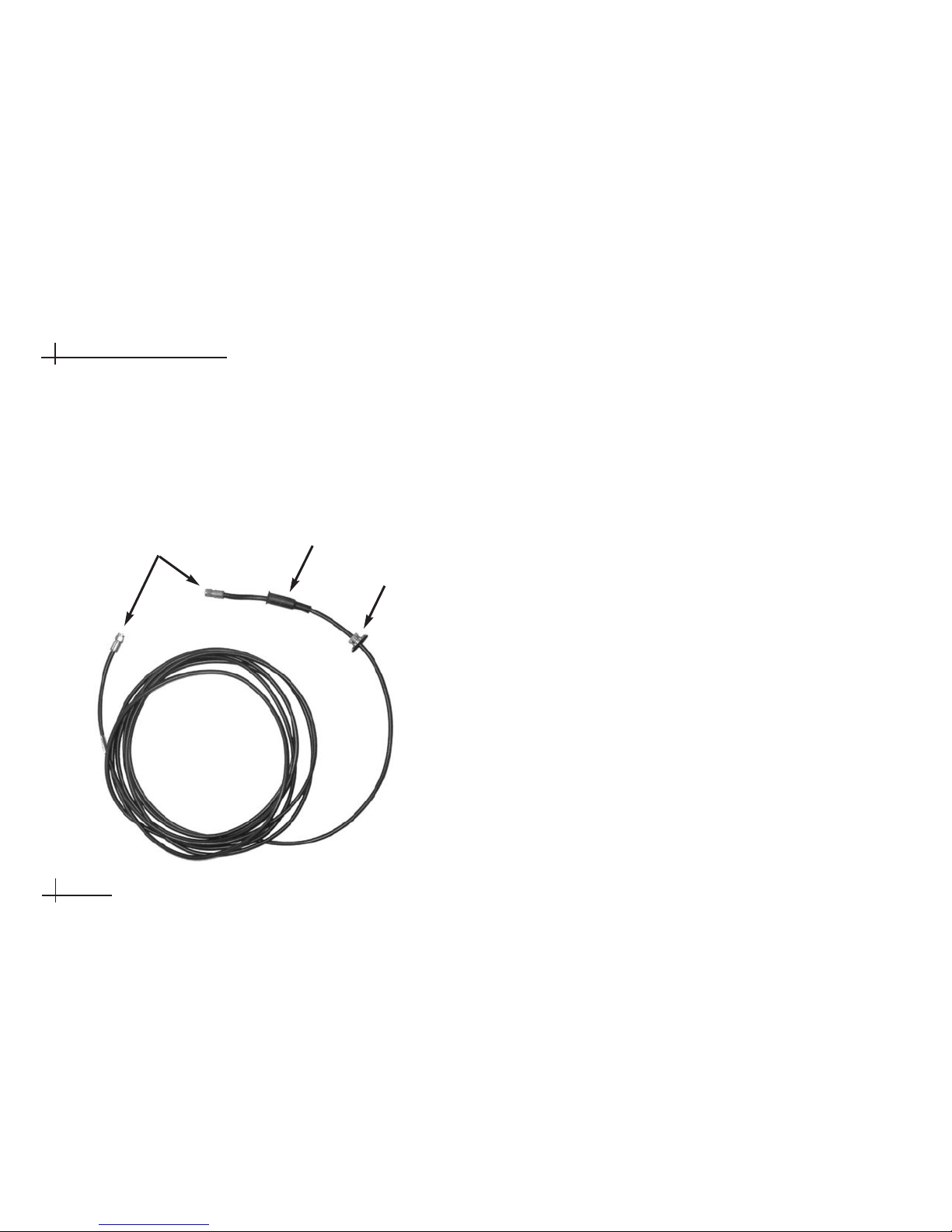
Antenna Cable
Fitting
F-connectors
Rubber Boot
Page 34
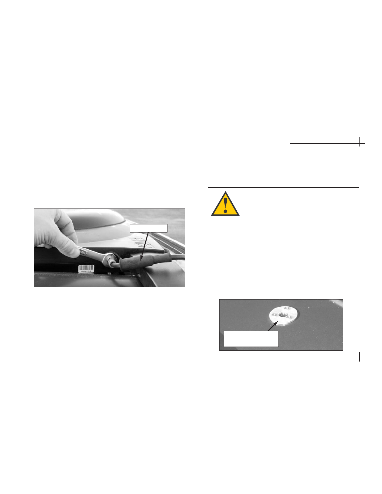
Option 1 - Route the Cable Through the Roof
1. Connect the antenna cable to the antenna. Handtighten, then tighten with a 7⁄16" wrench for 1⁄4 turn
to ensure an electrical and weatherproof
connection.
2. Slide the rubber sealing boot up the cable until it
covers the antenna cable connector. This boot will
help protect the connector from the elements.
3. Choose a location on the roof for the 1⁄2"-diameter
cable access hole. Inside the vehicle, remove the
headliner to access the underside of the roof
where you will be cutting out the hole.
4. Using a 1⁄2" hole saw, cut out the cable access hole
in the vehicle’s roof and smooth the edges of the
hole to protect the cable.
5. Center the backing plate over the cable access
hole to locate the three fitting mounting holes.
Use a center punch to mark the hole locations.
54-0350
2.17
Installing the Antenna
Connecting the Antenna Cable to the Antenna
Rubber Boot
Techniques for removing the headliner vary
from vehicle to vehicle. Only a trained
automotive installer should remove the
headliner. KVH is not liable for damage
caused by improper headliner removal.
Locating the Fitting Mounting Holes
Backing Plate
(used as template)
Page 35
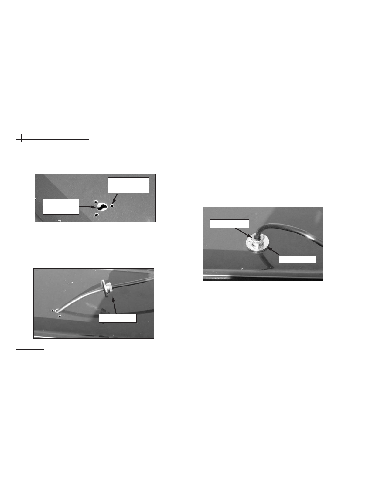
6. Set aside the backing plate, then use a 5⁄32" drill bit
to drill the three fitting mounting holes.
7. Insert the antenna cable into the access hole.
Inside the vehicle, pass the cable through the
backing plate and route the cable to the receiver.
8. Move the fitting down the cable until it covers the
cable access hole, flush to the vehicle’s roof. Line
up the fitting’s three mounting holes with the
three 5⁄32" holes drilled in the roof. Apply silicone
sealant or RTV to the holes and insert the #6-32 x
5
⁄8" screws supplied in the kitpack.
54-0350
2.18
TracVision A7 Installation Guide
1
⁄2" Cable
Access Hole
5
⁄32" Fitting
Mounting Hole
Cable Access Hole and Fitting Mounting Holes
Cable Routed Into Vehicle Through Access Hole
Cable Fitting
Fitting Mounted to Roof
Cable Fitting
Clamping Nut
Page 36
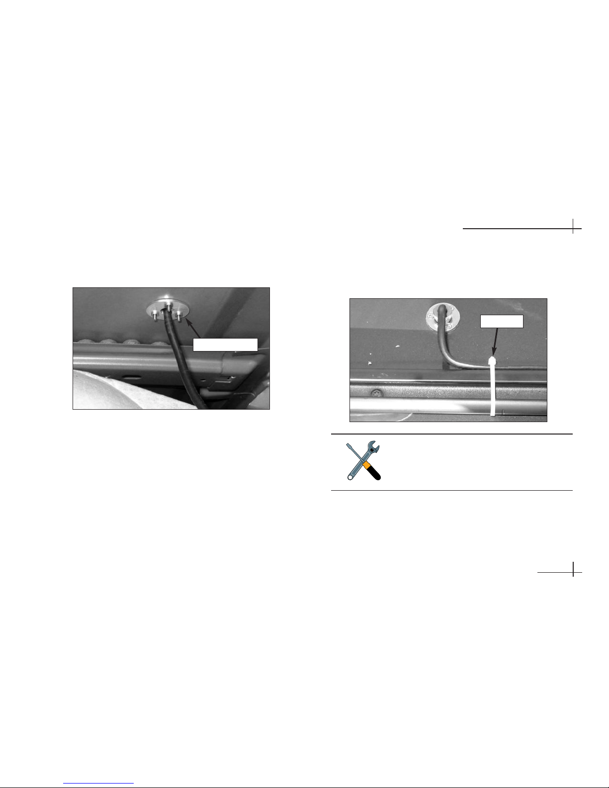
9. Secure the #6-32 x 5⁄8" screws to the backing plate
inside the vehicle.
10. Hand-tighten the fitting’s clamping nut onto the
cable until you’re unable to move the cable back
and forth, ensuring a watertight seal.
11. Using the supplied tie-wraps (or equivalent),
secure the antenna cable to the roof rack, if
necessary.
54-0350
2.19
Installing the Antenna
Backing Plate (Inside Vehicle)
Backing Plate
Securing the Cable to the Roof Rack
Tie-wrap
Do not kink the cable. Maintain a bend
radius of at least three inches. A tighter
bend may disrupt the TV signal and
degrade performance.
Page 37
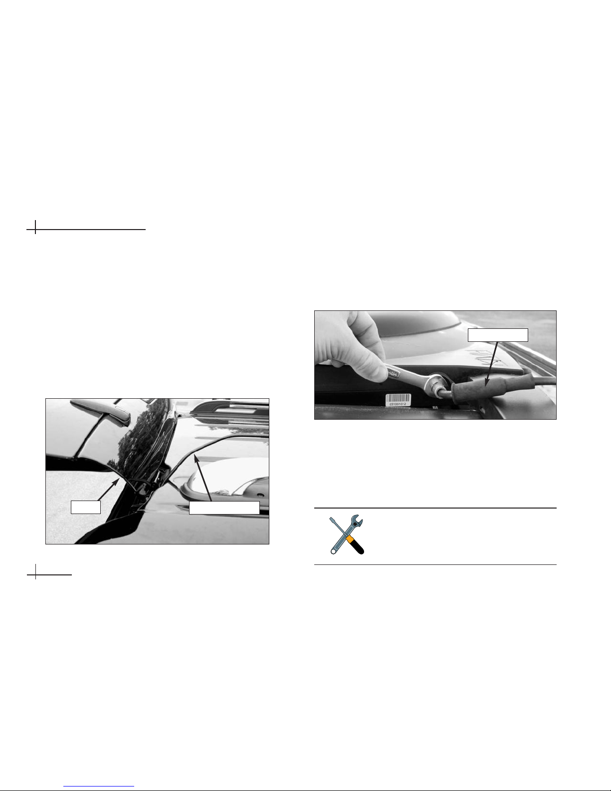
Option 2 - Route the Cable Behind the Hatch
1. Move the steel fitting down the length of the
antenna cable to the end opposite the rubber
boot. You’ll need to connect the end of the cable
with the rubber boot to the antenna. You will not
need to use the fitting; simply keep it attached to the
end of the cable inside the vehicle.
2. Starting from inside the vehicle, pass the antenna
cable through the gap in the hatch hinge.
3. Connect the antenna cable to the antenna. Handtighten, then tighten with a 7⁄16" wrench for 1⁄4 turn
to ensure an electrical and weatherproof
connection.
4. Slide the rubber sealing boot up the cable until it
covers the antenna cable connector. This boot will
help protect the connector from the elements.
5. Using the supplied tie-wraps (or equivalent),
secure the cable to the roof rack, if necessary.
54-0350
2.20
TracVision A7 Installation Guide
Cable Routed Behind Rear Hatch
Antenna Cable
Hatch
Do not kink the cable. Maintain a bend
radius of at least three inches. A tighter
bend may disrupt the TV signal and
degrade performance.
Connecting the Antenna Cable to the Antenna
Rubber Boot
Page 38

54-0350
3.1
Installing the Receiver
3 Installing the
Receiver
This section explains how to connect all system cables to the
mobile receiver and how to mount the receiver inside the vehicle.
Contents
3-1 Choose the Receiver Location . . . . . . . . . . . . . . . . . . . .3.3
3-2 Wire the Receiver . . . . . . . . . . . . . . . . . . . . . . . . . . . . . .3.3
3-3 Mount the Receiver . . . . . . . . . . . . . . . . . . . . . . . . . . .3.10
3-4 Install Batteries in the Remote . . . . . . . . . . . . . . . . . . .3.10
Page 39

54-0350
3.3
Installing the Receiver
3-1 Choose the Receiver Location
Now that you’ve installed the antenna, you need to
find a suitable location inside the vehicle for
installing the receiver. The receiver should be
installed in an area that meets the following
requirements:
• Dry
• Well-ventilated
• Away from heat sources
• Allows enough open space (at least 2" around)
for ventilation and cable connections
3-2 Wire the Receiver
For the TracVision system to work, you will need to
connect the following cables to the receiver:
• Antenna cable
• RF converter cable
• Audio/video (A/V) cables
• DC power cable
The procedures in this section are intended
for a basic wiring configuration. If the
vehicle’s entertainment system is wired
differently, use these procedures as a guide
and connect the cables as needed to suit
the vehicle’s particular configuration.
This section explains how to wire a single
TracVision mobile receiver. For details on
connecting additional receivers, refer to
Appendix A in the TracVision Mobile
Receiver User’s Guide.
Page 40
54-0350
3.4
TracVision A7 Installation Guide
CAUTION
This device complies with Part 15 of the FCC rules. Operation is subject
to the following two conditions: (1) This device must not cause harmful
interference, and (2) This device must accept any interference received,
including interference that may cause undesired operation.
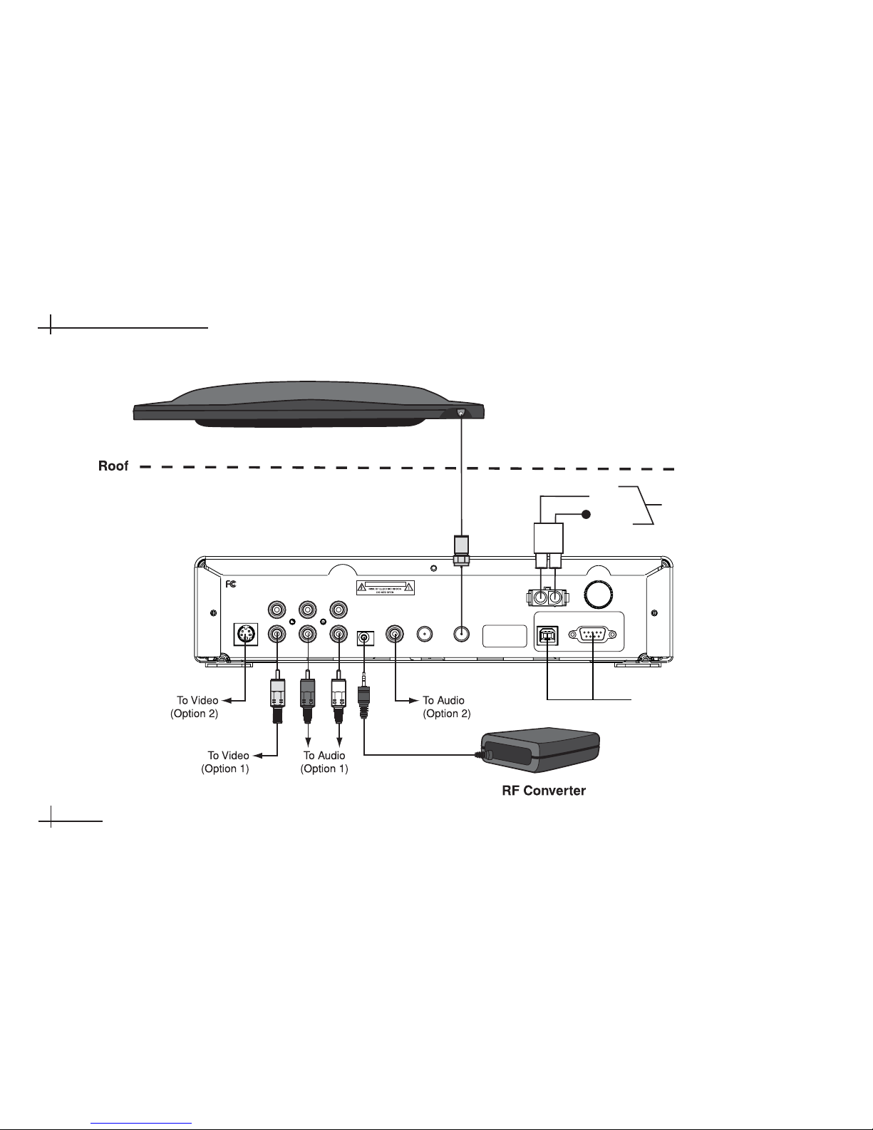
S-VIDEO
VIDEO AUDIO L AUDIO R
RF
REMOTE
INPUT
DIGITAL
AUDIO
OUT
TO
110W/HD
CONVERTER
TO KVH
ANTENNA
POWER (10-16V DC)
MAINTENANCE PORTS
USB
RS232
FUSE (8A)
Tested to comply
with FCC Standards
Receiver
Antenna
Service/
Maintenance
Only
DC Power
Ground
Input Power
(10-16 VDC)
Black
Red
TracVision A7 Wiring Diagram
Page 41

54-0350
3.5
Installing the Receiver
Prepare the Antenna Cable
The antenna cable should already be connected to the
antenna and routed to the receiver. If the cable is too
long, you may either coil the excess cable inside the
vehicle or cut the end of the cable to the desired
length. If you choose to cut the cable, use an LRC/
Augat T1000 crimp/strip tool to attach the supplied
Snap-N-Seal®F-connector to the end of the cable.
Since the antenna cable carries data, power, and
communications, the integrity of this cable and its
connections is very important.
If you do not have an LRC/Augat T1000 tool (KVH P/N
19-0242), please order one from KVH at 401-847-3327.
Connect the Antenna Cable
Connect the antenna cable to the “To KVH Antenna”
jack on the receiver’s rear panel. Screw the connector
down securely.
Do not use a screw-on, push-on, or
twist-on connector. Low-quality connectors
will degrade system performance and
KVH’s warranty does not cover repairs
resulting from the use of such connectors.
Augat Tool
CAUTION
This device complies with Part 15 of the FCC rules. Operation is subject
to the following two conditions: (1) This device must not cause harmful
interference, and (2) This device must accept any interference received,
including interference that may cause undesired operation.
S-VIDEO
VIDEO AUDIO L AUDIO R
RF
REMOTE
INPUT
DIGITAL
AUDIO
OUT
TO
110W/HD
CONVERTER
TO KVH
ANTENNA
POWER (10-16V DC)
MAINTENANCE PORTS
USB
RS232
FUSE (8A)
Tested to comply
with FCC Standards
Antenna
Receiver
Vehicle Roof
Page 42

Connect the RF Converter Cable
To connect the RF converter cable, follow the steps
below.
1. Connect the RF converter cable to the “RF
Remote Input” jack on the receiver’s rear panel.
2. Place the RF converter at least three feet away
from the receiver and other electronic devices.
And do not place the RF converter behind a
metal structure. Otherwise, the remote control
might not operate properly due to interference.
Velcro is provided in the kitpack to mount the RF
converter to a structure inside the vehicle.
54-0350
3.6
TracVision A7 Installation Guide
Connect the Audio/Video Cables
The receiver kit includes standard audio/video cables
with RCA-type connectors for connecting the receiver
to your vehicle’s entertainment system. The receiver
also includes S-Video and digital audio jacks, which
you may use instead. Follow the procedures on the
next page for your desired type of connections.
CAUTION
This device complies with Part 15 of the FCC rules. Operation is subject
to the following two conditions: (1) This device must not cause harmful
interference, and (2) This device must accept any interference received,
including interference that may cause undesired operation.
S-VIDEO
VIDEO AUDIO L AUDIO R
RF
REMOTE
INPUT
DIGITAL
AUDIO
OUT
TO
110W/HD
CONVERTER
TO KVH
ANTENNA
POWER (10-16V DC)
MAINTENANCE PORTS
USB
RS232
FUSE (8A)
Tested to comply
with FCC Standards
Receiver
RF Converter
CAUTION
This device complies with Part 15 of the FCC rules. Operation is subject
to the following two conditions: (1) This device must not cause harmful
interference, and (2) This device must accept any interference received,
including interference that may cause undesired operation.
S-VIDEO
VIDEO AUDIO L AUDIO R
RF
REMOTE
INPUT
DIGITAL
AUDIO
OUT
TO
110W/HD
CONVERTER
TO KVH
ANTENNA
POWER (10-16V DC)
MAINTENANCE PORTS
USB
RS232
FUSE (8A)
Tested to comply
with FCC Standards
Receiver
If the entertainment system has only a
coaxial input available, you will need an RF
modulator (Radio Shack model 15-2526 or
equivalent).
Page 43

Connect the Audio Cables
Option 1 – Standard Audio Cables
(cables included)
Connect the red and white audio cables to the
receiver’s “Audio L” and “Audio R” jacks. The jacks
are color-coded. Connect the other ends to the
entertainment system’s audio inputs. If only one audio
input jack is available, connect the white cable and leave
the red cable disconnected.
Option 2 – Digital Audio Cable
(cable not included)
Connect your digital audio cable to the receiver’s
“Digital Audio Out” jack. Connect the other end to
the entertainment system’s digital audio input.
CAUTION
S-VIDEO
VIDEO AUDIO L AUDIO R
RF
REMOTE
INPUT
DIGITAL
AUDIO
OUT
TO
110W/HD
CONVERTER
TO KVH
ANTENNA
Tested to comply
with FCC Standards
Receiver
54-0350
3.7
Installing the Receiver
Connect the Video Cable
Option 1 – Standard Video Cable
(cable included)
Connect the yellow video cable to the receiver’s
“Video” jack. The jack is color-coded. Connect the
other end to the entertainment system’s video input.
Option 2 – S-Video Cable
(cable not included)
Connect your S-Video cable to the receiver’s
“S-Video” jack. Connect the other end to the
entertainment system’s S-Video input.
CAUTION
S-VIDEO
VIDEO AUDIO L AUDIO R
RF
REMOTE
INPUT
DIGITAL
AUDIO
OUT
TO
110W/HD
CONVERTER
Tested to comply
with FCC Standards
Receiver
Page 44

Connect the Power Cable
Now that you’ve connected all other cables to the
receiver, follow the steps below to connect the power
cable.
1. Remove the key from the ignition and remove the
negative lead from the vehicle’s battery.
2. Connect the receiver power cable’s red (positive)
wire to +12 VDC switched (accessory) power.
With the vehicle running and the receiver turned on,
power at the receiver must measure at least 11 VDC.
3. Connect the receiver power cable’s black
(negative) wire to its own dedicated chassis
ground (such as a pillar ground screw) within 18"
of the receiver. The black wire must make contact
between the metal of the ground screw and the
metal of the vehicle frame.
54-0350
3.8
TracVision A7 Installation Guide
4. Plug the other end of the power cable into the
“Power” jack on the receiver’s rear panel.
5. Reconnect vehicle power.
Before connecting the receiver power cable,
be sure that vehicle power is turned off and
power is disconnected from the circuit.
+12 VDC
Switched Power
(Accessory Power)
Ground
Pillar Ground Screw
CAUTION
This device complies with Part 15 of the FCC rules. Operation is subject
to the following two conditions: (1) This device must not cause harmful
interference, and (2) This device must accept any interference received,
including interference that may cause undesired operation.
AUDIO L AUDIO R
RF
REMOTE
INPUT
DIGITAL
AUDIO
OUT
TO
110W/HD
CONVERTER
TO KVH
ANTENNA
POWER (10-16V DC)
MAINTENANCE PORTS
USB
RS232
FUSE (8A)
Power Wiring (Preferred)
Do not connect the receiver power cable
directly to the vehicle’s battery without
following the special instructions on the
following page.
Page 45

54-0350
3.9
Installing the Receiver
Connect the Power Cable to the Battery
(Alternative Wiring Option, Only If Necessary)
If you are unable to connect the receiver power cable
to switched (accessory) power as described on the
previous page, you may wire the receiver to battery
power if you follow the minimum requirements
listed below.
• Install a protective fuse (6 amps) within 18" of the
battery.
• Install a relay, switched from the ignition,
between the battery and the receiver.
• Use fire-resistant AWG 8 wire from the relay to
the battery.
Ground
Pillar Ground Screw
Fuse
(6 amp)
Vehicle
Battery
+12 VDC
Ground
Switched
Relay
Ground
Ignition
AWG 8
Wire
+–
A
UTION
This device complies with Part 15 of the FCC rules. Operation is subject
to the following two conditions: (1) This device must not cause harmful
interference, and (2) This device must accept any interference received,
including interference that may cause undesired operation.
DIGITAL
AUDIO
OUT
TO
110W/HD
CONVERTER
TO KVH
ANTENNA
POWER (10-16V DC)
MAINTENANCE PORTS
USB
RS232
FUSE (8A)
Power Wiring (Alternative Option)
Bus, Limo, and RV Installations
If vehicle power fluctuates or is noisy, KVH
recommends that you use an AC/DC power
supply (KVH P/N 72-0206-01) to provide
stable power to the receiver.
Page 46

3-3 Mount the Receiver
Once all cables are connected, mount the receiver
inside the vehicle.
1. Using the supplied #2-56 x 1⁄4" screws, attach the
two L-shaped brackets to the sides of the receiver.
2. Using appropriate 1⁄4" fasteners for your
installation, secure the receiver brackets to the
mounting surface.
Mounting the Receiver
Bracket
#2-56 Screws (x3)
1⁄4" Fasteners (x4)
(not supplied)
54-0350
3.10
TracVision A7 Installation Guide
3-4 Install Batteries in the Remote
The receiver comes with an RF/IR remote control.
Insert two AAA batteries in the remote control’s
battery compartment. Be sure to observe the correct
polarity.
Do not block the receiver’s ventilation
openings. These openings ensure reliable
operation of the receiver and protect it from
overheating.
AAA Batteries
Remote Control Batteries
Page 47

54-0350
4.1
4 Completing the
Installation
This section explains how to turn on and test the TracVision A7
system. It also lists important information the owner needs to know.
Contents
4-1 Post-installation Checklist . . . . . . . . . . . . . . . . . . . . . . .4.3
4-2 Test the System . . . . . . . . . . . . . . . . . . . . . . . . . . . . . . .4.5
4-3 Educate the Customer . . . . . . . . . . . . . . . . . . . . . . . . . .4.7
Completing the Installation
Page 48
54-0350
4.3
Completing the Installation
4-1 Post-installation Checklist
Congratulations! You’ve completed the TracVision A7
installation. Before you turn on and test the system,
please make certain that you have completed the
following important steps:
Step Page # Done?
You affixed the antenna serial number label to the red Activation Card
.
1.7
You removed the antenna’s shipping restraints from below. 2.3
You attached the mounting brackets to the antenna using the supplied 2.4, 2.8, 2.13,
hardware. 2.15
Rack or Hummer Mount:
You verified the roof rack crossbars are 2.4, 2.12, 2.14
securely fastened to the vehicle and are sturdy enough for the antenna.
Rack Mount:
You positioned the rubber cushions within the antenna 2.5
mounting brackets to best fit the vehicle’s crossbars.
Rack or Roof Mount:
You allowed enough clearance between the 2.6,2.9
antenna and the roof.
Roof Mount:
You attached the mounting plates to the roof using 2.9
appropriate fasteners and sealed them to prevent leakage.
Hummer Mount:
You inserted the supplied T-nuts into the center channel 2.12, 2.14
of the crossbars.
Page 49
54-0350
4.4
TracVision A7 Installation Guide
Step Page # Done?
You secured the antenna to the vehicle using the supplied hardware. 2.7, 2.11, 2.13
2.15
After connecting the antenna cable to the antenna, you installed 2.17, 2.20
the rubber boot over the connector.
If you routed the antenna cable through the roof, you used the 2.18
supplied fitting and backing plate and sealed the holes.
If you cut the antenna cable, you used an LRC/Augat T1000 tool 3.5
to attach the supplied F-connector to the end of the cable.
You connected the antenna cable to the receiver. 3.5
You connected the RF converter to the receiver and placed it 3.6
3 feet away from the receiver and not behind a metal structure.
You connected high-quality audio/video cables from the receiver to the 3.6
vehicle’s entertainment system.
You connected the receiver’s power cable to +12 VDC switched 3.8
(accessory) power and did not connect other devices to the same circuit.
You mounted the receiver in a dry location away from any heat sources 3.10
and allowed plenty of room for ventilation.
You installed two “AAA” batteries in the remote control. 3.10
Receiver Location:
Page 50
2. Apply vehicle power and turn on the vehicle’s
entertainment system.
3. Turn on the power switch on the front of the
TracVision mobile receiver.
54-0350
4.5
Completing the Installation
4-2 Test the System
Now all you need to do is turn the system on and
ensure everything works properly. Follow the steps
below to turn on the TracVision A7 system and verify
proper operation.
1. Ensure the antenna has a clear view of the
satellite. The antenna requires an unobstructed
view of the southern sky to receive satellite TV
signals. Trees, buildings, highway overpasses,
etc., can block satellite signals. Heavy rain or
snow might also interrupt satellite signals. For
complete details about satellite reception
requirements, refer to Section 1-3, “Receiving
Satellite TV Signals,” in the User’s Guide.
Receiver Power Switch
Since the TracVision antenna requires an
unobstructed view of the southern sky to
receive satellite signals, the system will not
work when the vehicle is in a garage.
Power Switch
Page 51
4. Wait while the antenna searches the sky for the
satellite. Within a few minutes, all three status
lights on the front of the receiver should be lit
green. If any of these lights are not green, refer to
Section 10-4, “System Status Lights,” in the User’s
Guide for troubleshooting details.
5. A progress bar will appear on the TV, indicating
that the receiver is downloading the program
guide. Once the guide is loaded, verify that you
can view the DIRECTV preview channel (100).
54-0350
4.6
TracVision A7 Installation Guide
Installation
If your satellite dish is ready for DIRECTV
®
service, please wait until your
Advanced Program Guide
™
is prepared.
Acquiring guide data...
Receiver Status Lights
Status Lights
Program Guide Load Progress Bar
Only the DIRECTV®preview channels (such
as channels 100 and 201) are viewable until
the owner activates the receiver.
Page 52

4-3 Educate the Customer
Be sure to give the manuals to the owner and explain
how to use the product. The owner also needs to
know the following:
• The antenna must have a clear view of the
southern sky to receive satellite TV. Common
causes of blockage include trees, buildings,
overpasses, and mountains. The TracVision
antenna will not work inside a garage.
• Heavy rain or snow may temporarily interrupt
reception.
• The antenna should be cleaned regularly. Dirt
buildup on the radome can affect reception.
• Make sure the user knows the new height of
his/her vehicle, measured from the road to the
top of the antenna, so that he/she can avoid
parking garages and overpasses that are too low.
• It is dangerous to watch TV while driving a
vehicle. The TracVision system is intended as a
passenger entertainment product.
• The owner needs to register the system for
product warranty validation. Refer to the Product
Registration Form for details or visit:
www.kvh.com/register.
• Refer to the Quick Start Guide and the User’s Guide
for complete operation instructions.
• If the owner removes the antenna from the roof,
then later needs to reinstall it, the owner must
apply threadlocker (Loctite 425) to the threads of
the mounting screws to avoid a potentially
dangerous condition. The mounting screws are
prepared with a thread-locking patch that will
degrade if the screws are removed. Failure to
apply threadlocker to the screws during
reinstallation can result in unsecure mounting.
• Be sure to give the owner the red Activation
Card, which has information required for
activating the mobile receiver. The receiver must
be activated before it can receive satellite TV
programming. To activate, the owner needs to call
KVH’s Activation Department toll-free at
1-866-551-8004 (24 hours a day, 7 days a week).
54-0350
4.7
Completing the Installation
Page 53

54-0350
A.1
System Specifications
Appendix A
System Specifications
Physical Characteristics
Power 10-16 volts DC, 50 watts
Antenna Dimensions 30.5" wide x 5.3" high
Antenna Weight 48 lbs
Receiver Dimensions 11" wide x 9" long x 2.5" high
Receiver Weight 4 lbs
Pointing System
Elevation Range 31º to 57º
Azimuth Range Unlimited
Wind Force 100 mph
Stabilization 2-axis, actively gyro-stabilized
Environmental
Operating Temperature -13ºF to +131ºF (-25ºC to +55ºC)
Storage Temperature -20ºF to +140ºF (-29ºC to +60ºC)
Humidity to 100 percent
Page 54

KVH Industries, Inc. 50 Enterprise Center • Middletown, RI 02842-5279 U.S.A .• Phone: (401) 847-3327 • Fax: (401) 849-0045 • E-mail: info@kvh.com
www.kvh.com
© Copyright 2006, KVH Industries, Inc. KVH®and TracVision®are registered trademarks of KVH Industries, Inc.
 Loading...