

Trac Vac 682-IC, 682-R, 682-H, 682-PRO Operating And Assembly Manual

Model 682-IC/PRO/H/R
Operating and Assembly
Manual
Midwest Equipment Manufacturing, Inc.
5225 Serum Plant Road
Thorntown, IN 46071
06-28-16

SAFETY RULES
Remember, any power equipment can cause injury if operated improperly or if the user does not understand
how to operate the equipment. Exercise caution at all times when using power equipment.
This symbol means Attention!!!!! It is used to point out safety precautions.
▪ Read and follow all instructions in this manual before assembly or operation of this equipment.
Failure to comply with these instructions may result in personal injury. Keep this manual for future
reference and for ordering replacement parts.
▪ Read this instruction manual carefully. Become familiar with the controls and proper use of this
equipment.
▪ Read the engine owners manual and safe operation rules before using this equipment.
▪ Never allow children less than 16 years of age to operate the Trac-Vac. Children 16 years
and older should operate only under close parental supervision.
▪ Do not allow anyone to operate this equipment without proper instruction.
▪ Do not allow passengers to ride on the Trac-Vac or on the towing vehicle.
▪ Keep children and pets out of area of operation.
▪ Check fuel before starting engine. Do Not fill fuel tank indoors, or while engine is running or hot.
Wipe off any spilled fuel before starting engine.
▪ Engine and muffler get HOT! Do Not touch! Keep debris from accumulating on or around engine
and muffler to avoid fire hazard.
▪ Allow engine to cool before storing in any enclosed area. Never store Trac-Vac with fuel in tank.
▪ Do not operate engine if air cleaner or cover is removed, except for adjustments. Removal of the part
could create a fire hazard.
▪ Keep hands, feet, face, long hair and clothing out of inlet and discharge areas. There are ROTATING
BLADES inside these openings.
▪ Make certain that all moving parts come to a complete stop before cleaning, repairing or inspection.
Disconnect spark plug wire and keep away from plug to prevent accidental starting.
▪ If Trac-Vac should become clogged with debris, SHUT OFF ALL ENGINES and wait until impeller
comes to a complete stop before attempting to remove obstruction. Disconnect spark plug wire to
prevent accidental starting.
▪ If excessive vibration occurs while operating your Trac-Vac, stop the engine immediately, disconnect
the spark plug wire and allow all moving parts to stop completely before taking the following steps.
A. Inspect for damage.
B. Repair or replace any damaged parts.
C. Check for loose parts and tighten to assure continued safe operation.
▪ Check all hardware periodically to insure safe operation.
▪ Check cart cover periodically for wear and replace if worn or damaged.
▪ Never operate Trac-Vac without intake hose and exhaust hose attached in proper place.
▪ Do Not remove exhaust hose or attempt to empty contents of container while engine in running.
▪ Keep all shields and guards in place and securely attached.
▪ Always wear eye protection (safety glasses or goggles) when operating this equipment.
▪ Do Not stand behind unit in exhaust discharge area while engine is running.
▪ Do Not operate this equipment while intoxicated or while taking medications that could impair
reactions or senses.
▪ Operate this equipment at reduced ground speed on rough terrain, along creeks and ditches and on
slopes to prevent tipping or loss of control.
▪ Vehicle stability and braking are affected by the addition of this unit. Do not fill the Trac-Vac to its
full capacity without checking the capability of the towing vehicle to safely pull and stop with the unit
attached.
▪ Do Not operate on slopes in excess of 10 degrees. STAY OFF OF STEEP SLOPES!
▪ Follow the maintenance instructions outlined in this manual.
1
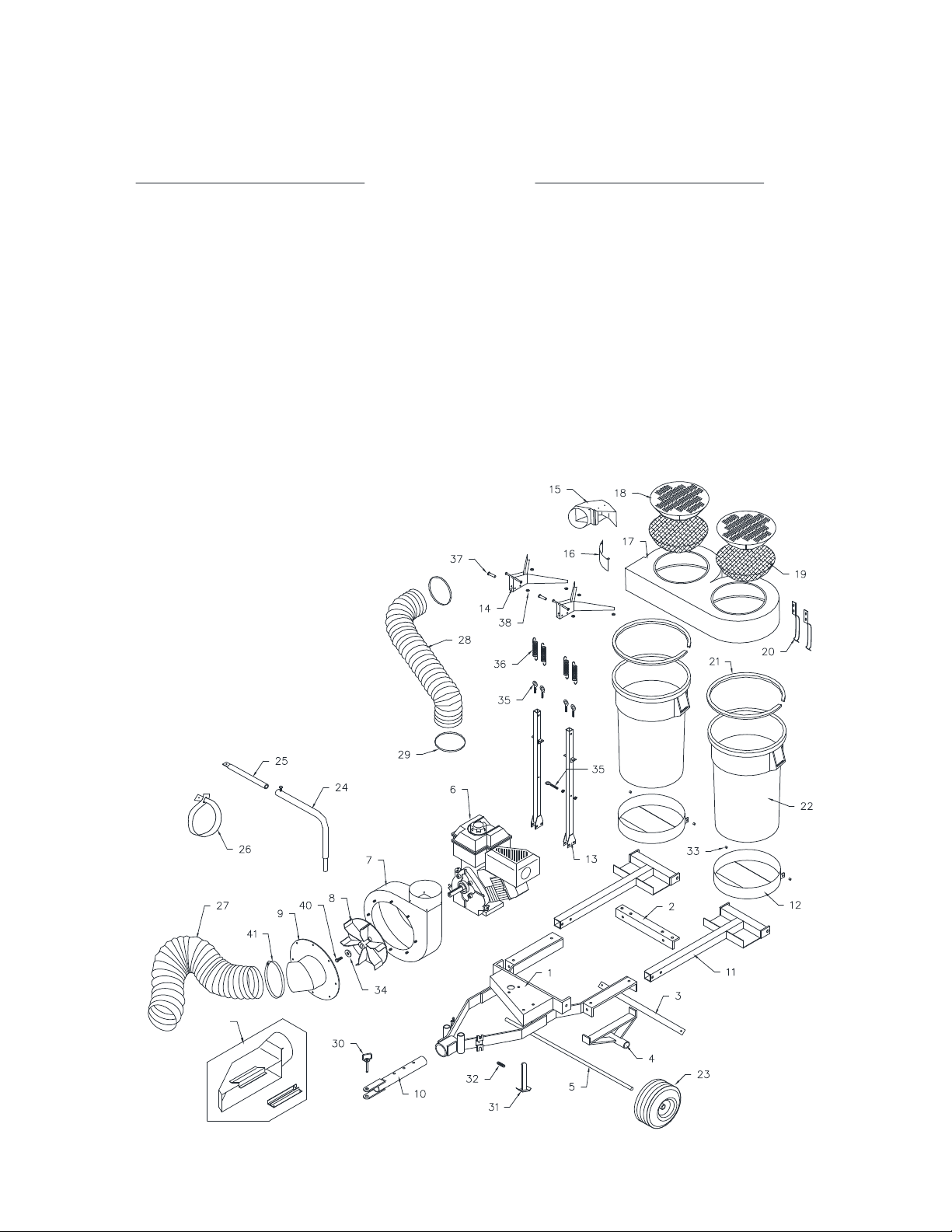
Trac-Vac Model 682
Key Qty P/N Desc. Desc.Key P/NQty
1 1 68210 Frame, 682
2 1 68211 Support Brkt.
3 1 68017 Axle Holder Brace
4 2 68014 Axle Support
5 1 68018 Axle
6 1 56020 Engine, 5.5 HP Briggs Intek
56021 Engine, 5.5 HP Briggs Intek IC
56018 Engine, 6.5 HP Briggs Intek Pro
56022 Engine, 5.5HP Honda
86028 Engine, 9HP Robin (Subaru)
7 1 56030 Turbine Housing (5.5 Briggs, Honda)
46242 Turbine Housing (6.5 Briggs)
8 1 56040 Turbine, 5HP (5.5 Briggs, Honda)
9 1 88040 Inlet, 8" Briggs, Honda)
1 47050 Inlet 8" (6.5 Briggs)
10 1 58063 Drawbar, 580
11 2 47014 Frame, 470-FD
12 2 47018 Container Holder
13 2 47020 Vertical Upright
14 2 46217 Top Support
15 1 68238 Exhaust Boot
16 1 46248 Filter Sheild
17 1 68222 Molded Top, Double
18 2 46227 Filter Support
19 2 46223 Filter
20 2 46235 Container Latch
21 2 46219 Seal, Molded Top
22 2 46210 44Gallon Container
23 2 68050 Wheel
24 1 58023 Support Arm
25 1 58022 Support Arm Ext.
26 1 58072 Hose Supp.Strap 6"
27 1 88101 Hose, 8" x 90"
28 1 65203 Hose, 6" x 42"
29 2 56102 Hose Clamp, 6"
30 1 58104 Hitch Pin
31 1 58071 Jack Stand
32 1 32108 Spring
33 4 47019 Bushing, Cont.Holder
34 1 56107 Spacer Turbine (5.5 Briggs, Honda)
35 5 48043 Eyebolt
36 4 48038 Spring
37 2 46218 Clevis Pin
38 6 56115 Nylon Spacer
39 1 ***-6 Deck Chute Ass'y (Deck Specific)
40 1 3120608 Turbine Bolt
41 2 18119 Hose Clamp, 8"
1 56122 Spacer Kit (Honda)
1 1526502 Muffler Deflector (Kohler)
2 45131 Decal, Trac-Vac White
1 45133 Decal, Warning
2 58106 Grease Zerk
39
2
6-28-16
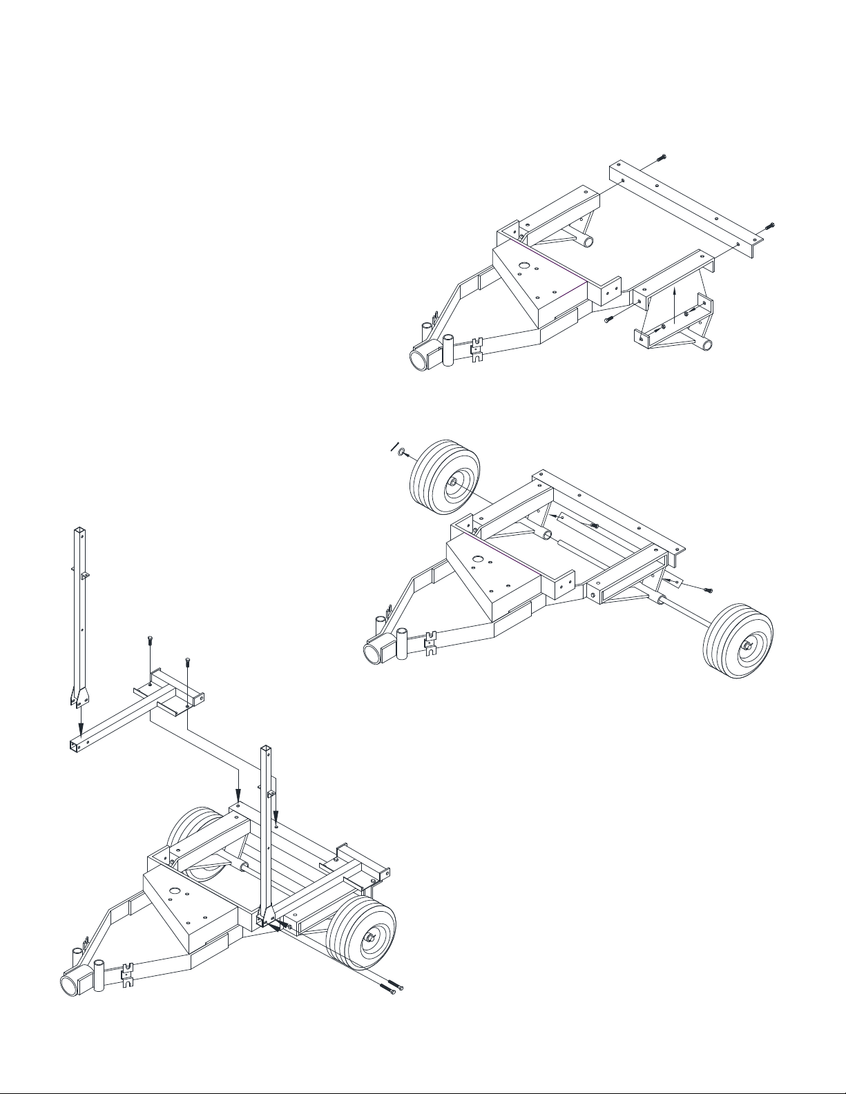
Model 682 Assembly Instructions
1.) Position axle support (4) into main frame
(1). Secure axle support, in the front
mounting hole with 3/8" x 3/4" bolts and
whizlock nuts. (Note: Axle tube should be
closest to the rear of the frame.) Position the
support bracket (2) onto the rear of the
frame and line up the two holes with the two
mounting holes for the axle support. Secure
with 3/8" x 1" bolt and whizlock nut.
2.) Insert axle (5) through axle supports (4) and
install wheels (23). Secure axle with flatwasher
and cotter pins. Attach axle holder brace (3) to
axle supports with 3/8" x 1" bolts and whizlock
nuts.
Step 1.
Step 2.
3.) Attach frame (11) to main frame (1)
using 5/16" x 3/4" bolts, flatwashers, and
whizlock nuts.
Step 3 & 4.
3
4.) Align slots on vertical uprights (13) to
holes on container holder frame (11) and ly
secure with 3/8" x 2 1/2" bolts and locknuts.
(Note: eyebolts brackets on upright should
be positioned toward container holder.)
08-26-14
 Loading...