


Model 330 & 335 TOW BEHIND
DE-THATCHER
Operating and Assembly
Manual
Midwest Equipment Mfg.
5225 Serum Plant Road
Thorntown, IN 46071
Assembly Inst ruc t i on s
3-13-12

Your Model 330 De-Thatcher comes partially assembled. Remove all parts from the
cartons to be sure you have received all parts necessary for assembly.
1. Attach Frame Mount (B) to Frame (A) with 3/8” x 3/4” HHC and Whizlock nuts
provided, three (3) on the front and two (2) on the rear. Do not tighten. Fig. 1
2. Attach wheels (J) as illustrated Fig. 2 with ½-13 x 2 3/4” HHC, ½” USS flat washer
and locknut provided.
3. Next, attach draw strap (C) to frame mount (B) with 3/8” x 1” HHC and locknuts
provided. Note: Draw strap (C) mounts to the outside of the Frame mount (B). Bolt
drawbar (D) to draw strap with 3/8” hardware as illustrated. Fig. 3
4. Bolt the Lift Handle (E) to the drawbar, (D) with the 5/16-18 x 1 ½” HHC, Spring (K),
and lock nut as illustrated. Fig. 4
5. Bolt together two (2) Lift brackets (G) with 5/16 x ¾” HHC and Whizlock nuts as
illustrated. Bolt one end of the assembled lift brackets to the top hole in the lift handle
(E). Bolt the other end of the lift brackets to the upright bracket on the frame mount (B)
Do not tighten hardware until all adjustments have been made. Fig. 5
6. Attach de-thatcher to tractor. Adjust frame mount (B) so that all four rows of tines on
the frame (A) sit level on the ground when the lift handle (E) is in the operating position.
Fig.6
7. Tines should be no deeper than ¼” below wheels. With handle in transport position,
tines should clear the ground. Tighten all hardware and test operation. Check all
hardware periodically for tightness.
1
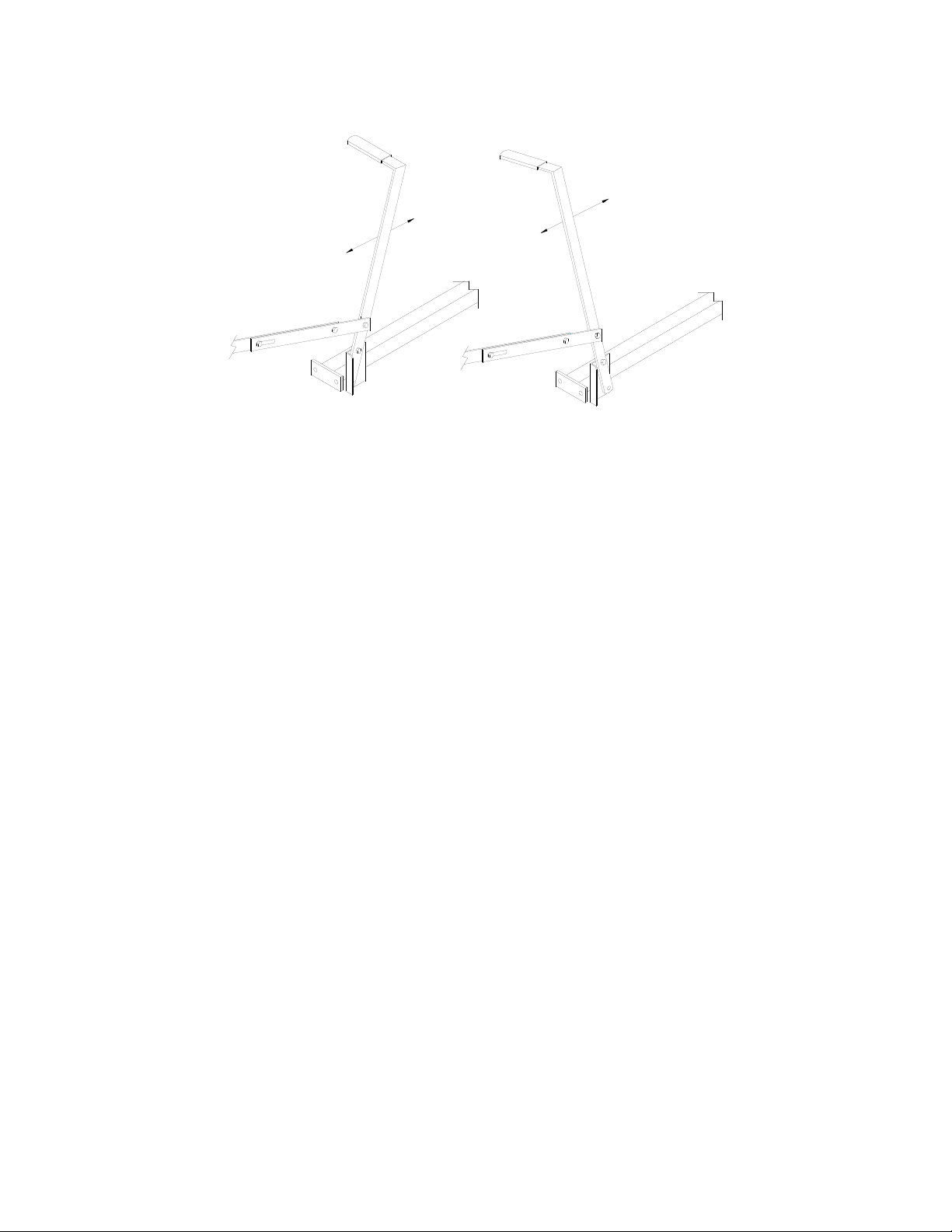
OPERATING POSITION
TRANSPORT POSITION
2

FIG. 5
FIG.2
FIG. 1
FIG.4FIG. 3
FIG. 6
3

Key
Part No.
Des
cription
A
33010
Frame, 330, 48"
B
33020 Frame Mount
C 32524
Draw Strap
D
32525 Draw Bar
E
32528
Lift Handle
F
32521
Hand Grip
G 32530 Lift Bracket
H
58104 Hitch Pin
I
32101 Tine
J
32104
Wheel
Qty.
1
1
1
1
1
1
2
1
24
2
Model 330 Tow Behind De-Thatcher
A
B
C
D
E
F
H
I
J
K
32108
Spring
1
K
33090
Hardware Bag
1
G
33510
Frame, 335, 56"
4

TRAC VAC WARRANTY POLICY
5

Midwest Equipment Mfg. will repair or replace, free of charge, any part, or parts that are
defective in material or workmanship or both for a period of one year residential use, and
90 day’s for commercial and rental use. The purchaser will pay transportation charges on
parts submitted for replacement under warranty. For warranty service, contact your local
dealer from whom the unit was purchased. There are no other express or implied
warranties. Some states do not allow limitations on how long an implied warranty lasts,
and some states do not allow the exclusion or limitation of incidental or consequential
damages, so the above limitation and exclusion may not apply to you. This warranty
gives you specific legal rights and you may also have other rights, which vary from state
to state.
MIDWEST EQUIPMENT MFG.
5225 Serum Plant Rd.
Thorntown, IN 46071
Phone: 1-800-Trac-Vac
Web Page: www.trac-vac.com E-Mail: sales@trac-vac.com
6
 Loading...