

Page 1
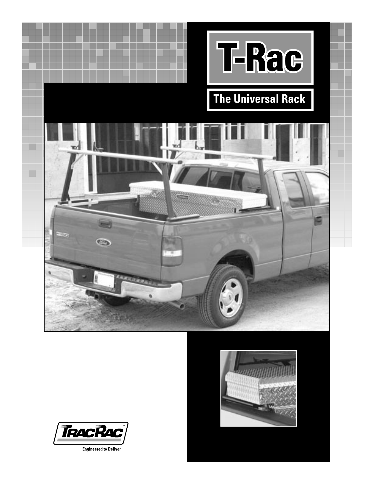
Toolbox Mount Kit
Installation Manual
SKU# 22920
Page 2
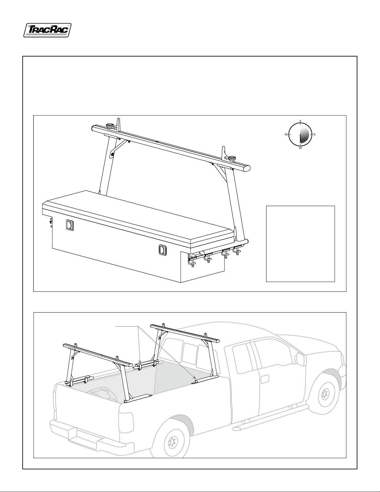
Installation Notes:
• This Kit will mount your toolbox to the Compression Mount T-Rac.
• Installation is straight forward, and should take approximately 30 minutes to complete..
1. Verify that you have received the correct parts using the assembly drawing and packing list.
Estimated assembly 30 minutes
Tools Required
1) Socket Wrench
2) 9 /16” Socket
3) 5 /16” Allen Wrench
4) Pencil
5) Measuring Tape
6) Drill & 7/16 Drill Bit
2. Start by removing the two rear clamps on the front rack (the toolbox style rack) See Figure 1.
Remove these two clamps
2 T-Rac ToolBox Mount Kit INSTRUCTION MANUAL
Figure 1. Clamp removal
TracRac Inc. 994 Jefferson Street, Fall River, MA 02721-4893 • 508-677-4130
Page 3

3. There are two styles of toolbox mount clamps: front and rear. Cut two pieces of foam tape, 1-3 /4” long and affix them to
the rear toolbox mounting clamps where shown (See figure 2).
Front Clamp Rear Clamp
U-channel
Apply foam
to this surface
Cap screw
Figure 2. Clamp designation and
tape placement
4. Thread cap screws into clamps; fit U-Channel on end of each cap screw (See Figure 2). Slide the front clamp onto each
base rail. Next re-install and tighten the base rail clamps that were removed. Slide the rear clamp on the truck siderail.
Note: do not tighten the toolbox clamps. Position toolbox on clamps, making sure toolbox lid can open. Remove toolbox,
and tighten clamps into position. Note: Clamps on both sides should be equal distance along baserail (See Figure 3).
Side View Top View
Front clamps equal distance
Position so lid can open
Position so lid
can open
Rear clamps equal distance
Front toolbox clamp
Rear toolbox clamp
TracRac Inc. 994 Jefferson Street, Fall River, MA 02721-4893 • 508-677-4130
Figure 3. ToolBox Placement
T-Rac ToolBox Mount Kit INSTRUCTION MANUAL 3
Page 4

5. Transfer hole locations from the clamps onto the toolbox.
• Measure the distance between clamp mount hole centers (Measurement “A”).
• Measure the width of the toolbox belly (Measurement “B”).
A
Figure 4. Toolbox Measurements
B
Use the chart on Figure 5 to calculate where to mark the centerlines for your holes.
A minus B = C. Then C divided by 2 = D.
Record Measurements Here:
Measurement A: ...............................
Minus
Equals C: ..............................................
Measurement B: ................................
D
Divide C by 2 to get
Measurement D: ................................
Hole centerline
D
Figure 5. “D” Dimension
4 T-Rac ToolBox Mount Kit INSTRUCTION MANUAL
TracRac Inc. 994 Jefferson Street, Fall River, MA 02721-4893 • 508-677-4130
Page 5

6. Place the toolbox back onto the mounting clamps. Mark the side of the toolbox where each clamp center is located (remember to position the box so the top can open). Take the box off, flip it upside-down and transfer the marks to the “D”
dimension centerlines. Drill 7/16” holes for each clamp location (See Figure 6).
Transfer marks to intersect
with the “D” dimension.
Drill 7/16” holes (both sides)
Avoid interference
D
Dimension
Transfer marks to intersect
with the “D” dimension.
Drill 7/16” holes (both sides)
TracRac Inc. 994 Jefferson Street, Fall River, MA 02721-4893 • 508-677-4130
Figure 6. Hole Location Marking
T-Rac ToolBox Mount Kit INSTRUCTION MANUAL 5
Page 6

7. You are now ready to at tach the toolbox to the clamps using the supplied fasteners (See Figure 7).
8. Inser t the fasteners through the washers and the holes in the toolbox, and thread into the mount clamps.
9. Torque the fasteners to 240 In-Lbs.
Head hex screw
Lock washer
Figure 7. Toolbox attachment
Note: For tool boxes over 24” wide, or that are overloaded, it’s recommended that a strip of plywood or metal be used
between the toolbox and clamps, on each side, for support.
6 T-Rac ToolBox Mount Kit INSTRUCTION MANUAL
TracRac Inc. 994 Jefferson Street, Fall River, MA 02721-4893 • 508-677-4130
T-Rac_TBMK_IM_12.12.06
 Loading...