

Page 1
SKU# 00-25850 Series
Installation Manual
Trac Rac, Inc.
994 Jefferson Street • Fall River, MA 02721
800.501.1587
www.tracrac.com
NOTES:
For good perf ormance and safety, we recom mend re-torquing all clamps and fas teners to the proper speci fications afte r the first 50 0
miles and every 5 000 miles th ereafter.
Carryin g high loads over rough roads with e xcess speed may damage the system o n your truck. Exercise go od judgement at all times.
Please call us with quest ions or concerns: 800 .501.1587 or email: info@ tracrac.com
Page 2
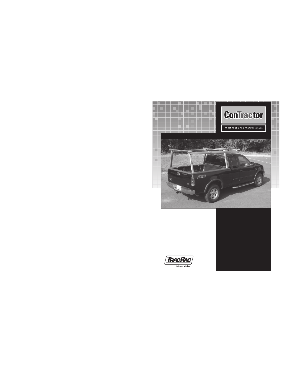
2 Contractor Rac Pro
INSTRUCTION MANUAL
TracRac Inc. 994 Jefferson Street, Fall River, MA 02721-4893 • 800-501-1587
Installation Notes :
• Contract or Rac Pro mounts onto t he side rails of your truck wi thout drilling.
• Installation is st raight forward, and s hould take approximatel y 45 minutes to comple te.
1. Verify tha t you have received the correct par ts using the assembl y drawing and packing list .
Contractor Rac Pro
2. Instal l the cleat using two bol ts (3/16” A llen
Wrench). Loosely att ach bottom of the corner
braces to all four upri ghts using hex bolt
(16mm socket) .
Table 1. Tools Required
1) Socket Wrench
2) 13mm, 15mm , 16mm
and 17mm Sockets
3) 5mm Al len Wrench
4) 3/ 16” and 5/16”
Allen Wrench
Recommended
1) Torque Wrench
Figure 2. Cleat and Corner Brace installation.
Figure 1. Contractor Rac Pro Installed on a truck bed.
Item
No.
1
2
3
4
5
Qty.
1
2
1
1
1
Table 2. Cleat and Corne r Brace Parts
Description
Cleat
Bolt 1/4-20X1.75
Corner Brace
Hex Bolt,
M10-1.5X2 5
Heavy Washer,
M10, THICK
Part No.
PI-11009
HD-80 136
01-220 08
HD-2314 3-1
HD-2319 3
1
UPRIGHT
2
3
45
Contractor Rac Pro
INSTRUCTION MANUAL
7
TracRac Inc. 994 Jefferson Street, Fall River, MA 02721-4893 • 800-501-1587
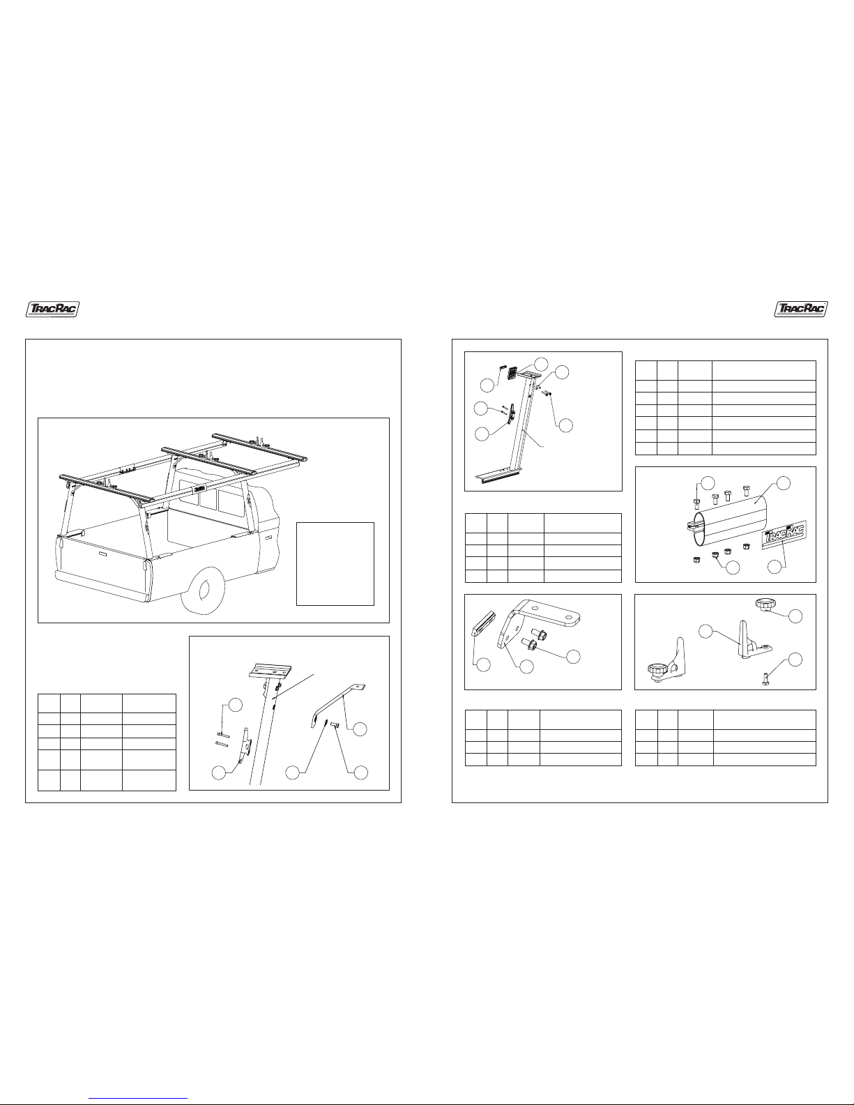
Figure 13. Upright Parts.
Item
No.
1
2
3
4
5
6
Qty.
1
2
1
1
2
2
Table 7. Upright Part Refe rence
Description
Cleat
Bolt 1/4 -20X1.75”
Nut Bar
Spacer, Cantilever
Bushing, Oval Tube
Hex Flange Bolt , M8X1.25, 5 0mm
Part No.
PI-11009
HD-80 136
FX-11139
PI-23 327
FX-9 0138
HD-23163-1
Figure 14.
Cantilever
Clamp Parts.
Item
No.
1
2
3
4
Qty.
1
1
1
4
Table 8. Cantilever Clam p Part Reference
Description
Cantilever Clamp
Label, TracRac
Lock Nut M10X1.5
Bolt, M10X1.5, 35mm Hex
Part No.
01-11144
BL-22000-D
HD-2317 9
HD-2316 5
Figure 15. Forward
Bracket Parts.
Figure 16. Tie Down Kit.
Item
No.
1
2
3
Qty.
1
1
2
Table 9. Forward Br acket Part Reference
Description
Nut Bar
Bracket, Forward
Bolt, M8X1.25, 16mm Hex Flange
Part No.
FX-11139
01-11142
HD-2316 3
Item
No.
1
2
3
Qty.
2
2
2
Table 10. Tie Down Kit Par t Reference
Description
Tie Down Zinc Diecast
Knob, Female 3/8-16 UNC
T-Bolt #3 /8-16X1-1/8, S S
Part No.
10-25111
KB-9 0004
HD-80 122
NOTES: Although the Con tractor Rac is capable of carrying a maxim um of 1250 lbs, evenly distribut ed between both racks,
the capability is limi ted to the strength of the tru ck sidewall it is mounted on. More infor mation on back cover.
1
UPRIGHT
2
3
4
5
6
4 1
3
2
1
2
3
1
2
3
Page 3

6 Contractor Rac Pro
INSTRUCTION MANUAL
TracRac Inc. 994 Jefferson Street, Fall River, MA 02721-4893 • 800-501-1587
10. Built forward crossbar assembly by following the steps of the
standard crossbar assembly except slide 4 bolts (item 1) into
bottom groove of the crossbar (2 per side). Attach the end caps.
Loosely attach the bracket assemblies to the crossbar using lock
nuts and 15mm socket.
11. Loosen two bolts (13mm socket) on the forward bracket assemblies.
Slide the nut bar into the cantilever groove on each side.
12A. Align the bracket with the end of the front cantilever.
12B. Tighten two bolts using 13mm socket (Torque 90-110 lbs).
12C. Tighten two nuts using 15mm socket (Torque 220-240 lbs) on each side.
12D. Press the end caps into the front and rear cantilevers.
Make sure that all bolts and nuts are tightened up.
Assembly is completed.
Figure 10. Forward Crossbar assembly.
Item
No.
1
2
3
Qty.
4
2
4
Table 6. Forward Cr ossbar assembly par ts
Description
T-Bolt, M10-1.5X25
Bracket, For ward
Lock Nut #10 -1.5
Part No.
HD-80 218
01-250 51
HD-2317 9
Figure 11A. Crossbar installation. DETAIL A.
Figure 11B. Crossbar installation. DETAIL B.
Figure 12. End cap installation.
BRACKET
ASSMEBLY
1
BRACKET
ASSMEBLY
2
3
FORWARD
BRACKET
ASSMEBLY
TWO BOLTS
FRONT
CANTILEVER
NUT
BAR
CANTILEVER
GROOVE
TWO
BOLTS
TWO
NUTS
END CAP
P/N PI-23326
Contractor Rac Pro
INSTRUCTION MANUAL
3
TracRac Inc. 994 Jefferson Street, Fall River, MA 02721-4893 • 800-501-1587
3. After selecting the correct hole pattern for your truck
(using Figure 3), plug up all other holes using the black
plastic ri vets. Large rive t–on the top, small ri vet–on
the bot tom (Figure 4).
Figure 3. Footprint for base of uprights.
Item
No.
1
2
Qty.
15
15
Table 3. Plastic Rivet s
Description
Rivet, Small, Ratchet, Black
Rivet, Large, Ratchet, Black
Part No.
PI-23 328
PI-23 329
4. Attach rubber block assembly and rubber shim to uprights
using socket head cap bolt, washer, rubber shim, rubber
block and brass square pocket nut, see Figure 4. Complete
all four upright as semblies. Do not at tach the L-Rail
clamps (ite ms 1,9 and 10), see Figure 5. NOTE: Mat ch
the hole patterns i n the rubber shims to the correct
upright. Flat surf ace of rubber shim must face down.
Figure 4. Front upright
assembly.
Item
No.
1
2
3
4
5
6
7
8
9
10
Qty.
4
2
2
2
1
1
1
1
2
2
Table 4. Upright Ass embly Parts
Description
Bolt Socket Head Cap, 3/8-16x3.00”
3/8 Was her, THIN
Rubber Block
Sq Pocket Nut , Brass
Rubber Shim, Fro nt LH
Rubber Shim, Fro nt RH
Rubber Shim, Rear L H
(Not Shown )
Rubber Shim, Rear RH
(Not Shown )
Clamp, L-Rail
U-Channel 3” L ong
Part No.
HD-11011
HD-80 078
RX-11031
01-2100N
FX-23 269
FX-23 270
FX-23 271
FX-23 272
01-232 22
01-22911
FRONT
DODGE
FORD F150
CHEVY
TOYOTA TUNDRA
RH
GMC
FORD F250/350
UPRIGHT BASE
(VERTICAL OVAL TUBE
NOT SHOWN)
TOYOTA TUNDRA
DODGE
FORD F150/250/350
CHEVY
GMC
RH
REAR
LH
LH
SNAP IN THEM TOGETHER
UPRIGHT BASE BETWEEN
THEM NOT SHOWN
10
2
FRONT
UPRIGHT
LH
FRONT
UPRIGHT
RH
RUBBER SHIM
FLAT FACES DOWN
SMALL
RIVET
LARGE
RIVET
5
6
9
1
2
1
3
4
Page 4

Contractor Rac Pro
INSTRUCTION MANUAL
5
4 Contractor Rac Pro
INSTRUCTION MANUAL
TracRac Inc. 994 Jefferson Street, Fall River, MA 02721-4893 • 800-501-1587 TracRac Inc. 994 Jefferson Street, Fall River, MA 02721-4893 • 800-501-1587
8A. Attach each crossbar onto a lef t and right upright by ins erting the T-bolts t hrough the saddle plate and cor ner brace
holes. At tach 6 locknuts leaving t hem loose for adjustmen ts.
8B. Center the crossb ar left to right. C rossbar should fit fl at on the saddle plats, ti ghten the T-bolt nuts usi ng 15mm socket.
Torque T-bolt nuts to 220-2 40 in-lbs.
9. Follow s teps 1 through 6 (See Figure 9 ) to install the fro nt and rear cantilevers.
Figure 8. Crossbar installation.
Figure 9. Front and Rear Cantilever installati on.
5. Inser t the rubber block into the stake pocket opening and tighten up the bolt
using 5/16 Allen Wrench. Torque to 90-110 in-lbs.
6. Slide one clamp into the base of each upright. Position as shown and secure
using socket head cap bolt and U-channel. Tighten up the bolt using 5/16 Allen
Wrench. Torque to 130-150 in- lbs.
7A. Build two standard crossbar assemblies. Assemble two tie downs–items 1, 2
and 3 (See Figure 7 and Table 5). Slide them into the top groove of the crossbar.
7B. Slide 6 T-bolts (item 5) into the bottom groove of the crossbar (3 per side).
NOTE: The flat recess of the crossbar must face down.
7C. Attach the end caps (item 6) using screws (item 7) using 5mm Allen Wrench.
Figure 5. Upright installation.
Figure 6. Clamp attachment.
Item
No.
1
2
3
4
5
6
7
Qty.
2
2
2
1
6
2
2
Table 5. Standard Cr ossbar Assembly
Description
Tiedown
Knob, Female 3 /8-16 UNC
T-Bolt 3/ 8-16X1-1/8, SS
Crossbar, Triple T-Slot
T-Bolt, M10X1. 5, 25mm
Crossbar Endcap
Bolt M6X1
Part No.
10-25111
KB-9 0004
HD-80 122
01-10540
HD-80 218
PI-23 325
HD-232 76
Figure 7. Standard crossbar assembly.
CLAMP
BASE
TOP
FRONT
BOTTOM RECESS
4
5
6
7
4
1
2
3
EQUAL DISTANCE
SADDLE
SADDLE
CORNER
BRACES
LOCK NUT, M10X1.5
P/N HD-23179
15MM SOCKET
EQUAL DISTANCE
SLIDE REAR CANTILEVER
(SHORT FOR SHORT BED)
ON T-SHAPE NUT BAR
SLIGHTLY UNSCREW
TWO BOLTS
(13mm SOCKET)
SLIDE CLAMP ASSEMBLY
ON REAR CANTILEVER
SLIGHTLY UNSCREW TWO
BOLTS AND SLIDE
FRONT CANTILEVER ON
T-SHAPE NUT BAR
ALIGN REAR CANTILEVER WITH REAR UPRIGHT
AND TIGHTEN UP TWO BOLTS
FRONT
CANTILEVER
SLIDE FRONT CANTILEVER INTO
CLAMP CENTER CLAMP AND
TIGHTEN UP FOUR BOLTS
(15mm AND 17mm SOCKETS)
THEN TIGHTEN UP TWO BOLTS
OF FRONT UPRIGHT
REAR
CANTILEVER
1
2
6
4
5
3
 Loading...