

Page 1
IN-25854 Rev. H
Page 2
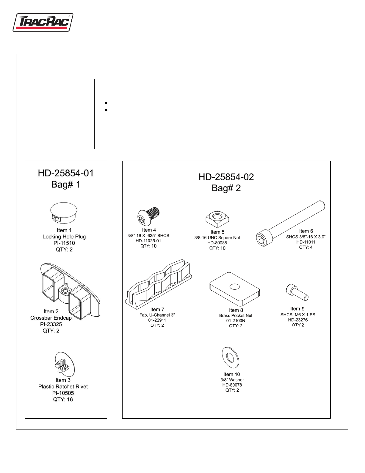
Table 1. Tools Required
1) Socket Wrench
2) 17 mm Socket
3) 5mm Allen Wrench
4) 5/16" Allen Wrench
5) 7/32" Allen Wrench
6) Tape Measure
CabRac Installation Manual
Installation Notes:
CabRac mounts onto the side rails of your truck without any drilling
Installation should take approximately 50 minutes to complete
Recommended
1) Torque Wrench
1. Verify that you have received the correct parts using the following parts list, along with
the assembly and packing check list.
Note: For ease of installation, assembly should be done prior to installation onto truck.
2 CabRac INSTRUCTION MANUAL
TracRac Inc. 994 Jefferson Street, Fall River, MA 02721-4839 * 800-501-1587
Page 3
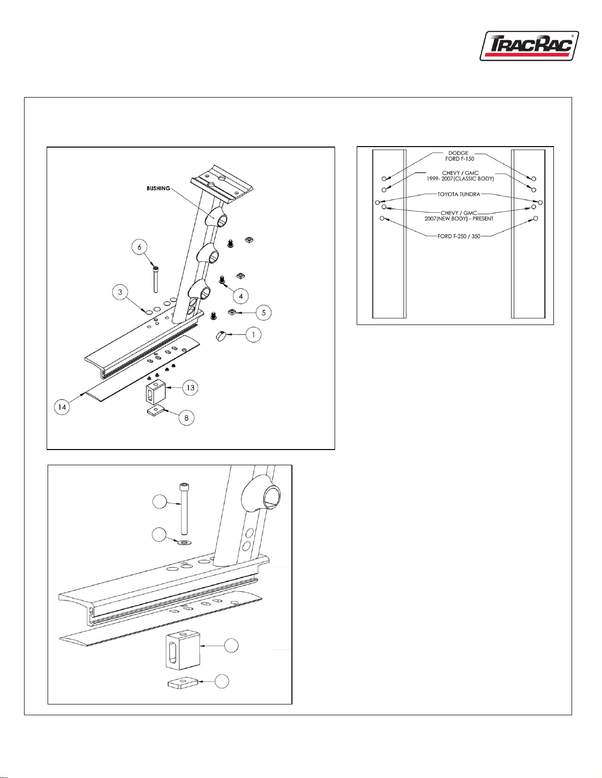
Figure 1.
Figure 3.
10
LEFT AND RIGHT UPRIGHT ASSEMBLY
Figure 2.
1. Using Figure 2 select the correct mounting hole
for your truck. Once hole is selected, plug the
remaining holes using the plastic ratcheting
rivets (item 3).
2. Assemble 3/8"-16 x 3.0" socket head cap screw
(item 6) and 3/8" washer (item 10). Insert the
assembly through the selected mounting hole
for your truck. On the underside of the upright
base insert the rubber shim*, then the rubber
expansion block, finally thread on the brass
pocket nut (item 8). Reference Figure 3. Note:
The brass pocket nut shall be tightened so that
6
the rubber block and nut do not rotate freely.
They will be fully tightened later on in the
assembly.
3. Insert 3/8"-16 x .625" button head cap screw
(item 4) into screw hole located on the underside
of the CabRac bushing. At the same time thread
on the stainless steel square nut (item 5) only
so that the button head cap screw does not fall
out. This will be tightened down later on in the
installation. Reference Figure 1.
TracRac Inc. 994 Jefferson Street, Fall River, MA 02721-4839 * 800-501-1587
9
5. Repeat steps 1-4 for the remaining uprights.
4. Repeat step 3 for the remaining bushings.
8
* There is a left and right rubber shim. The hole
pattern will match its corresponding upright base.
CabRac INSTRUCTION MANUAL 3
Page 4

CROSSBAR ASSEMBLY
Figure 4.
1. Slide four square nuts (item 5) into the bottom T-Slot on the crossbar. Reference Figure 4.
2. Insert a crossbar end cap (item 2) into each end so that the flat edges of the end caps line up with the edge of
the crossbar. Reference Figure 4.
3. Secure end caps with M6 x 1 (item 9) socket head cap screw using the 5mm Allen Wrench through the
bottom of the crossbar. Reference Figure 4.
4 CabRac INSTRUCTION MANUAL
TracRac Inc. 994 Jefferson Street, Fall River, MA 02721-4839 * 800-501-1587
Page 5

T-SLOT CROSSTUBE INSTALLATION
Figure 5.
Figure 6.
Note: Length on tubes increase from top to bottom. Top tube being
the shortest.
1. Insert the shortest tube into the top CabRac bushing onto the
assembled upright, making sure that the square nut is located on
the inside of the T-Slot. Reference Figures 5 and 6.
TracRac Inc. 994 Jefferson Street, Fall River, MA 02721-4839 * 800-501-1587
2. Repeat for the remaining cross tubes.
3. After all three cross tubes are lightly secured, insert the other
assembled upright onto the opposite end of the tubes.
CabRac INSTRUCTION MANUAL 5
Page 6

Figure 7.
CROSSBAR INSTALLATION
1. Measure the inside bed width just behind the cab of your truck and set dimension A to that measurement (Figure 7).
2. Tighten the socket head cap screws located on the bottom of all six bushings using the 7/32" Allen Wrench. Torque
to 138 in/lbs.
3. Install cross bar onto saddle plates of the assembled uprights making sure that the four button head cap screws are
through the saddle plates.
4. Before tightening down the cross bar ensure that it is centered be equaling measurements B (Figure 7).
5. Tighten down the cross bar using a 7/32" Allen Wrench. Torque to 324 in/lbs.
CAUTION: Structural rigidity depends on installation of the cross tubes. Failure to install will result in undesired
performance and void the factory warrenty.
6 CabRac INSTRUCTION MANUAL
TracRac Inc. 994 Jefferson Street, Fall River, MA 02721-4839 * 800-501-1587
Page 7

MOUNTING CABRAC TO THE TRUCK
Figure 8.
CAUTION: TracRac strongly recommends the following
step be completed with the help of another person.
7
Figure 9.
1. Lift the assembled CabRac and mount it to the truck bed
6
side walls by inserting the rubber expansion blocks into
the stake pockets. Secure rubber block by tightening the
3/8"-16 screw using the 5/16" Allen wrench. Reference
Figure 6. Torque to 160 in/lbs.
2. Next you will need to build two of the L-Rail clamps by taking a clamp
assembly and partially threading in the 3/8"-16 x 3.0" socket head
cap screw (Item 6). Once completed place the 3" U-Channel (Item 7)
Figure
10.
on top of the 3/8" screw as shown in Figure 9.
3. Take the assembled clamp and insert it onto the matching dovetail
located on the CabRac base one inch from the end, as shown, tighten
using a5/16" Allen Wrench. Reference Figure10. Torque to 270 in/lbs.
4. Repeat for opposite side.
5. Go through all bolted connections and ensure that they all are fully
secured and tightened to the recommended torque.
Notes:
For good performance and safety, we recommend re-torquing all clamps and fasteners to the proper specifications after
the first 500 miles and every 5000 miles thereafter.
Carrying high loads over rough roads with excess speed may damage the system on your truck. Exercise good judgment
at all times.
Please call us with questions or concerns: 800.501.1587 or email: info@tracrac.com
TracRac Inc. 994 Jefferson Street, Fall River, MA 02721-4839 * 800-501-1587
CabRac INSTRUCTION MANUAL 7
Page 8

 Loading...