

Tracplus RockAIR Owner's Manual
RockAIR
Owner’s Manual v2.0
TracPlus Global Ltd
Level 4, 1 Bond Street,
PO Box 1466
Dunedin 9054
New Zealand
0800 872 275 (New Zealand)
1800 330 740 (Australia)
sales@tracplus.com
support@tracplus.com

Table of Contents
Page
Overview of the RockAIR 2
Installation of the RockAIR 7
Activating the RockAIR 12
International Roaming 12
Basic Operations 13
Advanced Operations 16
LED light indicators 17
Using the RockAIR with an iOS device 18
Troubleshooting 21
Overdue and Distress Monitoring options 22
Viewing your tracking 23
About the battery 24
Compliance 26
Overview
Thank you for your purchase of a RockAIR. We are confident that you will find
the RockAIR to be an invaluable addition to your operations to improve safety,
communication and operational eectiveness.
With correct use, your RockAIR should provide years of reliable service. This manual
sets out important information crucial to the correct installation and operation of your
RockAIR so that you get the very best results from your investment. Failure to observe
and adhere to the instructions contained in this document will compromise the ability of
the RockAIR to perform as designed.
TracPlus cannot be held responsible for any failure of the RockAIR or
supporting services arising in whole or in part from any failure to adhere to
the instructions and guidelines contained herein.
Description
The RockAIR is a portable, carry-on carry-o global communications device that allows
you to transmit tracking, events, forms and send/receive messages from anywhere in the
world using the Iridium satellite network and terrestrial cellular networks.
The RockAIR consists of a GPS receiver, Iridium SBD satellite transceiver, GPRS cellular
modem, internal satellite/cellular/GPS antennas, Bluetooth™ module, micro-controller and
backup Li-Ion Polymer battery.

Specications
1. Power/Suspend button
2. Power/Suspend LED indicator
3. Monitor button
4. Monitor LED indicator
5. External Power LED indicator
6. Bluetooth LED indicator
7. Mark LED indicator
8. Mark button
9. Distress/Distress Cancel LED indicator
10. Distress/Distress Cancel button
1
2 3 4 5 6 7 8 9
10
11 12 13 14 15 16
17 18
Dimensions
11. Iridium external SMA connector (optional)
12. GPS external SMA connector (optional)
13. Cellular external SMA connector (optional)
14. Sensor cable connector
15. Power cable connector
16. MicroUSB port
17. SD card slot (under sleeve)
18. GPRS SIM card slot (under sleeve)
100mm
(3.9”)
25mm
(1.0”)
100mm
(3.9”)
119mm
(4.7”)

Dimensions 100mm x 119mm x 25mm (3.9” x 4.7” x 1.0”)
Weight 210gm (8 oz)
Connectors USB
4-way Molex Micro-Fit (power)
6-way Molex Micro-Fit (input sensors)
Optional SMA for external antennas
Inputs Four membrane push buttons
USB serial
Bluetooth
Five configurable digital inputs
Sensors GPS
Accelerometer
Thermometer
Power loss
Impact
Screen Type None. Pair with iOS device for features requiring screen
LED Indicators 6 NVG compatible LEDs with additional ND filters
Internal Antennas GPS, Iridium, Cellular
Casing/Housing ABS/PC (Bayblend FR3010 BLK)
Elastosil LR 3003/70 A&B
Input Voltage USB (5v DC); or
Aircraft Power (9-30v DC)
Power Consumption 500mA max, plus very low current sleep mode
(<30mA)
Power Sources External DC supply with internal Li-Ion polymer
battery backup
Satellite Network Iridium via 9603 Short Burst Data (SBD) transceiver
Cellular Network GPRS (Cellular IP)
Operating Environment < 75% Relative Humidity
Operating Temperature -40°C - +85°C
Other Certifications FCC & CE
DO160 Testing DO160G
Section 15 Magnetic Eect
Section 21.4 Conducted Emission of Radio
Frequency Energy
Section 21.5 Radiated Emission of Radio Frequency
Energy DO160G
Section 4 Temperature and Altitude
Section 7.2.1 Operational Shock
Section 7.3.1 Impulse Shock
Section 7.3.3 Sustained Shock
Section 8.8.1 Vibration
Section 17 Voltage Spike
Section 26 Flammability
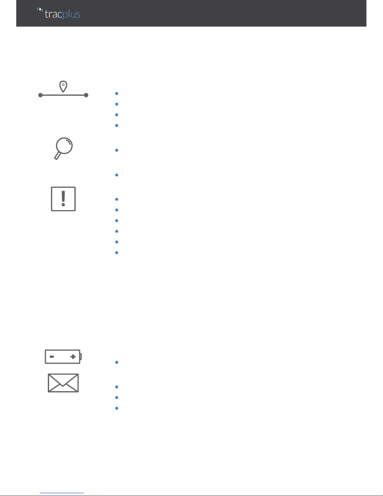
Capabilities
Tracking
• Transmit regular position reports via Iridium satellite network
• Transmit regular position reports via terrestrial cellular networks
• Automatically switch between satellite and cellular networks based on coverage
• Manually suspend tracking and automatically resume
Automated Monitoring
• Automatic monitoring with Of Concern and Overdue alerts via SMS
Marking
• Manually mark up to four dierent types of points of interest
Alerting
• Manually activate distress mode to transmit distress messages at a faster rate
• Distress notification via SMS and voice
• Manually cancel distress mode to resume normal operation
• Automatically detect and transmit impact alerts
• Automatically detect and transmit start up and shutdown messages
• Automatically detect and transmit events from external switch-type sensors
Engine start
Engine stop
Take o
Landing
Rotor start
Rotor stop
AoA limit exceedence
Any other user-definable event
Backup Battery
• Automatically transmit queued reports and messages after shutdown
Global Messaging (connected device required)
• Send/Receive text messages to/from mapping software
• Send/Receive text messages to/from cell phones
• Send/Receive text messages to/from email addresses

Forms (connected device required)
• Complete and send custom forms to mapping software
Logging
• Position and diagnostic information recorded each second to removable
MicroSD card (included)

Installation of RockAIR
Aviation use
TracPlus does not hold any STCs or TSOs for the RockAIR. The RockAIR should be
installed in accordance with the requirements of the operator and the intended use.
Installation of the RockAIR is at the discretion of a duly licensed Aircraft
Maintenance Engineer or Aircraft Maintenance Technician (AME/AMT). The following
recommendations are appropriate for New Zealand or the United States, and may apply
in other countries.
AC43-14 Appendix 9
Under New Zealand Civil Aviation Authority (CAA) Advisory Circular AC43-14 Appendix
9, eligible aircraft can have the RockAIR installed as non-aeronautical equipment.
FAA 337
The power cable for the unit may be hardwired into the aircraft power system, and
the sensor cable may be connected to independent non-critical sensors. This is a
modification performed in the field by any approved AME/AMT by submitting an FAA
337 form or equivalent. Whether the installation qualifies as a major modification will be
at the discretion of the FAA Flight Standards District Oce.
To support the installation process, TracPlus provides RockAIR owners with DO160G test
documentation. This is available on request from TracPlus and is included on USB with
the RockAIR Professional kit.
For further information, please email support@tracplus.com or call as follows:
North America (678) 782 8090
New Zealand 0800 872 275
Australia 1800 330 740
Rest of World +64 3 477 8656
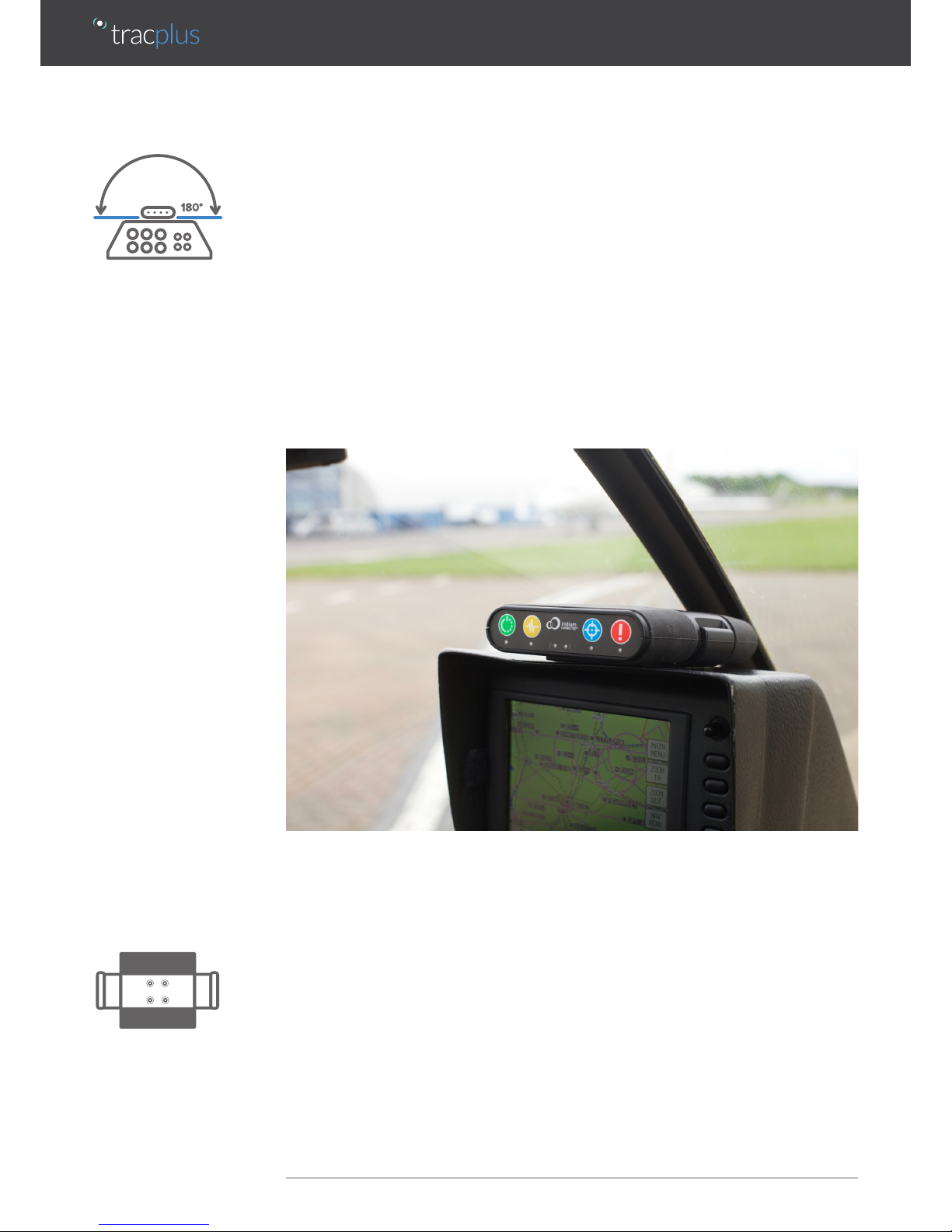
Finding the best place
The RockAIR needs to have an uninterrupted view of the sky to operate correctly. As
such, the correct placement of the RockAIR during installation is crucial. The RockAIR
should be installed so that it is level and upright; clear of obstructions and has the
greatest possible hemispherical view of the sky.
Metal, carbon-fiber or concrete objects between the RockAIR and the sky will prevent
the RockAIR from correctly operating. The RockAIR cannot reliably gain a GPS fix or
transmit and receive data when placed inside a vehicle trunk, luggage compartment,
building, or under water.
The typical mounting position for the RockAIR is on the glare-shield of your aircraft or
dashboard of your vehicle, in such a way as to maximize the view through the canopy
or windscreen¹.
If you are unable to position the RockAIR anywhere with such a view, you should
consider installing an external antenna or antennae. This is typically a dual mode
GPS/Iridium antenna and a separate cellular antenna. This requires notification at time of
purchase, or a return to your distributor for an approved modification.
Installing the mounting clip
The recommended means of installing the RockAIR is to permanently fit the provided
mounting clip to the glare-shield or dashboard, using installation-appropriate fasteners
(not included) so that the clip will not detach during an impact event.
¹ The RockAIR will not operate correctly on the glare-shield of an aircraft fitted with electrically heated windows as the fine wire mesh prevents the
transmission of radio signals.
 Loading...