

TracPhone v7ip Installation Manual

®
TracPhone
26" (66 cm) Configuration
V7IP
Installation Guide
TracPhone V7-IP and V7 (3-axis Version)
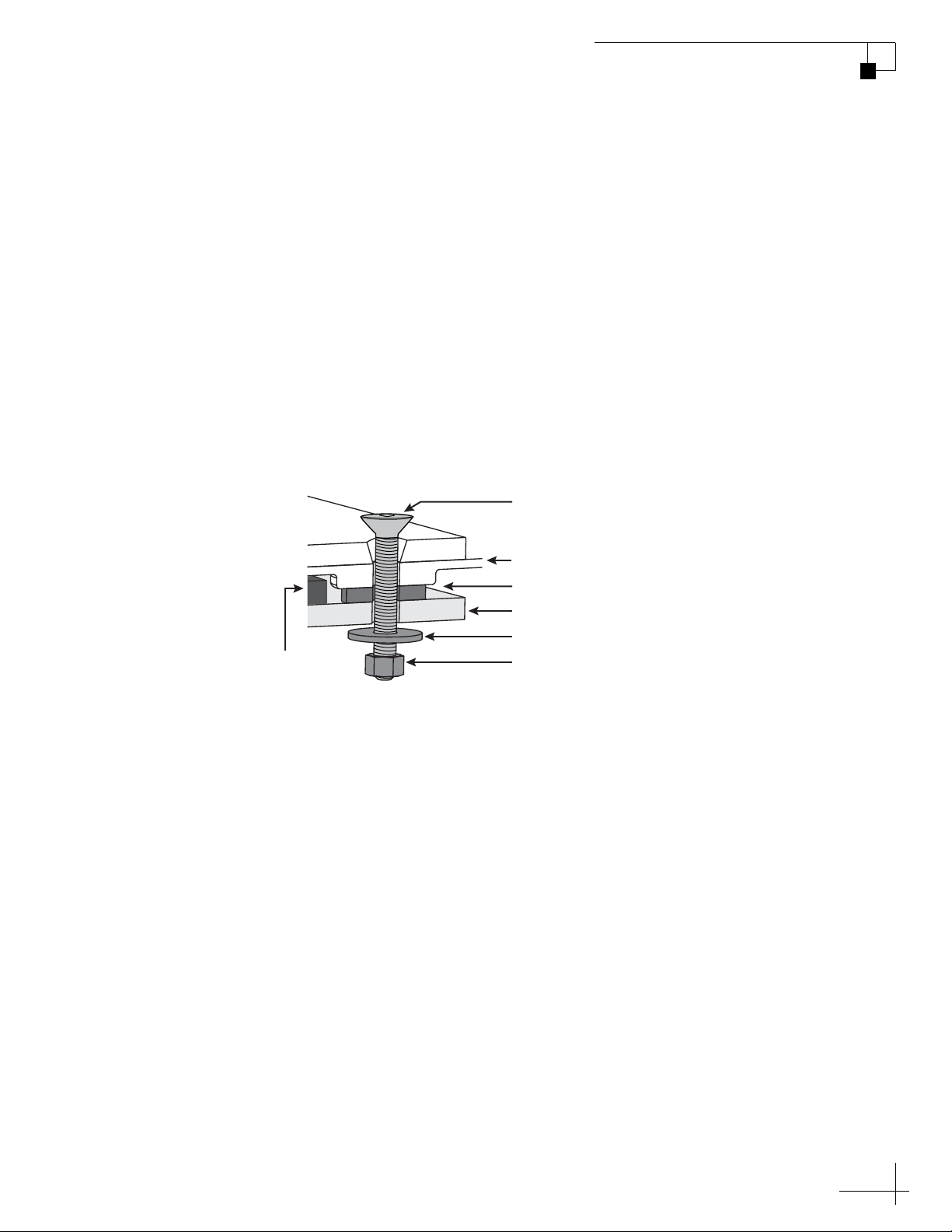
1/2"-13 Bolt (x4)
Rubber Foot (x4)
Mounting Surface
1/2" Flat Washer (x4)
1/2"-13 Lock Nut (x4)
Antenna Baseplate
Foam Seal
Apply anti-seize to threads,
Torque to 25-30 ft-lbs (34-41 N-m)
Addendum
PLEASE READ!
Important Addendum to the Installation Guide
The Installation Guide recommends an inappropriate torque setting
for tightening the antenna mounting bolts. The correct torque setting is
25-30 ft-lbs (34-41 N-m). Therefore, step e of the “Mount the Antenna”
section should read as follows:
e. Tighten all four bolts until the four rubber feet on the
baseplate are bottomed against the mounting surface
and the foam seal is fully compressed. KVH
recommends that you tighten the nuts to between 25
and 30 ft-lbs (34 and 41 N-m) of torque.
Mounting the Antenna (Side View)
54-1038 Rev. A
1
Antenna Power/Data Cable Shroud
Addendum
PLEASE READ!
Important Addendum to the Installation Guide
A cable shroud is now provided in the kitpack to protect the wires of
the power/data cable. Before you connect the power/data cable to the
belowdecks equipment, follow these steps to attach the shroud.
a. Wire the power/data cable to the terminal strip
connector as directed in the Installation Guide.
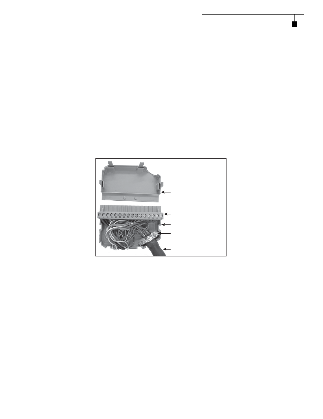
b. Place the terminal strip connector into the base of the
cable shroud, as shown in Figure 1.
Figure 1 Power/Data Cable Shroud
Cover
Terminal Strip Connector
Base
Clamp
Power/Data Cable
c. Secure the end of the power/data cable to the base of
the shroud using the supplied clamp. This clamp will
help relieve stress on the cable. Secure the clamp in
place with the two screws.
d. Carefully fit all of the cable’s wires within the base of
the shroud.
e. Snap the shroud’s cover onto the base. Be sure not to
pinch any wires between the cover and the base.
f. Plug the terminal strip connector into the rear panel of
the belowdecks equipment, as directed in the
Installation Guide.
54-0896 Rev. A
1
TracPhone V7-IP Installation Guide
mini-VSAT Broadbandsm System with CommBox-ACU
This guide explains how to install the TracPhone V7-IP mini-VSAT Broadband satellite
communications system. Operation instructions are provided in the Quick Start Guide.
Installation Steps
1. Inspect Parts and Get Tools ................. 3
2. Plan the Antenna Installation .............. 4
3. Plan the Belowdecks Installation ........ 6
4. Prepare the Belowdecks Units............. 7
5. Prepare the Antenna Site.................... 10
6. Remove the Shipping Restraints ....... 11
7. Prepare the RF Cables......................... 12
8. Wire the Antenna ................................ 13
9. Mount the Antenna ............................. 16
10. Wire the Belowdecks Equipment...... 18
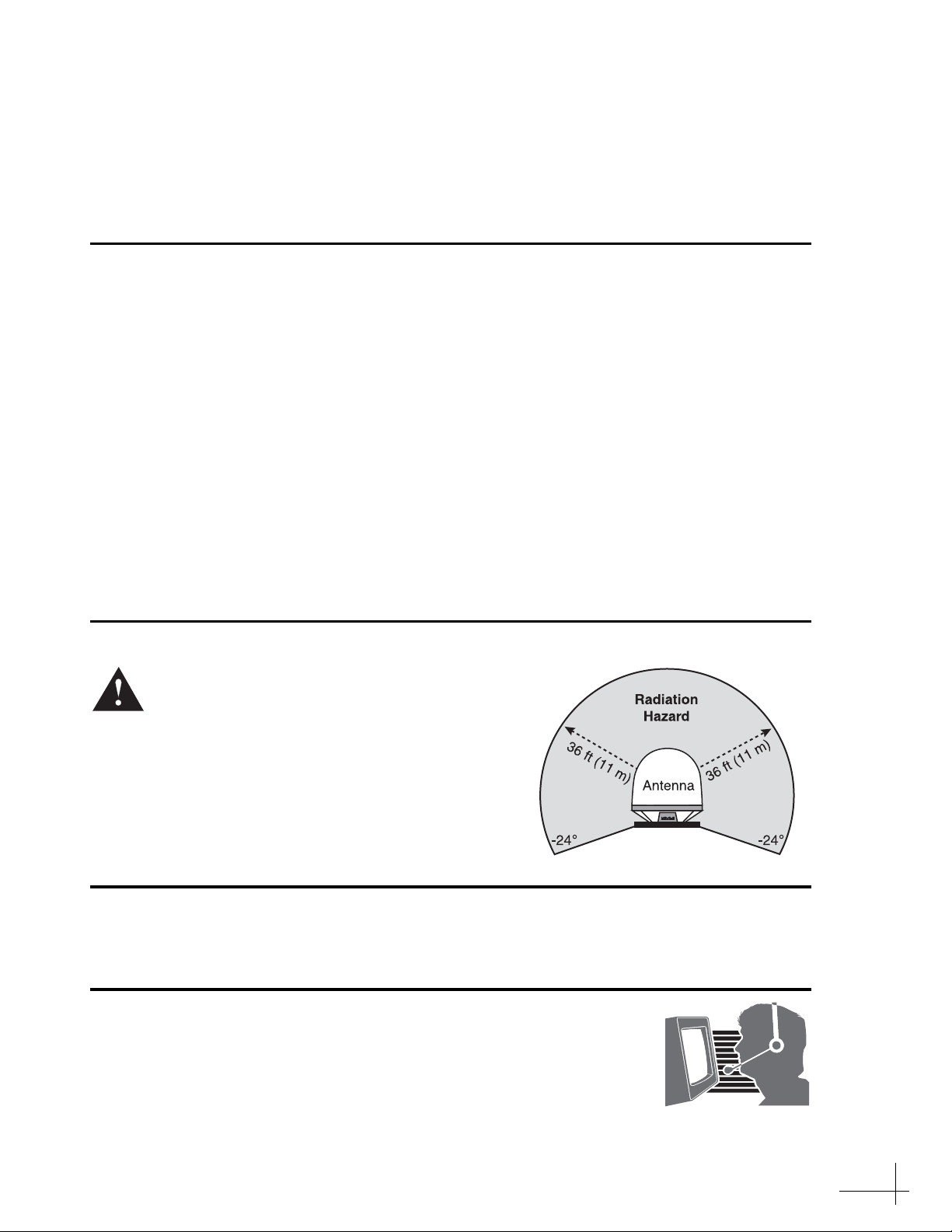
CAUTION - RF Radiation Hazard
The antenna transmits radio frequency (RF)
energy that is potentially harmful.
Whenever the system is powered on, make
sure everyone stays more than 36 feet
(11 m) away from the antenna. As shown in
the illustration, no hazard exists directly
below the antenna.
11. Connect Power......................................20
12. Turn On the System .............................22
13. Update the System Software...............23
14. Customize the Web Interface..............24
15. Set Up No-Transmit Zones .................25
16. Test the System .....................................27
17. Connect Vessel Computers.................28
18. Connect Vessel Phones & Options.....30
19. Educate the Customer..........................31
Who Should Install the System?
To ensure a safe and effective installation, only a KVH-certified technician should install the
TracPhone system. To find a technician near you, visit www.kvh.com/wheretogetservice.
Technical Support
North/South America, Australia:
Phone: 1 866 701-7103 (U.S. only)
Phone: +1 401 851-3806
E-mail: mvbsupport@kvh.com
KVH, TracPhone, CommBox, and the unique light-colored dome with dark contrasting baseplate are trademarks of KVH Industries, Inc.
mini-VSAT Broadband is a service mark of KVH Industries, Inc. All other trademarks are property of their respective companies.
The information in this document is subject to change without notice. No company shall be liable for errors contained herein.
© 2012-2013 KVH Industries, Inc., All rights reserved. 54-0782 Rev. B
Europe, Middle East, Asia, Africa:
Phone: +45 45 160 180
E-mail: mvbsupport@kvh.com
1

CE Declaration of Conformity
The undersigned of this letter declares that the following equipment complies with the
specifications of EC directive 1999/5/EC Radio & Telecommunications Terminal Equipment.
Equipment Included in this Declaration
TracPhone V7-IP system, consisting of:
• 02-1925-XX
• 02-1875-02 TracPhone CommBox-ACU
• 19-0773 TracPhone Modem
1
The part number is followed by two alphanumeric characters which designate non-performance-
affecting customer-specific branding.
Equipment Applicability
The TracPhone V7-IP system provides broadband Internet connectivity between a ship and any
destination in the world. The equipment is not intended for SOLAS applications.
Declaration and Certification
The TracPhone V7-IP system complies with the following harmonized standards under the
R&TTE Directive 1999/5/EC:
1
or 02-1926 TracPhone V7-IP Antenna
Essential Requirement Applied Standard(s)
Article 3.1(a) Health & Safety EN60950-1:2006 + A1:2009
Article 3.1(b) EMC EN 301 843-1 v1.2.1:2004-06,
EN 301 843-6 V1.1.1:2006-01,
EN61000-3-2:2006,
EN61000-3-3:1995, A1:2001 & A2:2005
EN60945:2002
Article 3.2 Spectrum Efficiency EN302 340 V1.1.1:2006-04
Manufacturer
KVH Industries, Inc.
50 Enterprise Center
Middletown, RI 02842-5279 USA
Rick Jones, Director of Corporate Quality Date
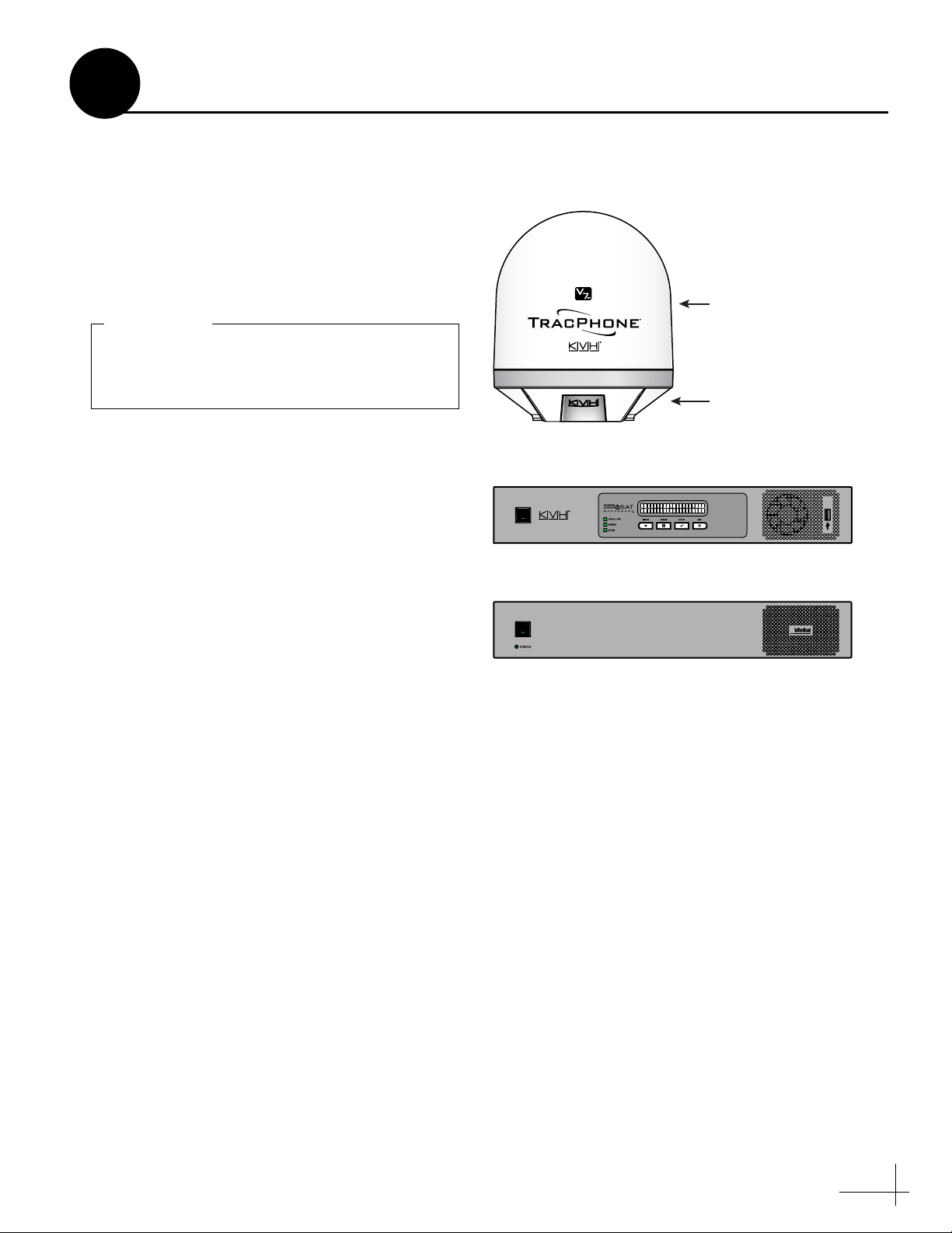
Figure 1: TracPhone V7-IP System Components
Always lift the antenna by the baseplate and
never by the radome or any portion of the
internal antenna assembly (see Figure 1).
IMPORTANT!
• Wire stripper/terminal crimper
• File
•Two 75RF coax cables, “F” connectors, and
associated termination tools (see page 12)
• NMEA 0183 talker and interface cable (see
page 18)
• Isolation transformer, if required (see page 20)
• Laptop PC with the latest TracPhone V7-IP
CommBox-ACU/antenna software (.kvh) and
modem configuration files (.sscf/.sed)
downloaded from the KVH Partner Portal
(www.kvh.com/partners)
1
Before you begin, follow these steps to make sure
you have everything you need to complete the
installation.
a. Unpack the box and ensure it contains
everything shown in Figure 1 and on the
Kitpack Content Lists. Save the packaging for
future use.
b. Carefully examine all of the supplied parts to
ensure nothing was damaged in shipment.
c. Gather all of the following tools and
materials that you will need:
• Flat-head and Phillips-head screwdrivers
Inspect Parts and Get Tools
Antenna
(KVH part #02-1925-SL)
Radome
Baseplate
CommBox-ACU
(KVH part #02-1875-02)
• Electric drill and 5/8" (16 mm) bit
• 3.75" (95 mm) hole saw
•5/16" hex driver
•7/8" socket
• 7/16" open-end torque wrench set to
20 in.-lbs
• Light hammer and center punch
•Adhesive tape
• Silicone sealant, self-vulcanizing tape, or
equivalent
• Heat gun (for heat shrink)
• Eye protection
•Shop towels
•Voltmeter
• Utility knife
•Flush cutters
Modem
(KVH part #19-0773)
3

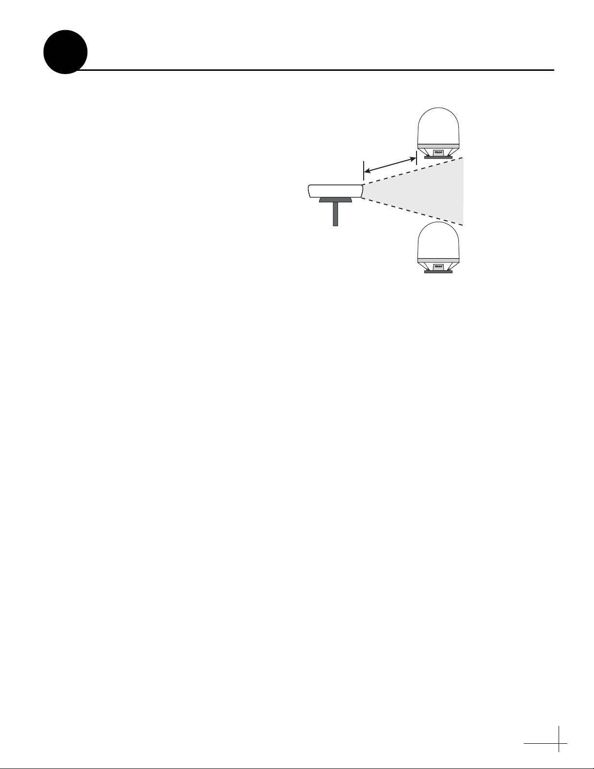
Figure 2: Blockage from Obstruction
FWD
31.17"
(791.7 mm)
26.23"
(666.3 mm)
8.49"
(215.6 mm)
4.24"
(107.7 mm)
8.49"
(215.6 mm)
4.24"
(107.7 mm)
4 x Ø.56"
(Ø14.2 mm)
Forward
Mark
Side View
Bottom View
Ø12.00"
(Ø304.8 mm)
Figure 3: Antenna Dimensions
RF emissions from radars and high-power
radio transmitters may damage the antenna
or impair its performance if it’s improperly
positioned within the beam path.
IMPORTANT!
2
Plan the Antenna Installation
Before you begin, consider the following antenna
installation guidelines:
• Minimize blockage. The antenna requires a
clear view of the sky to transmit and receive
satellite signals (see Figure 2). The fewer
obstructions, the better the system will
perform.
• Make sure the mounting surface is wide
enough to accommodate the antenna’s base
(see Figure 3). Also make sure it is flat, level
(within ±2º), strong enough to support the
antenna’s weight (57.6 lbs, 26.13 kg), and
rigid enough to withstand heavy vibration.
• Select a location that is as close as possible to
the intersection of the vessel’s centerline and
midships.
• Select a location that is well above any areas
accessible to passengers and crew to reduce
the risk of RF radiation exposure.
• Avoid placing the antenna near any magnetic
compasses or other onboard antennas to
prevent potential interference.
Blocked!
-24° to 119°
Look Angle
Antenna
Vessel Platform
Mast
Radar/High-Power Radio Transmitters
Although many variables determine the exact
distance required between the antenna and
radar/high-power radio transmitters, including
transmitter beam properties and the reflective
properties of nearby surfaces, consider the
following general guidelines when selecting a
safe antenna location:
• Mount the antenna as far away as possible
from the radar and high-power radio
transmitters.
4
Antenna
Antenna
+15°
-15°
Potential RF
Interference
10 ft (3 m)
Minimum
Radar
Figure 4: Avoiding RF Interference
2
• Do not mount the antenna at the same level
as the radar. Most radar transmitters emit RF
energy within an elevation range of -15° to
+15° (see Figure 4). Therefore, mount the
antenna outside this elevation range and at
least 10 ft (3 m) away from the transmitter.
Continued Plan the Antenna Installation
5
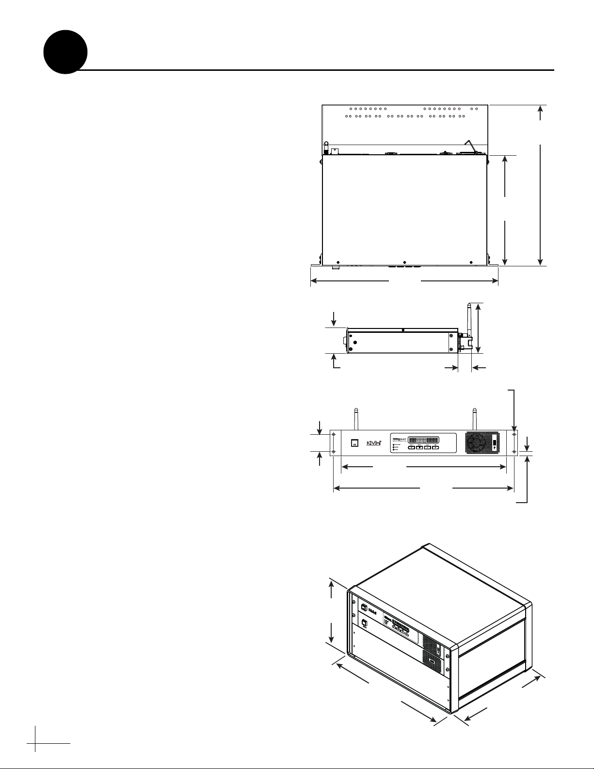
Figure 5: CommBox-ACU or Modem Dimensions (Identical)
Figure 6: Case Dimensions
3
Plan the Belowdecks Installation
Before you begin, consider the following
installation guidelines for the belowdecks units.
• Select a mounting location in a dry, wellventilated area belowdecks away from any
heat sources or salt spray.
• Be sure the front panels will be easily
accessible to the user.
• Leave enough room at the rear panels to
accommodate the connecting cables.
• There are three options for mounting the
belowdecks equipment:
Option 1 - In the optional case
Option 2 - In an onboard equipment rack
Option 3 - To a horizontal surface
NOTE: The CommBox-ACU and modem are sized to
fit a standard 19" (482.6 mm) rack, occupying 3U of
space.
• To use the supplied power/data cable, the
CommBox-ACU must be located within
100 ft (30 m) of the antenna. However, you
can order a 150 ft (45 m) cable if a longer cable
run is necessary (KVH part no. 32-1031-0150).
1.75"
(4.45 cm)
Strain-Relief Bracket
(Modem Only)
Top View
(48.26 cm)
Side View
2.63"
(6.68 cm)
Front View
16.31"
(41.43 cm)
11.18"
(28.40 cm)
19.00"
4.90"
(12.45 cm)
1.30"
(3.30 cm)
4 x ø.25"
(0.64 cm)
• Be sure the location provides adequate Wi-Fi
reception. Do not install it in an area
surrounded by metal or near any electrical
devices that emit RF noise.
6
11.3"
(28.7 cm)
16.75"
(42.55 cm)
20.5"
(52.1 cm)
18.31"
(46.51 cm)
0.44"
(1.12 cm)
20.5"
(52.1 cm)
M4 x 16 mm Screw (x4)
Mounting Bracket (x2)
Top Cover
Bottom Cover
M4 x 12 mm Screw (x4)
Plastic Foot (x4)
1
2
3
4
5
6
7
8
9
10
11
12
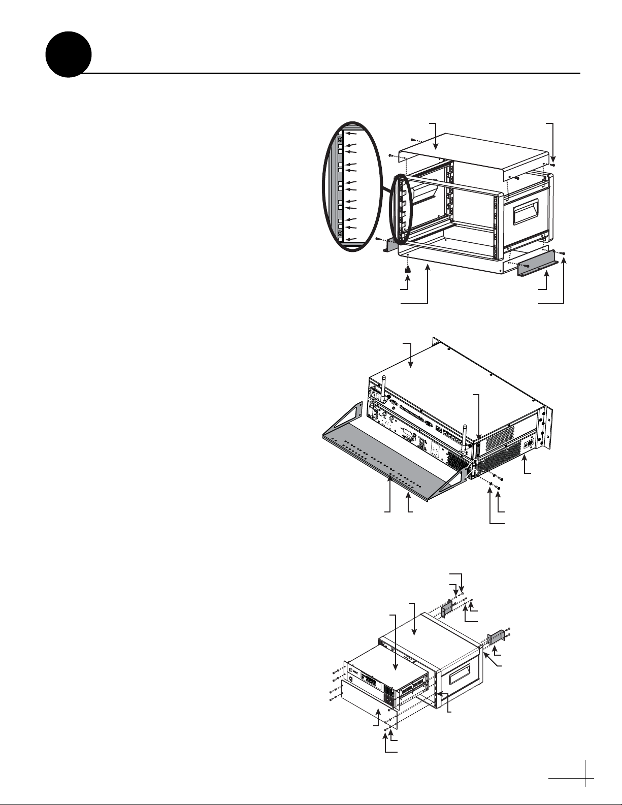
Figure 7: Assembling the Case
Figure 8: Attaching the Strain-Relief Bracket
U
Figure 9: Securing the CommBox-ACU/Modem in the Case
4
Prepare the Belowdecks Units
If you plan to use the optional case, follow these
steps to assemble the case.
a. Remove the four M4 screws securing the rear
cover to the case. Discard the rear cover.
b. Attach the top cover to the case using four
M4 x 12 mm screws (see Figure 7). Attach the
bottom cover and the two mounting brackets
using four M4 x 16 mm screws.
c. Attach the four plastic feet to the bottom
cover (see Figure 7).
d. At the front of the case, insert eight cage nuts
into the following locations on the frame
(four on each side) (see Figure 7): no. 2, no. 5,
no. 9, and no. 12.
e. At the back of the case, insert four cage nuts
into the following locations on the frame (two
on each side): no. 1 and no. 3.
f. Remove the four #6-32 screws and washers
securing the two retaining straps to the sides
of the modem. Do not remove the top screws
securing the straps to the CommBox-ACU.
Case Mount
CommBox-ACU
Retaining
Strap (x2)
g. Attach the supplied strain-relief bracket to
the retaining straps and modem using the
screws and washers you removed in Step f
(see Figure 8).
h. At the top 3U section of the case, insert the
CommBox-ACU/modem assembly and
secure the front mounting brackets to the case
using four M6 screws and washers (see
Figure 9).
i. Secure the back of the CommBox-ACU to the
back of the case using the two supplied “Z”
brackets. Attach the brackets to the case
frame using four M6 screws and washers.
Attach the brackets to the rear panel of the
CommBox-ACU using four #6-32 screws and
washers (see Figure 9).
j. At the bottom 3U section of the case, attach
the supplied blank panel using four M6
screws and washers (see Figure 9).
k. Once you have completed all system wiring,
mount the case to the vessel using fasteners
appropriate for the mounting surface.
Modem
Tie-Wrap
Holes (x42)
Attach to Case
Plastic Washer (x4)
CommBox-ACU
and Modem
Blank Panel
Strain-Relief
Bracket
M6 Screw (x4)
Case
Plastic Washer (x8)
M6 Screw (x8)
#6-32 Screw (x4)
#6 Washer (x4)
Attach to CommBox-AC
#6-32 Screw (x4)
#6 Washer (x4)
“Z” Bracket (x2)
Cage Nut (x4)
Cage Nut (x8)
7
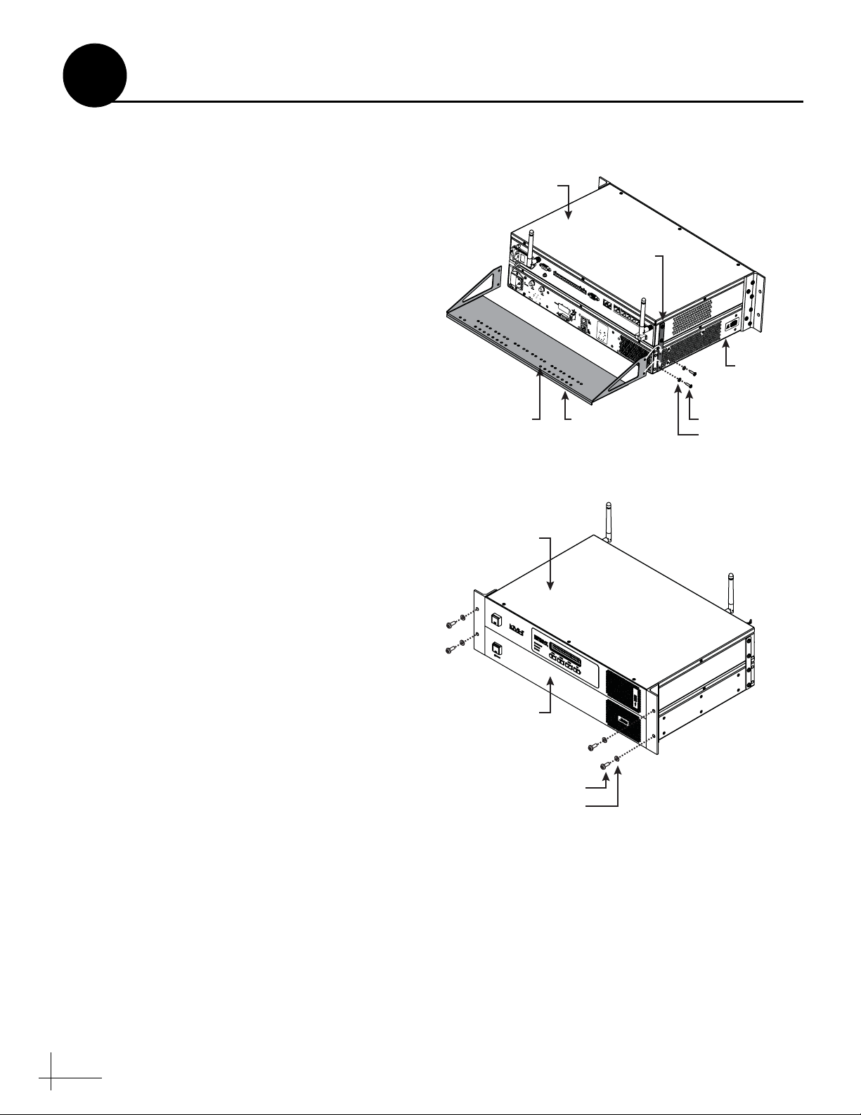
Figure 10: Attaching the Strain-Relief Bracket
Figure 11: Securing the CommBox-ACU/Modem in the Rack
4
Prepare the Belowdecks Units
If you plan to use an existing equipment rack,
follow these steps to secure the equipment in the
rack.
a. Remove the four #6-32 screws and washers
securing the two retaining straps to the sides
of the modem. Do not remove the top screws
securing the straps to the CommBox-ACU.
b. Attach the supplied strain-relief bracket to
the retaining straps and modem using the
screws and washers you removed in Step a
(see Figure 10).
c. Insert the CommBox-ACU/modem assembly
into the rack and secure the front mounting
brackets to the rack using four M6 screws and
washers (see Figure 11).
CommBox-ACU
Tie-Wrap
Holes (x42)
Retaining
Strap (x2)
Strain-Relief
Bracket
Rack Mount
Modem
#6-32 Screw (x4)
#6 Washer (x4)
CommBox-ACU
Modem
Attach to Rack
M6 Screw (x4)
Plastic Washer (x4)
8
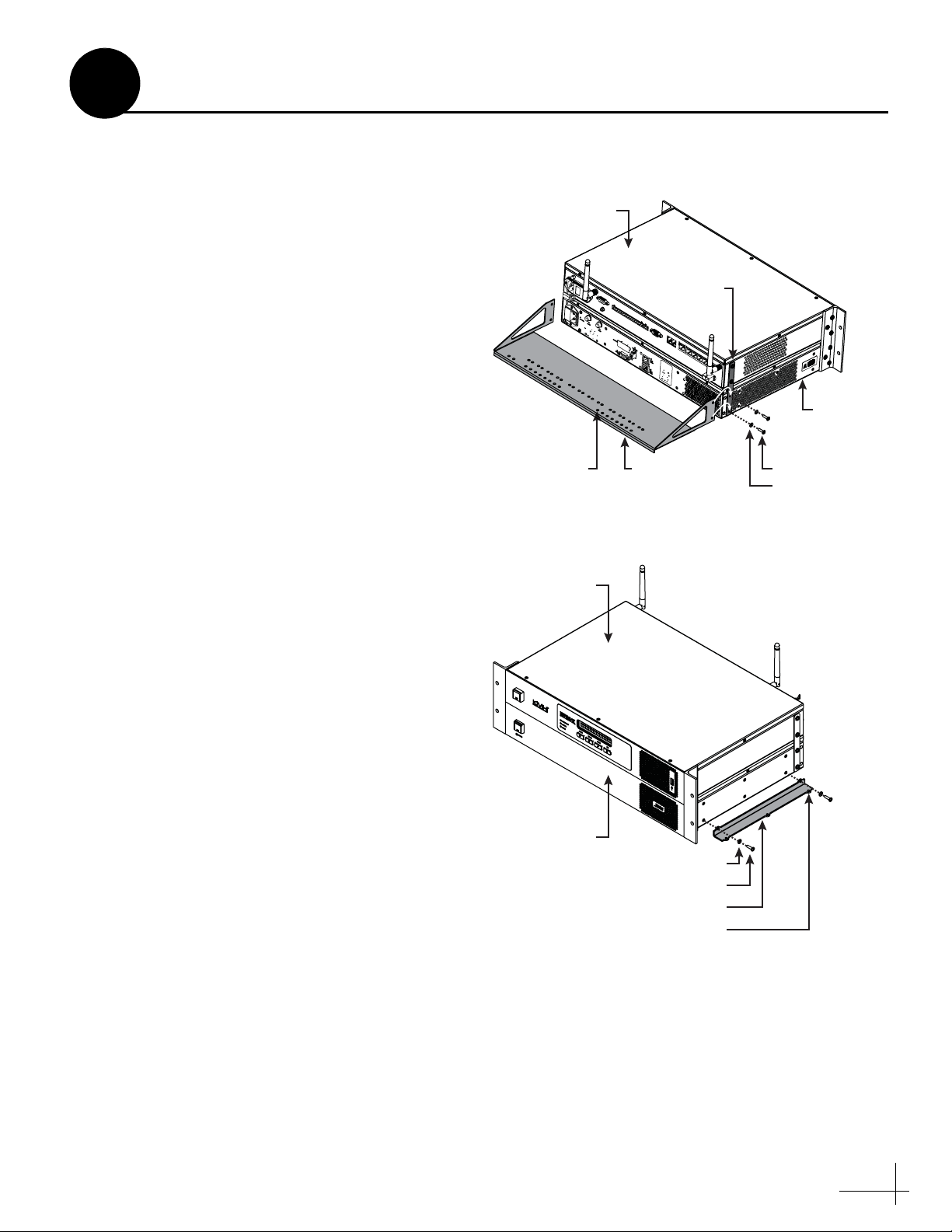
Figure 12: Attaching the Strain-Relief Bracket
Figure 13: Attaching the Mounting Brackets
#6 Washer (x4)
#6-32 Screw (x4)
Bracket (x2)
CommBox-ACU
Modem
Ø.156" (Ø3.96 mm)
Mounting Hole (x4)
4
Prepare the Belowdecks Units
If you plan to mount the CommBox-ACU and
modem to a horizontal surface, without using the
optional case or an equipment rack, follow these
steps to attach the strain-relief bracket and “L”
mounting brackets.
a. Remove the four #6-32 screws and washers
securing the two retaining straps to the sides
of the modem. Do not remove the top screws
securing the straps to the CommBox-ACU.
b. Attach the strain-relief bracket to the
retaining straps and the modem using the
screws and washers you removed in Step a
(see Figure 12).
c. Attach the supplied “L” mounting brackets to
the sides of the modem using four #6-32
screws and washers (see Figure 13).
d. Once you have completed all system wiring,
mount the modem/CommBox-ACU
assembly to the vessel using fasteners
appropriate for the mounting surface.
Horizontal Surface Mount
CommBox-ACU
Retaining
Strap (x2)
Tie-Wrap
Holes (x42)
Strain-Relief
Bracket
#6-32 Screw (x4)
#6 Washer (x4)
Modem
9
8.49"
(216 mm)
Ø.63" (Ø16 mm)
Mounting Hole (x4)
8.49"
(216 mm)
Ø3.75" (Ø95 mm)
Cable Access Hole
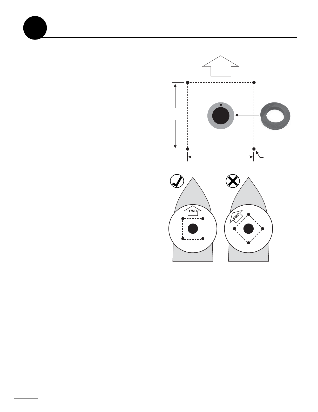
FWD
Foam Seal
Good Bolt
Pattern
Poor Bolt
Pattern
Figure 14: Antenna Mounting Holes Layout
5
Once you have identified a suitable antenna
mounting site, according to the guidelines
provided in Step 2, follow these steps to drill the
mounting holes and cable access hole to prepare
the site for installation.
a. Unfold the antenna mounting template
(supplied in the Customer Welcome Kit) and
place it onto the mounting surface. Make sure
the “FWD” (forward) arrow points toward
the bow and is parallel to the vessel’s
centerline (see Figure 14).
NOTE: You don’t need to mount the antenna exactly
on the vessel’s centerline, but the antenna’s forward
arrow must be parallel to it.
b. Using a light hammer and center punch,
mark the locations for the four mounting
holes and cable access hole on the mounting
surface in the locations indicated on the
template.
Prepare the Antenna Site
c. Drill a 5/8" (16 mm) hole at the four
d. Cut out the 3.75" (95 mm) cable access hole in
e. Clean and dry the antenna mounting surface.
f. Peel off the paper backing from the supplied
mounting hole locations you marked in
Step b. Later, you will insert four 1/2"-13
bolts through these holes to secure the
antenna to the mounting surface.
the location you marked in Step b. Smooth
the edges of the hole to protect the cables.
Later, you will route the power/data and RF
cables through this hole and into the vessel.
(You may also apply anti-chafe material
around the cables to protect them from
abrasion.)
foam seal to expose the adhesive. Then press
the foam seal down firmly onto the mounting
surface, ensuring the hole in the foam seal
aligns with the cable access hole in the
mounting surface (see Figure 14).
NOTE: Apply the foam seal to the vessel mounting
surface, not to the antenna’s baseplate. You will have
difficulty connecting the cables to the antenna if the
foam seal is attached to the baseplate.
10
 Loading...