

TracPhone V7 User’s Guide
TracPhone V7
TracPhone V7
mini-VSAT Broadbandsm System
User’s Guide
This user’s guide provides all of the basic information you need to
operate, set up, and troubleshoot the TracPhone V7 system. For
detailed installation information, please refer to the TracPhone V7
Installation Guide.
TracPhone V7 User’s Guide
Serial Numbers
Please direct questions, comments, or suggestions to:
KVH Industries, Inc. KVH Europe A/S
50 Enterprise Center Kokkedal Industripark 2B
Middletown, RI 02842-5279 USA 2980 Kokkedal, Denmark
Tel: +1 401 847-3327 Tel: +45 45 160 180
Fax: +1 401 849-0045 Fax: +45 45 160 181
E-mail: info@kvh.com E-mail: info@kvh.dk
Internet: www.kvh.com Internet: www.kvh.com
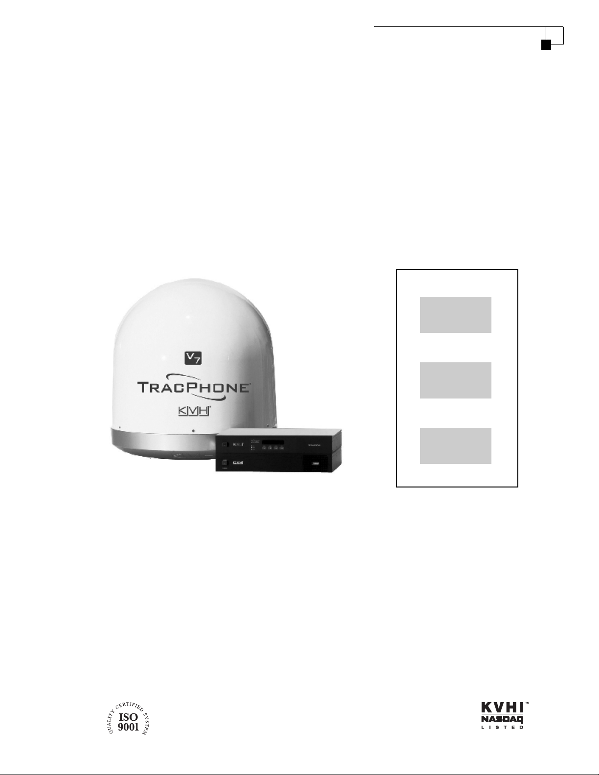
Antenna
Control Unit
Modem
If you have any comments regarding this manual, please e-mail
them to manuals@kvh.com. Your input is greatly appreciated!
KVH Part # 54-0465 Rev. A
© 2007, KVH Industries, Inc., All rights reserved.

Trademark Information
TracPhone, KVH, and the unique light-colored dome with contrasting baseplate are registered
trademarks of KVH Industries, Inc.
mini-VSAT Broadband is a service mark of KVH Industries, Inc.
SES AMERICOM is a registered trademark of SES AMERICOM.
ViaSat and the ViaSat logo are registered trademarks of ViaSat, Inc.
All other trademarks are the property of their respective owners.
Disclaimer
Every effort has been made to ensure the correctness and completeness of the material in this
document. No company shall be liable for errors contained herein. The information in this
document is subject to change without notice. No warranty of any kind is made with regard to
this material, including, but not limited to, the implied warranties of merchantability and fitness
for a particular purpose.

CE Declaration of Conformity
The undersigned declares that the following equipment complies with the specifications
of EMC Directive 1999/5/EC Radio & Telecommunications Equipment. The general
safety requirements in EMC Directive 2006/95/EC have not been tested.
Equipment Included in this Declaration
• TracPhone V7 Antenna (02-1563)
• TracPhone V7 Control Unit (02-1601)
• TracPhone V7 Modem (19-0487)
Equipment Applicability
The TracPhone V7 system provides broadband Internet connectivity and voice services
between a ship and any destination in the world. The equipment is intended to be used
on non-SOLAS vessels outside of GMDSS.
Declaration and Certification
KVH declares that the protection requirements with respect to the EMC Directive
2004/108/EC, and the effective use of spectrum as shown by 301-427, are fulfilled in
conformity with the following standards:
• EN 301 427 V1.2.1
• EN 301 843-1 V1.2.1
• EN 301 843-6 V1.1.1
• EN 61000-3-2:2000
• EN 61000-3-3:1995
• EN 60945:2002
Manufacturer
KVH Industries, Inc.
50 Enterprise Center
Middletown, RI 02842 USA
Authority
Brian Arthur, Director of Program Management Date

Table of Contents
1Introduction
Using this Manual ..............................................................................3
Important Safety Information.............................................................5
System Overview ...............................................................................6
2Operation
Satellite Communication Basics ......................................................11
TracPhone V7 User’s Guide
Table of Contents
Turning On the System ....................................................................12
System Startup ................................................................................13
Using the mini-VSAT Broadband Service.........................................14
Using KVH’s Enhanced VoIP Service ................................................15
3 Configuration
Adjusting the Control Unit Display Brightness .................................21
Configuring RF Radiation Hazard Zones ..........................................23
Resetting the System to Factory Conditions....................................31
Configuring Your Computer for mini-VSAT Broadband ....................33
4 Troubleshooting
Five Simple Checks..........................................................................43
Control Unit Status Lights ................................................................44
Modem Status Light.........................................................................46
Error Messages................................................................................47
Troubleshooting an Enhanced VoIP Service Problem ......................50
Viewing Status Information on Your Web Browser ..........................51
Viewing Status Information on the Control Unit...............................57
i

TracPhone V7 User’s Guide
Table of Contents
A Wiring Diagram
B Menus Quick Reference Guide
CGlossary
Calibrating the Antenna Gyros .........................................................63
Technical Support............................................................................65
Wiring Diagram ................................................................................69
Menus Quick Reference Guide.........................................................73
Glossary ...........................................................................................77
ii

1. Introduction
This chapter provides a basic overview of this manual and your
TracPhone system. It also provides important safety information you
need to know before using the product.
Contents
Using this Manual.............................................................. 3
Important Safety Information ............................................ 5
System Overview............................................................... 6
TracPhone V7 User’s Guide
Chapter 1 - Introduction
1
Using this Manual
This manual provides complete operation, configuration, and
troubleshooting information for your TracPhone V7 system.
Who Should Use this Manual
The user should refer to the “Operation” chapter to learn how to
operate the system.
The user or installer should refer to the “Configuration” chapter for
information on setting up the system for the desired preferences.
The user and/or servicing technician should refer to the
“Troubleshooting” chapter to help identify the cause of a system
problem.
TracPhone V7 User’s Guide
Chapter 1 - Introduction
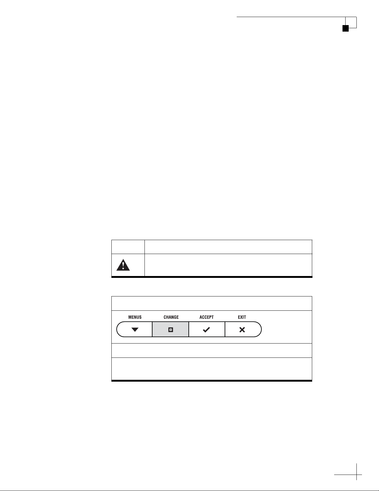
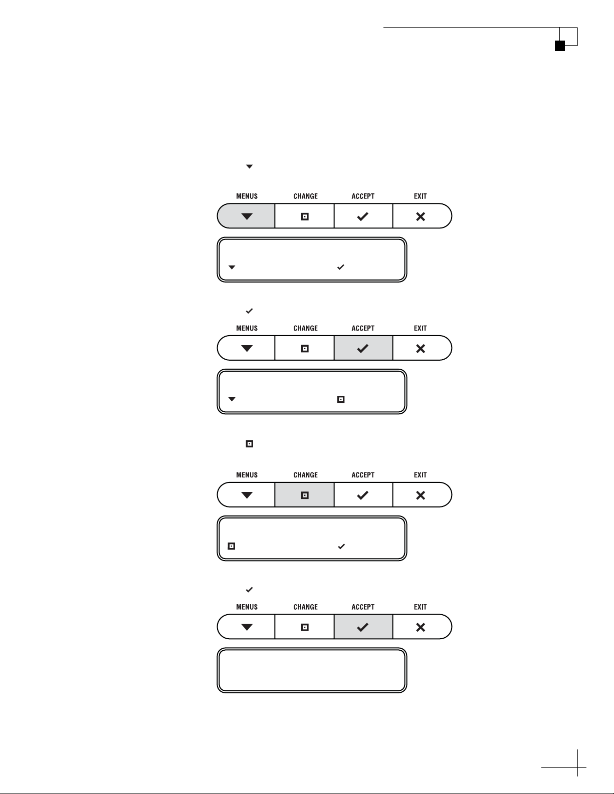
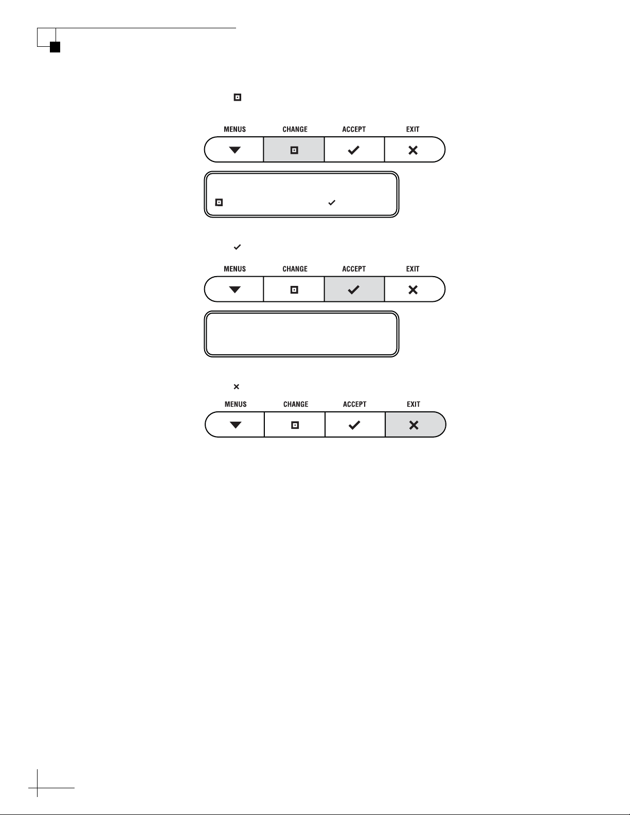
Icons Used in this Manual
This manual uses the following icons:
Icon Description
Icon
Description
This is an illustration of the buttons on the control unit. Gray
shading indicates which button the user should press.
This is a danger, warning, or caution notice. Be sure
to read these carefully to avoid injury!
3

TracPhone V7 User’s Guide
Chapter 1 - Introduction
Typographical Conventions
This manual uses the following typographical conventions:
Text Example Description
Press MENUS to view
the menu
SELECT SATELLITES Text as it appears on the control unit
The display shows
“BRIGHTNESS”
See “Switching Satellites”
on page 14.
Related Documentation
In addition to this User’s Guide, the following documents are
provided with your TracPhone system:
Document Description
Installation Guide Complete installation instructions
Both the icon and the name of the
button are provided
display
Text in quotes is shown on the
control unit display
Cross-reference to another chapter in
the manual or to a website
Service Activation Form Details on activating the system for
mini-VSAT Broadband service
Antenna Mounting
Template
Warranty Statement Warranty terms and conditions
Contents List List of every part supplied in the kit
4
Template that the installer uses to lay
out the antenna mounting holes
Important Safety Information
For your own safety, and for the safety of your passengers and/or
crew, be sure to read the following important notices.
Warning - Risk of Electric Shock
Potentially lethal voltages are present within the control unit and the
modem. To avoid electric shock, do not open the chassis enclosures of
the belowdecks equipment. They contain no user-serviceable parts,
and opening the enclosure(s) will void the product’s warranty.
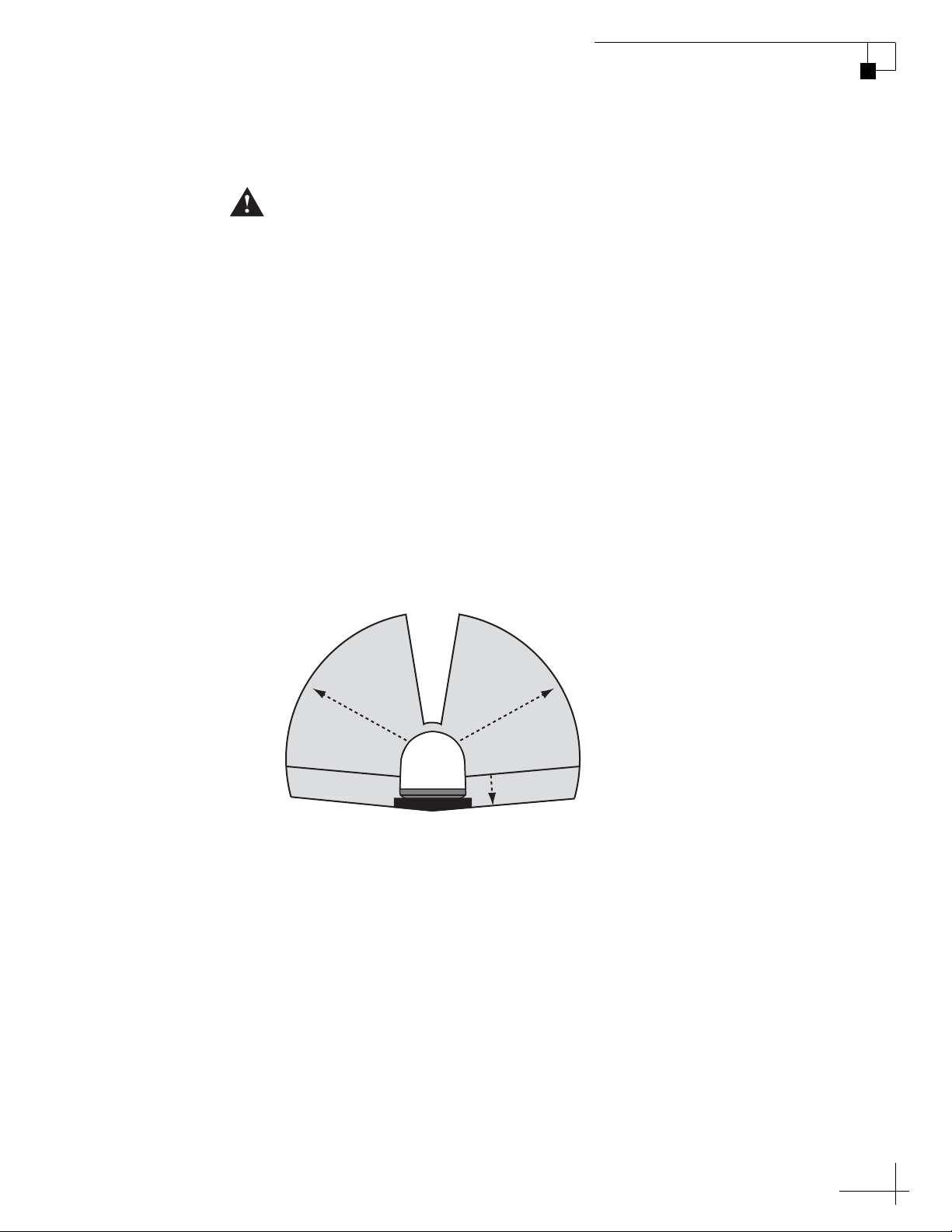
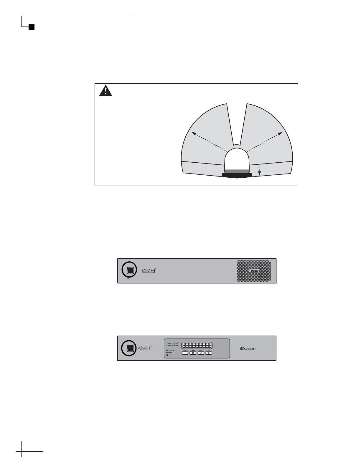
Caution - RF Radiation Hazard
The antenna transmits radio frequency (RF) energy that is potentially
harmful. Whenever the system is powered on, make sure all personnel
stay more than 36 feet (11 m) away from the antenna within its 5°-80°
elevation range. No hazard exists 2 feet (0.6 m) directly above the
antenna and 2 feet (0.6 m) below the antenna’s centerline.
TracPhone V7 User’s Guide
Chapter 1 - Introduction
Figure 1-1 Safe Distances from the Antenna to Avoid Risk of RF Radiation Exposure
Radiation
Hazard
3
6
ft
(1
1
m)
Antenna
Radiation
Hazard
(1
t
f
6
3
2 ft (0.6 m)
1
m)
NOTE: Using the control unit, you can set up RF radiation hazard zones to
inhibit transmissions within areas frequented by your passengers and/or
crew. See “Configuring RF Radiation Hazard Zones” on page 23 for
details.
5
TracPhone V7 User’s Guide
Chapter 1 - Introduction
System Overview
Your TracPhone V7 is a complete mini-VSAT Broadband
communications system for mariners on the move. Using cutting-edge
spread spectrum technology, which was previously only available to
the military and corporate jets, the TracPhone V7 delivers a seamless
and consistent Internet experience. And it all comes with an antenna
that is 85% smaller and 75% lighter than traditional VSAT antennas.
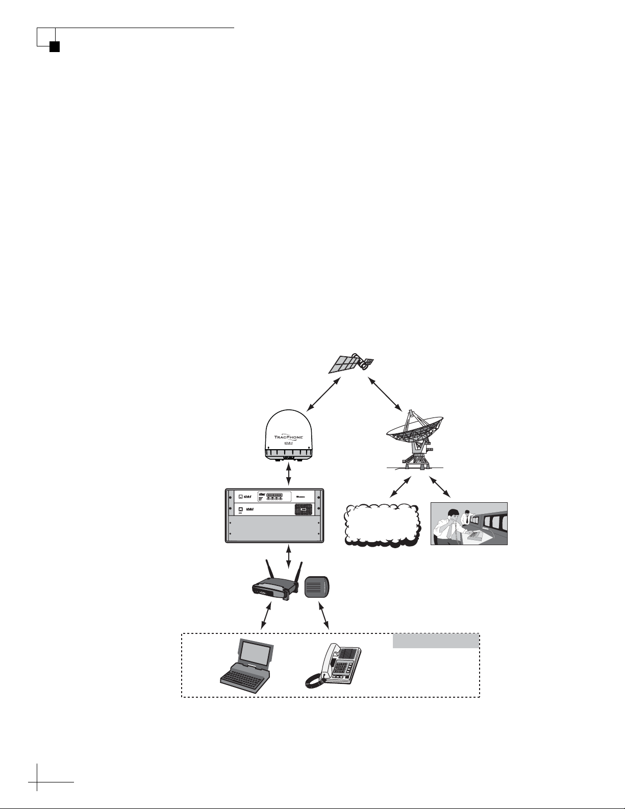
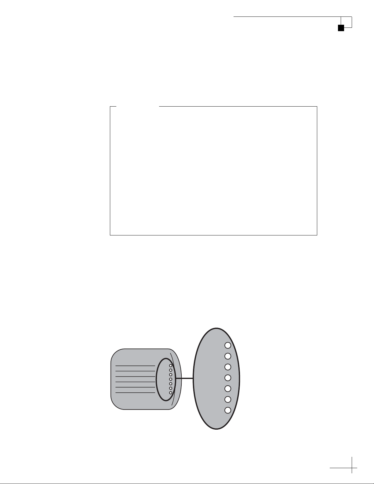
As shown in the basic diagram below, the system consists of an
antenna system, control unit, and modem that connect to a land-based
hub via a Ku-band satellite. The hub then provides the Internet link, as
managed by the Network Operations Center. A brief description of
each system component is provided on the following page. A detailed
wiring diagram is provided in “Wiring Diagram” on page 69.
Figure 1-2 TracPhone V7 mini-VSAT Network Diagram
TracPhone
Antenna
Control Unit
& Modem
Routing & VoIP
Devices
Wireless or Wired
Ethernet Connection
Laptop
PC
Ku-Band Satellite
mini-VSAT
Connection
Hub
Internet
Network Operations
Center (NOC)
VoIP Connection
Customer-Supplied
Analog
Phone
6
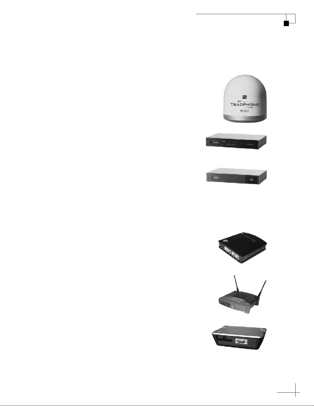
System Components
The TracPhone V7 system includes the following components:
The antenna unit provides the satellite link
between the onboard modem and the landbased hub. Using its integrated GPS,
advanced reflector technology, and gyro
stabilization, the antenna automatically
locates and tracks the correct satellite, even
while your vessel is on the move.
The control unit supplies power to the
antenna unit, links the antenna to the
modem, and allows you to operate and
configure all aspects of the system.
TracPhone V7 User’s Guide
Chapter 1 - Introduction
The modem, manufactured by ViaSat, is the
transceiver and “brain” of the system. It
processes all incoming and outgoing TCP/
IP data between the antenna and the router
using its proprietary spread spectrum
technologies. It also powers the antenna’s
transmit and receive components (BUC and
LNB).
The multimedia terminal adapter (MTA) is
a Voice over IP (VoIP) device that allows
you to connect up to two analog telephones
and make and receive calls over the miniVSAT Broadband connection.
The router links the system to your onboard
local area network (LAN) via both wireless
(WiFi) and wired Ethernet connections. It
also offers several security options,
including encryption, to protect your
wireless network from outside intrusion.
The remote service and support module is a
compact GPRS cellular modem. This unit
allows KVH Technical Support to “dial in”
to your system for troubleshooting
purposes.
7

TracPhone V7 User’s Guide
Chapter 1 - Introduction
Service Activation
Before you can start using the TracPhone V7, you need to activate the
system for mini-VSAT Broadband service. To activate, simply fill out
the Activation Form provided in your Customer Welcome Kit. Then
fax the completed form to KVH at one of the following numbers:
Once KVH processes the form, a representative will call you to
confirm your system is activated and ready for use.
North/South America, Australia:
Fax: +1 401 851-3823
Europe, Middle East, Asia:
Fax: +45 45 160 181
8

2. Operation
This chapter explains how to turn on and use the TracPhone V7 system.
It also explains how to interpret the startup screens.
Contents
Satellite Communication Basics...................................... 11
Turning On the System.................................................... 12
System Startup................................................................ 13
Using the mini-VSAT Broadband Service......................... 14
TracPhone V7 User’s Guide
Chapter 2 - Operation
Using KVH’s Enhanced VoIP Service................................ 15
9

Satellite Communication Basics
Ku-band communications satellites are located in fixed positions
above the Earth’s equator and relay data to/from the earth within the
regions that they serve. Therefore, to communicate via a given
satellite, you must be located within that satellite’s unique coverage
area, also known as its “footprint.”
TIP: To view the latest mini-VSAT Broadband satellite coverage map, visit
our website at www.kvh.com/footprint.
Figure 2-1 Example of a Satellite Footprint
TracPhone V7 User’s Guide
Chapter 2 - Operation
Equator
In addition, since satellites are located 22,300 miles (35,900 km) above
the equator, the TracPhone antenna must have a clear view of the sky
to transmit and receive signals. Anything that stands between the
antenna and the satellite can block signals, resulting in lost data.
Common causes of blockage include trees, buildings, and bridges.
Heavy rain, ice, or snow may also temporarily interrupt reception.
Figure 2-2 Example of Satellite Blockage
Blocked!
TracVision
11
TracPhone V7 User’s Guide
Chapter 2 - Operation
Turning On the System
Follow the steps below to turn on your TracPhone system.
The antenna transmits RF
energy that is potentially
harmful. All personnel
must stay more than 36 feet
(11 m) away from the
antenna within its 5°-80°
elevation range. No hazard
exists 2 feet (0.6 m) above
the antenna and 2 feet
(0.6 m) below its centerline.
CAUTION
Radiation
3
6
Hazard
f
t (
1
1
m)
Antenna
Radiation
Hazard
(1
t
f
6
3
2 ft (0.6 m)
1 m
)
1. Make sure the antenna has a clear view of the sky.
2. Make sure power is applied to the modem, control unit,
router, MTA, and computer(s).
3. Press the power button on the modem. The button’s
light should illuminate green.
Figure 2-3 Modem Front Panel Power Switch
STATUS
4. Press the power button on the control unit. The button’s
light should illuminate green. The control unit supplies
power to the antenna.
Figure 2-4 Control Unit Front Panel Power Switch
12
5. Turn on your networked computer(s).
6. Wait five minutes for system startup (see the next
section for details).
Once the antenna finds the correct service satellite, all status lights on
the control unit and the modem should be lit green. If any lights are
not lit green, refer to “Troubleshooting” on page 41.
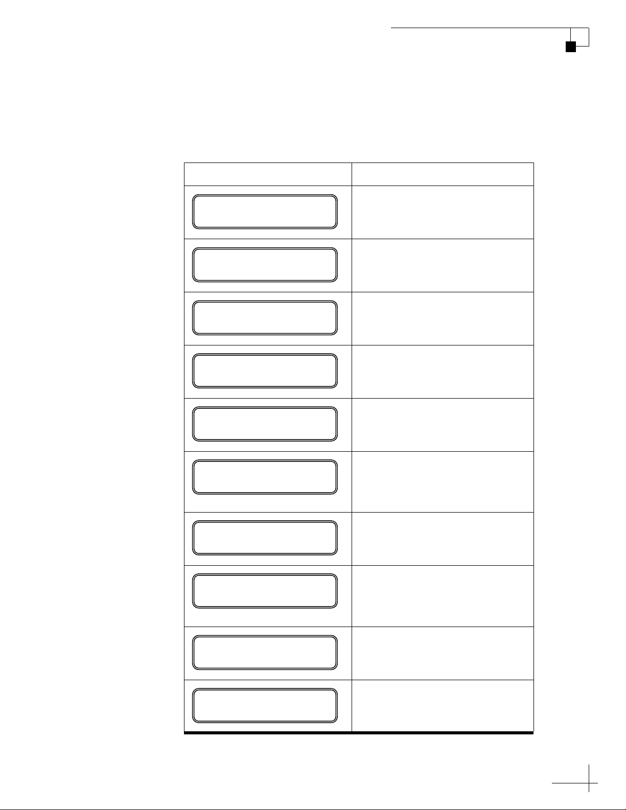
System Startup
The control unit shows the following screens during startup. If the
display shows an error message, see “Error Messages” on page 47.
Control Unit Screen Description
TracPhone V7 User’s Guide
Chapter 2 - Operation
ANTENNA INITIALIZING
GPS: ACQUIRED
41.1N, 72.3W
WAITING FOR MODEM
MODEM COMMS: OK
RECEIVING SATELLITE
INFO FROM MODEM
SEARCHING FOR 72W
DVB-ASSIST SATELLITE
Note: Satellites will vary
The antenna is running a self test
routine
When GPS acquires a fix,
momentarily displays your
latitude/longitude
The antenna is waiting for the
modem to initialize
The modem is communicating
with the control unit
The modem is providing satellite
identification data to the antenna
The antenna is searching for the
DVB-assist satellite, which helps
it find the correct service satellite
TRACKING 72W
DVB-ASSIST SATELLITE
SEARCHING FOR 22W
SERVICE SATELLITE
Note: Satellites will vary
TRACKING 22W
SERVICE SATELLITE
ONLINE
TRACKING 22W
The antenna has found the DVBassist satellite
The antenna is shifting to point at
the mini-VSAT Broadband
service satellite
The antenna is now tracking the
service satellite
The modem has accessed the
mini-VSAT Broadband service;
the system is ready for use!
13

TracPhone V7 User’s Guide
Chapter 2 - Operation
Using the mini-VSAT Broadband Service
Once the TracPhone V7 modem establishes a connection with the
mini-VSAT Broadband service, you can perform all of the same
Internet tasks you perform at home:
•E-mail
• Video conferencing
• Internet browsing
• Weather and chart updates
• Instant messaging
• Accessing corporate networks (VPNs)
• Data transfers
IMPORTANT!
Certain applications, such as continuous streaming video, web
cams, and high-speed gaming, are not supported by fixed-rate
service plans. For details, be sure to read all of the service terms
and conditions, which can be found at www.kvh.com/
Your_Account, under “mini-VSAT Broadband Documents.”
NOTE: The system must be activated before you can use it. See “Service
Activation” on page 8 for details.
14
Using KVH’s Enhanced VoIP Service
The MTA and Enhanced Voice over IP (VoIP) Service allow you to
make/receive telephone and fax calls via the mini-VSAT Broadband
service. This section explains how to use basic VoIP functions.
IMPORTANT!
The TracPhone V7 VoIP service will not provide Automatic
Number Identification or Automatic Location Information
capabilities associated with emergency 911 or E911 services. In
addition, the VoIP service will not work in the event of either a
network service outage or a power failure. Therefore, it is critical
that you maintain your vessel’s separate distress and safety
communications system for emergency calls. Be sure to inform
anyone who may use the TracPhone V7 of the limitations of 911
and E911 emergency services. The manufacturer, distributor, and
service provider shall not be liable for, and expressly disclaim, any direct
or indirect damages, claims, losses, expenses, liabilities, actions, risks, or
harms arising out of or related to the services provided through this
equipment, including without limitation, emergency 911 or E911
services.
TracPhone V7 User’s Guide
Chapter 2 - Operation
Turning On the MTA
The MTA has no on/off switch; simply make sure its power supply is
plugged into vessel AC power. When you turn on the TracPhone V7
system, the MTA initializes, which may take up to 15 minutes. The
MTA is ready once its “RUN” light is lit steady green (see Figure 2-5).
For complete details about the MTA device, refer to the MTA User’s Guide.
Figure 2-5 MTA Status Lights
POWER
VOIP
PHONE 2
PHONE 1
POWER
RUN
RUN
WAN
LAN
WAN
LAN
VOIP
PHONE 2
PHONE 1
15

TracPhone V7 User’s Guide
Chapter 2 - Operation
Placing a Voice Call
Calls originating from a TracPhone V7 system are terminated in the
United States. Therefore, to place a call, you will need to dial as if you
are calling from the U.S., regardless of your vessel’s location. Follow
the steps below to place a call via the TracPhone V7.
1. Make sure the TracPhone V7 system is turned on and
connected to the mini-VSAT Broadband service (the
control unit shows “Online”). Also make sure the
“RUN” light on the MTA is lit green.
2. Pick up the handset on any phone connected to the
MTA. You should hear a dial tone.
3. Dial the phone number you wish to call.
If you are calling within the U.S.:
Dial 1 + Area Code + Local Phone Number
If you are calling outside of the U.S.:
Dial 011 + Country Code + Area Code + Local Phone Number
For example, if the country code is 99, the city code is 77, and
the local number is 555-8888, dial 01199775558888.
NOTE: When you make a VoIP call via the mini-VSAT Broadband service,
your voice travels 22,300 miles (35,900 km) into space, then 22,300 miles
(35,900 km) back to Earth, just like any other satellite voice service. This
lengthy transit will necessarily cause a brief delay (approximately 0.5 second)
in your telephone conversations, even at the fastest speeds.
Recording a VoiceMail Personal Greeting
Follow the steps below to record your VoiceMail personal greeting.
1. Pick up the handset on any phone connected to the
MTA. You should hear a dial tone.
2. Dial 123 on the telephone keypad to connect to the
VoiceMail system.
3. Press 2 to access your mailbox.
16
4. Press 1 to access your personal greeting.
5. Press 2 to change your greeting. You will be prompted
to record your greeting.
6. Press 1 to listen to your personal greeting.
7. When you are satisfied with your greeting, press 3 to
accept and activate your greeting. You will hear the
message “Your personal greeting has been activated.”

Listening to Your VoiceMail Messages
If the “PHONE 1” or “PHONE 2” light on the MTA is blinking orange
when the telephone handset is on the hook, you have new VoiceMail
messages (see Figure 2-5 on page 15). Follow the steps below to listen
to your VoiceMail messages.
1. Pick up the handset on any phone connected to the
MTA. You should hear a dial tone.
2. Dial 123 on the telephone keypad to connect to the
VoiceMail system.
3. Press 1 to listen to your messages.
4. Follow the spoken instructions to listen to, save, and/or
delete your messages.
NOTE: You can also listen to your messages online at your VoIP account
web page (see “Managing Your VoIP Account Online” on page 18). In
addition, you can access VoiceMail from any regular landline telephone.
Simply dial the number for your main U.S. VoIP phone line, press *, then
enter your PIN (provided during service activation).
TracPhone V7 User’s Guide
Chapter 2 - Operation
Sending or Receiving a Fax
Faxing is easy via the TracPhone V7 Enhanced VoIP Service. Simply
connect a fax machine to either “PHONE” jack on the MTA and dial as
you would a voice call (see “Placing a Voice Call” on page 16).
NOTE: Faxing requires 70k bandwidth for sending and up to 90k bandwidth
for receiving. When fax and voice are used simultaneously on both MTA
ports, the bandwidth requirement increases to between 100k and 170k.
17

TracPhone V7 User’s Guide
Chapter 2 - Operation
Managing Your VoIP Account Online
You can manage your account online at your Enhanced VoIP account
web page. You can view and configure all of the various calling
features available to you, as well as view account information and
listen to VoiceMails. To log onto the site, follow the steps below:
1. Go to www.kvh.com/Your_Account.
2. At the Your Satellite Services Account web page, select
“mini-VSAT Broadband” from the drop-down menu.
3. At the login page, enter your user name and password
for the mini-VSAT Broadband service (provided during
service activation).
4. At your mini-VSAT Broadband account web page, click
the “Enhanced VoIP Account” tab in the sidebar.
5. At the login page, enter your primary VoIP phone
number and PIN (provided during service activation).
NOTE: You can also contact Customer Support by dialing 611 on your
telephone handset.
18

3. Configuration
This chapter explains how to change the brightness of the control unit’s
display, set up an RF radiation hazard zone, and reset the system to its
factory configuration. It also explains how to configure your computer
for a wired Ethernet connection to the TracPhone V7 system. For details
on setting up a wireless network, refer to the instructions provided with
the router.
Contents
Adjusting the Control Unit Display Brightness................. 21
TracPhone V7 User’s Guide
Chapter 3 - Configuration
Configuring RF Radiation Hazard Zones .......................... 23
Resetting the System to Factory Conditions.................... 31
Configuring Your Computer for mini-VSAT Broadband.... 33
19
TracPhone V7 User’s Guide
Chapter 3 - Configuration
Adjusting the Control Unit Display Brightness
Follow the steps below to adjust the brightness of the control unit’s
front panel display.
1. Press MENUS until the display shows
“CONFIGURATION.”
CONFIGURATION
NEXT MENU ACCEPT
2. Press ACCEPT.
BRIGHTNESS= HIGH
NEXT ITEM CHANGE
3. Press CHANGE until the display shows the desired
brightness setting: HIGH, MEDIUM, or LOW.
BRIGHTNESS= MEDIUM?
CHANGE ACCEPT
4. Press ACCEPT.
BRIGHTNESS= MEDIUM
21

TracPhone V7 User’s Guide
Chapter 3 - Configuration
5. Press EXIT to exit the menu.
22

Configuring RF Radiation Hazard Zones
To prevent exposure to the antenna’s radiated RF energy, you can
configure up to two RF radiation hazard zones for areas where crew
and/or passengers frequent. (See “Important Safety Information” on
page 5 for details on minimum safety distances.)
When determining the need for a hazard zone, keep in mind that the
antenna transmits within an elevation range of 5°-80º. Therefore, you
do not need to consider any areas that are 2 feet (0.6 m) below the
antenna’s centerline, since they are safe from radiation exposure. In
the example below, Location A is both within 36 feet (11 m) of the
antenna and within the operating range of the antenna. So a hazard
zone to block transmissions in this direction might be appropriate.
Location B, however, is well below the level of the antenna, so RF
radiation is not a concern.
TracPhone V7 User’s Guide
Chapter 3 - Configuration
Figure 3-1 Example of an RF Radiation Hazard Zone
RF Radiation
Hazard Zone
Antenna
335
025
B
Whenever the antenna points within an RF radiation hazard zone, the
system will disable the transmitter and the control unit will display the
following message:
A
RF RADIATION HAZARD!
TRANSMIT INHIBITED
Once the antenna points outside the hazard zone, transmission
capability will be restored.
23

TracPhone V7 User’s Guide
Chapter 3 - Configuration
Defining an RF Radiation Hazard Zone
Follow the steps below to configure an RF radiation hazard zone.
1. Determine the necessary azimuth range for the RF
hazard zone. You will need to enter the beginning and
ending azimuths that define the outer boundaries of the
zone, relative to the antenna’s forward arrow, which
should be pointing toward the bow (see Figure 3-2).
NOTE: Each RF hazard zone must span at least 5º. Therefore, be sure
to set beginning and ending azimuths at least 5º apart.
Figure 3-2 Beginning and Ending Azimuths Defining RF Radiation Hazard Zone
Beginning
Azimuth
RF Radiation
Hazard Zone
(Example)
335 025
000
Ending
Azimuth
315
225
Forward
Antenna
180
045
135
2. Press MENUS until the display shows
“CONFIGURATION.”
CONFIGURATION
NEXT MENU ACCEPT
090270
24

3. Press ACCEPT.
BRIGHTNESS= HIGH
NEXT ITEM CHANGE
4. Press MENUS until the display shows “SET
HAZARD ZONE.”
SET HAZARD ZONE= NO
NEXT ITEM CHANGE
TracPhone V7 User’s Guide
Chapter 3 - Configuration
5. Press CHANGE until the display shows “SET
HAZARD ZONE = YES.”
SET HAZARD ZONE=YES?
CHANGE ACCEPT
6. Press ACCEPT.
ZONE 1= 000-000
NEXT ITEM CHANGE
25

TracPhone V7 User’s Guide
Chapter 3 - Configuration
7. Press CHANGE. A cursor appears under the first
number in the displayed azimuth range for RF
radiation hazard zone #1.
ZONE 1= 000-000
CHANGE ACCEPT
8. Press CHANGE until the number is set to the first
digit of the beginning azimuth for zone #1. If the azimuth
value is less than 100º, set the first digit to zero.
9. Press ACCEPT. The cursor moves to the next number.
ZONE 1= 300-000
CHANGE ACCEPT
10. Repeat steps 8 and 9 to set the remaining digits of the
range of azimuths for zone #1. Once you have set the
entire range, the cursor disappears from the display.
ZONE 1= 335-025?
CHANGE ACCEPT
11. Press ACCEPT. The display shows the current
azimuth range for RF radiation hazard zone #2.
ZONE 2= 000-000
NEXT ITEM CHANGE
26

TracPhone V7 User’s Guide
Chapter 3 - Configuration
12. If you wish to set up a second RF radiation hazard
zone, repeat steps 7-11. (Be sure the second zone does not
overlap the first.) Otherwise, press MENUS. The
display shows the current setting for Transmit
Inhibition (“XMT IN ZONES”).
IMPORTANT!
Make sure “XMT IN ZONES” is set to NO, so the antenna
will not transmit whenever it points within one of your
configured RF radiation hazard zones. If “XMT IN ZONES”
is set to YES, the zones are disabled, allowing the antenna to
transmit within them.
XMT IN ZONES= NO
NEXT ITEM CHANGE
13. If the display shows “XMT IN ZONES = YES,” press
CHANGE until the display shows “XMT IN ZONES
= NO.” Then press ACCEPT.
XMT IN ZONES= NO?
CHANGE ACCEPT
14. Press EXIT to exit the menu.
27

TracPhone V7 User’s Guide
Chapter 3 - Configuration
Disabling RF Radiation Hazard Zones
If you wish to remove all restrictions on transmissions, follow the
steps below to disable your programmed RF radiation hazard zones.
This function simply disables the hazard zones; it does not delete them
from memory.
Disabling RF radiation hazard zones allows the antenna to transmit
in any direction, even if the antenna is pointing in an area accessible
to passengers and crew. Make certain that everyone stays a
minimum safe distance away from the antenna before you transmit.
Also be sure to return to this menu and restore the hazard zones
when you are done transmitting.
NOTE: You can view the currently programmed hazard zones in the control
unit’s Antenna Status menu (see “Antenna Status Information” on
page 60).
CAUTION
1. Press MENUS until the display shows
“CONFIGURATION.”
CONFIGURATION
NEXT MENU ACCEPT
2. Press ACCEPT.
BRIGHTNESS= HIGH
NEXT ITEM CHANGE
28

TracPhone V7 User’s Guide
3. Press MENUS until the display shows “SET
HAZARD ZONE.”
SET HAZARD ZONE= NO
NEXT ITEM CHANGE
4. Press CHANGE until the display shows “SET
HAZARD ZONE = YES.”
SET HAZARD ZONE=YES?
CHANGE ACCEPT
Chapter 3 - Configuration
5. Press ACCEPT.
ZONE 1= 335-025
NEXT ITEM CHANGE
6. Press MENUS until the display shows “XMT IN
ZONES.”
XMT IN ZONES= NO
NEXT ITEM CHANGE
29
TracPhone V7 User’s Guide
Chapter 3 - Configuration
7. Press CHANGE until the display shows “XMT IN
ZONES = YES.”
XMT IN ZONES= YES?
CHANGE ACCEPT
8. Press ACCEPT.
WARNING: XMT ALLOWED
IN RF HAZARD ZONES
9. Press EXIT to exit the menu.
30

Resetting the System to Factory Conditions
Follow the steps below to reset the TracPhone system to its original
factory configuration.
CAUTION
Resetting the system clears all RF radiation hazard zones. The
antenna will be able to transmit in any direction until you
reprogram the hazard zones into the antenna.
1. Press MENUS until the display shows
“CONFIGURATION.”
TracPhone V7 User’s Guide
Chapter 3 - Configuration
CONFIGURATION
NEXT MENU ACCEPT
2. Press ACCEPT.
BRIGHTNESS= HIGH
NEXT ITEM CHANGE
3. Press MENUS until the display shows “FACTORY
RESET.”
FACTORY RESET= NO
NEXT ITEM CHANGE
31

TracPhone V7 User’s Guide
Chapter 3 - Configuration
4. Press CHANGE until the display shows “FACTORY
RESET= YES.”
FACTORY RESET= YES?
CHANGE ACCEPT
5. Press ACCEPT.
RESET TO FACTORY?
ACCEPT EXIT
6. Press ACCEPT again to reset the system.
32

TracPhone V7 User’s Guide
Chapter 3 - Configuration
Configuring Your Computer for mini-VSAT Broadband
Follow the steps below to configure your computer for DHCP
addressing. This will allow your computer to communicate with the
modem via its Ethernet connection.
NOTE: If you wish to set up a wireless connection, set up and test a wired
Ethernet connection first. Then follow the wireless setup instructions
provided with the router.
IMPORTANT!
When setting up a wireless network, be sure to apply security
settings, such as encryption, to protect your network from outside
intrusion. If your network is not secure, outsiders within range of
your wireless network will be able to use your wireless connection
without your knowledge.
Windows Vista
NOTE: KVH Technical Support fully supports the three operating systems
described here: Windows Vista
Follow the steps below to configure a Windows Vista computer.
1. At the Windows Control Panel, double-click the
Network and Sharing Center icon. You can find the
Control Panel either through the Start menu or “My
Computer.”
2. At the Network and Sharing Center window, double-
click the View Status link for the Ethernet connection
you are using for mini-VSAT Broadband.
™
, Windows XP, and Macintosh® OS X.
33

TracPhone V7 User’s Guide
Chapter 3 - Configuration
3. At the Local Area Connection Status window, click
Properties. If this screen doesn’t appear, just skip to Step 4.
4. At the Local Area Connection Properties window,
select the Networking tab. Then select Internet
Protocol Version 4 and click Properties.
34

TracPhone V7 User’s Guide
Chapter 3 - Configuration
5. At the Internet Protocol Properties window, select
Obtain an IP address automatically and Obtain DNS
server address automatically. Then click OK.
6. At Local Area Connection Properties, click OK.
35

TracPhone V7 User’s Guide
Chapter 3 - Configuration
Windows XP
Follow the steps below to configure a Windows XP computer.
1. At the Windows Control Panel, double-click the
Network Connections icon. You can find the Control
Panel either through the Start menu or “My Computer.”
2. At the Network Connections window, double-click the
Local Area Connection icon for the Ethernet
connection you are using for mini-VSAT Broadband.
3. At the Local Area Connection Status window, select the
General tab. Then click the Properties button. If this
screen doesn’t appear, simply skip to Step 4.
36

TracPhone V7 User’s Guide
Chapter 3 - Configuration
4. At the Local Area Connection Properties window,
select the General tab. Then select Internet Protocol
(TCP/IP) and click Properties.
5. At the Internet Protocol (TCP/IP) Properties window,
select the General tab. Then select Obtain an IP
address automatically and Obtain DNS server address
automatically. Then click OK.
37

TracPhone V7 User’s Guide
Chapter 3 - Configuration
6. At Local Area Connection Properties, click OK.
7. Restart your computer.
38

Mac OS X
TracPhone V7 User’s Guide
Chapter 3 - Configuration
Follow the steps below to configure a Mac OS X computer.
1. At System Preferences, click the Network icon.
2. At the Network window, select the following:
•Show: Built-in Ethernet
•Configure: Using DHCP
• Leave all text boxes blank.
3. Click Apply Now.
39

4. Troubleshooting
This chapter identifies basic problems along with their possible causes
and solutions. It also explains what the status lights indicate, how to use
the diagnostic functions, and how to get technical support.
Contents
Five Simple Checks ......................................................... 43
Control Unit Status Lights................................................ 44
Modem Status Light ........................................................ 46
Error Messages ............................................................... 47
TracPhone V7 User’s Guide
Chapter 4 - Troubleshooting
Troubleshooting an Enhanced VoIP Service Problem...... 50
Viewing Status Information on Your Web Browser.......... 51
Viewing Status Information on the Control Unit............... 57
Calibrating the Antenna Gyros......................................... 63
Technical Support............................................................ 65
41

Five Simple Checks
If you are experiencing a problem with your TracPhone system, first
check the five simple things below. If these checks do not lead you to
the problem, contact a KVH-certified technician (see “Technical
Support” on page 65).
Are all lights on the control unit and modem lit green?
There are three status lights on the front panel of the control unit and
one status light on the modem. If any of these lights is not lit green, see
“Control Unit Status Lights” on page 44 and “Modem Status Light”
on page 46 for failure indications.
Are any error messages displayed on the control panel?
If the control panel is showing an error message, see “Error Messages”
on page 47 for error definitions.
TracPhone V7 User’s Guide
Chapter 4 - Troubleshooting
Is the antenna unable to find the satellite?
If the control panel shows the antenna is continuously searching for
the satellite, check the area around the antenna for blockage. The
antenna requires an unobstructed view of the sky to receive satellite
signals. Common causes of blockage include trees, buildings, bridges,
mountains, and nearby equipment on the vessel itself. You can find
which direction the antenna is pointing by viewing the “AZ/EL”
status on the control unit; see “Antenna Status Messages” on page 61.
Are all system components powered on and connected properly?
Make sure power is applied to all system components, including the
modem, control unit, router, and MTA. Also make sure all of the
interconnecting cables are connected tightly.
Are you able to access the Internet via a wired connection?
Try connecting your computer directly to the router via a standard
(straight-through, not crossover) Ethernet cable, then restart your
computer. If you can then access the Internet, there is a problem with
your wireless network setup. Some possible causes include:
• Router is installed in a poor location for WiFi reception
• Security settings on the computer do not match the router’s
• The wireless connection is disabled on the computer
43

TracPhone V7 User’s Guide
Chapter 4 - Troubleshooting
Control Unit Status Lights
Three status lights on the front of the control unit indicate the current
status of the system and can help you identify problems quickly.
Figure 4-1 Control Unit Status Lights
During normal operation, all three status lights should be lit green.
The following tables explain what the different light conditions
indicate.
CONTROL UNIT Light
The table below explains what the CONTROL UNIT light indicates.
Light is... Indicates Description
Off Off Control unit is powered off or no
Green OK Good input power; control unit is
Orange Bad power Insufficient input power
Red Fault Error detected during control unit self
power input
operational
test
44

ANTENNA Light
The table below explains what the ANTENNA light indicates.
TracPhone V7 User’s Guide
Chapter 4 - Troubleshooting
Light is... Indicates Description
Off Off No power input to the antenna
Green Tracking Antenna is tracking the satellite
MODEM Light
Green,
flashing
Orange No comms Antenna has lost communications
Red Fault Error detected; see error message on
The table below explains what the MODEM light indicates.
Light is... Indicates Description
Off Off Modem powered off
Green Online Modem online and logged into the
Green,
flashing
Searching Antenna is searching for the satellite
with the modem
display
mini-VSAT Broadband service
Comms OK Modem is communicating with the
antenna
Orange Offline Modem offline; see error message on
display
Red No comms Control unit has lost communications
with the modem
45

TracPhone V7 User’s Guide
Chapter 4 - Troubleshooting
Modem Status Light
A status light on the front of the modem indicates the current status of
the modem and can help you identify problems.
Figure 4-2 Modem Status Light
STATUS
During normal operation, the status light should be lit green. The
following table explains what the different light conditions indicate.
Light is... Indicates Description
Off Off Modem is powered off or no power
input
Green Online Modem is logged into the mini-VSAT
Broadband network
Green,
Transmitting Modem is transmitting data
flashing
Red Fault Error detected in modem
46

Error Messages
The table below lists error messages that might appear on the control
unit display to indicate a system problem. Many of these faults should
only be repaired by a KVH-certified technician. For details on finding
a KVH-certified technician, see “Technical Support” on page 65.
Error Message Description
TracPhone V7 User’s Guide
Chapter 4 - Troubleshooting
WAITING FOR GPS
ERROR:
GPS FAILURE
OFFLINE
OUTSIDE COVERAGE
The system is not yet receiving
valid position data from the GPS.
It might take a few minutes for
the GPS to acquire a fix. If this
message does not clear, check for
antenna blockage. You can also
trying turning the control unit off,
then back on.
The GPS is not communicating
with the control unit. The GPS
module inside the antenna might
need to be replaced. Contact a
KVH-certified technician.
Your vessel is located outside the
mini-VSAT Broadband coverage
area, where service is unavailable
(or you are located within a
governmentally restricted area).
Service will be restored once you
reenter the coverage area.
TRANSMIT INHIBITED
BY CTRL UNIT
RF RADIATION HAZARD!
TRANSMIT INHIBITED
ERROR:
ANTENNA AZ ASSEMBLY
The transmitter is temporarily
disabled due to severe sea
conditions.
The antenna is pointing within
one of your programmed RF
radiation hazard zones. See
“Configuring RF Radiation
Hazard Zones” on page 23 for
details.
The antenna’s azimuth motor or
limit switch failed. Contact a
KVH-certified technician.
47

TracPhone V7 User’s Guide
Chapter 4 - Troubleshooting
Error Message Description
ERROR:
ANTENNA EL ASSEMBLY
ERROR:
ANTENNA SKEW ASSMBLY
ERROR:
CTRL UNIT PWR SUPPLY
ERROR:
ANTENNA POWER SUPPLY
ERROR:
ANTENNA POWER SHORT
ERROR:
ANTENNA POWER OPEN
The antenna’s elevation motor or
limit switch failed. Contact a
KVH-certified technician.
The antenna’s skew motor or limit
switch failed. Contact a KVHcertified technician.
The control unit is not supplying
enough power to the antenna.
Contact a KVH-certified
technician.
The antenna’s power supply
might have failed. Contact a
KVH-certified technician.
There is a short circuit in the
antenna power cable. Check the
cable.
There is an open circuit in the
antenna power cable. Check the
cable.
ERROR:
BUC POWER SHORT
ERROR:
BUC POWER OPEN
ERROR:
MODEM OVERTEMP
There is a short circuit in the BUC
power cable (between the control
unit and the modem) or the
transmit (TX) RF cable. Check the
cables.
There is an open circuit in the
BUC power cable (between the
control unit and the modem) or
the transmit (TX) RF cable. Check
the cables.
The modem is disabled because
its temperature has risen above
85ºC. Turn off the system and
allow it to cool down. You might
need to relocate the unit to an area
that provides better ventilation.
48

Error Message Description
TracPhone V7 User’s Guide
Chapter 4 - Troubleshooting
ERROR:
CTRL UNIT OVERTEMP
ERROR:
ANTENNA OVERTEMP
ERROR:
MODEM COMM FAILURE
ERROR:
NO LNB POWER
The control unit has stopped
supplying antenna and BUC
power because its temperature
has risen above 85ºC. Turn off the
system and allow it to cool down.
You might need to relocate the
unit to an area that provides
better ventilation.
The antenna is disabled because
its temperature has risen above
85ºC. Turn off the system and
allow it to cool down.
The control unit has lost
communications with the modem.
Ensure the modem is powered on
and check the interconnecting
cables.
The antenna’s LNB (low noise
block) is not receiving 12-18 VDC
from the modem’s “Rx RF” port.
Check the RX RF cable.
WARNING:
BAD DVB-ASSIST INFO
WARNING:
MODEM LAN LINK DOWN
CABLE UNWRAP
PLEASE WAIT
The modem is not providing valid
data for identifying the DVBassist satellite. Contact a KVHcertified technician.
The modem does not detect a
local area network (LAN) on its
“User Enet” port. Make sure the
MTA is connected to the modem
via a straight-through, not
crossover, cable.
The antenna is unwrapping its
internal cable; wait 30 seconds.
49

TracPhone V7 User’s Guide
Chapter 4 - Troubleshooting
Troubleshooting an Enhanced VoIP Service Problem
If you can access the Internet via the TracPhone system, but you are
unable to make a VoIP call, try the five simple steps below.
Make Sure You Are Dialing the Number Properly
As explained in “Placing a Voice Call” on page 16, you need to dial the
appropriate prefix(es) in addition to the local phone number in order
to complete the connection. If you are calling a U.S. phone number,
you need to dial 1 + Area Code + Local Phone Number. If you are
calling a number outside the U.S., you need to dial 011 + Country
Code + Area Code + Local Phone Number.
Reboot the MTA
The MTA might need to download an updated configuration file from
the VoIP network. Unplug the power cord from the MTA. Then plug it
back in and wait for the device to initialize (it may take 15 minutes for
the MTA to download the necessary configuration files). Once the
“RUN” light on the MTA is lit steady green, try placing your call
again.
Verify the MTA Obtained an IP Address
The MTA must receive an IP address from the modem in order to
provide a VoIP connection. Pick up the handset on any phone
connected to the MTA and press ***1 on the keypad. If you hear
“0.0.0.0” in the handset, the MTA did not receive a valid IP address.
Contact KVH Technical Support for assistance (see “Technical
Support” on page 65).
Connect a Different Phone
Disconnect the phone from the MTA and connect another phone in its
place (use a phone that you know is working properly). If you are then
able to place a call with the new phone, the phone you were using is
faulty.
Verify the Phone Is Connected Properly
Make sure your phone is connected to one of the RJ11 “PHONE” jacks
on the MTA (“PHONE 1” is the primary port). Also verify that the
MTA is connected to vessel AC power and all system wiring is correct.
50

TracPhone V7 User’s Guide
Chapter 4 - Troubleshooting
Viewing Status Information on Your Web Browser
Complete system status information is available via the modem’s local
web interface. Simply open the web browser on any networked
computer and enter the following web address:
http://192.168.0.1
You will then need to enter the following user name and password:
User name: KVH (all caps)
Password: Leave blank
As long as the modem is connected and functioning properly, a system
status page will display in your browser.
Figure 4-3 System Status Page Via Modem Web Interface
51

TracPhone V7 User’s Guide
Chapter 4 - Troubleshooting
The System Status page provides the following information:
Status Message Description
MBS System Status
• Online - Modem is connected to
the mini-VSAT Broadband
service
• Offline - Modem is not
connected to the service
Antenna State General status of the antenna:
• Tracking - Tracking the service
satellite
• Signal Acquisition - Searching
the sky for the service satellite
• Offline - Initializing
• Tracking - Tx Inhibit - Tracking
the service satellite, but
inhibited from transmitting due
to either an RF hazard zone or
location within a restricted area
• Error: ACU Fault - Error
detected in the antenna or
control unit
Satellite Location Longitude of the currently
tracked satellite
Modem State Should be “Logged In” when the
modem is online
Signal Quality Must be greater than 2 dB for
proper operation
For additional antenna status information, click the link for “detailed
antenna status” and refer to “Detailed Antenna Status” on page 53.
For additional modem status information, click the link for “detailed
modem status” and refer to “Detailed Modem Status” on page 55.
52
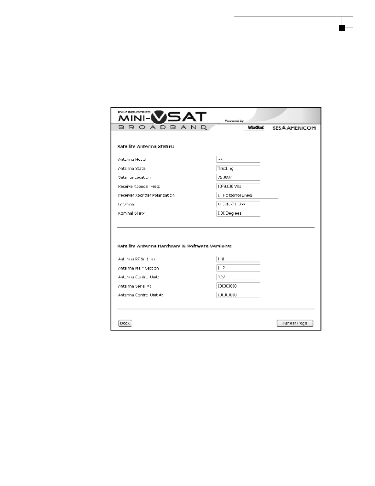
Detailed Antenna Status
When you click the link for “detailed antenna status,” the following
web page is displayed.
Figure 4-4 Detailed Antenna Status Page
TracPhone V7 User’s Guide
Chapter 4 - Troubleshooting
53

TracPhone V7 User’s Guide
Chapter 4 - Troubleshooting
The Detailed Antenna Status page provides the following information:
Status Message Description
Antenna Model TracPhone V7
Antenna State Same as System Status page
Satellite Location Same as System Status page
Receive Xponder Freq Frequency of the satellite
downlink (in MHz)
Receiver Xponder
Polarization
Polarization of the satellite
downlink:
•Horizontal Linear
•Vertical Linear
Location Vessel position reported by the
antenna’s GPS
Nominal Skew LNB skew angle
Antenna RF Section Antenna RF software version
Antenna Main Section Antenna main software version
Antenna Control Unit Control unit software version
Antenna Serial # Antenna serial number
Antenna Control Unit # Control unit serial number
54

Detailed Modem Status
When you click the link for “detailed modem status,” the following
web page is displayed.
Figure 4-5 Detailed Modem Status Page
TracPhone V7 User’s Guide
Chapter 4 - Troubleshooting
55

TracPhone V7 User’s Guide
Chapter 4 - Troubleshooting
The Detailed Modem Status page provides the following information:
Status Message Description
Serial Number Modem serial number
Modem Satellite IP External IP address of the modem;
Modem Software Version Modem software version
Terminal Uptime Length of time (in days:minutes:
# of Successful Logins Number of times the modem has
identity of the modem on miniVSAT Broadband network
hours:seconds) that the modem
has been in operation since its last
restart
logged into the network
# of Login Attempts Number of times the modem has
attempted to log into the network
Bulletin Board Messages
Received
Number of bulletin board
messages the modem has received
from the hub
Terminal State Should be “Transmit Enabled”
when tracking the service satellite
Chassis Temp Temperature of the modem’s
chassis (in ºC)
Receiver AGC Value Receiver gain; RF level indication
Eb/No Quality of the received digital
signal; should be greater than 2 dB
Link State Should be “Locked” when
tracking the service satellite
IP Packets Received Data received by the modem
EIRP Output power of the antenna
56
Attenuator Set by the hub; should be greater
than 12 dB
Errors Dropped data packets; should not
be incrementing in large numbers
IP Packets Transmitted Data transmitted by the modem

TracPhone V7 User’s Guide
Chapter 4 - Troubleshooting
Viewing Status Information on the Control Unit
If you are unable to view the status information screens on the
modem’s web interface, you can also view system status information
on the control unit’s display. You can select either modem or antenna
status information from the main menu.
Modem Status Information
1. Press MENUS until the display shows “MODEM
STATUS.”
MODEM STATUS
NEXT MENU ACCEPT
2. Press ACCEPT to start viewing the modem status
screens.
PRESS TO VIEW
EACH MODEM ITEM
MODEM STATE
ONLINE
3. Press MENUS to scroll forward through the status
messages. Press CHANGE to scroll backward. When
you are done reviewing status messages, press EXIT.
57

TracPhone V7 User’s Guide
Chapter 4 - Troubleshooting
Modem Status Messages
The table below lists all of the modem status messages.
Status Message Description
MODEM STATE
ONLINE
ETHERNET LAN STATUS
LINK OK
SERVICE SATELLITE
72.5W
DOWNLINK FREQUENCY
11.840 GHZ
General status of the modem:
• Online - Modem is connected
to the mini-VSAT Broadband
service
• Offline - Modem is not
connected to the service
• Initializing
• Attempting Login
• Waiting for Hub Comm
•Transmit Disabled
Status of the Ethernet local area
network (LAN) connection:
•Link OK
•Link Down
Satellite currently selected for
mini-VSAT Broadband service
Frequency of the satellite
downlink (in GHz)
58
DOWNLNK POLARIZATION
HORIZONTAL
EB/NO
8.6 Db
MODEM SATELLITE IP
10.61.4.9
Polarization of the satellite
downlink:
•Horizontal Linear
•Vertical Linear
Quality of the received signal;
Eb/No = Energy per bit/noise
power per Hertz; must be greater
than 2 dB for operation
External IP address of the
modem; identity of the modem on
the mini-VSAT Broadband
network (10.61.4.0 - 10.61.7.255)

Status Message Description
TracPhone V7 User’s Guide
Chapter 4 - Troubleshooting
MODEM LAN IP
192.168.0.1
MODEM SUBNET MASK
255.255.255.0
MODEM DHCP STATUS
ENABLED
MODEM TEMPERATURE
50C
Local IP address of the modem on
the vessel’s LAN
Subnet mask of the vessel’s LAN
that is connected to the modem
Status of the modem’s DHCP
server:
• Enabled - Modem is assigning
IP addresses to clients on the
LAN
• Disabled - IP addresses must be
assigned manually to each
client on the LAN
Temperature of the modem
chassis
MODEM SERIAL #
4.9
MODEM SW VERSION
r12_34
Modem serial number
Modem software version
59

TracPhone V7 User’s Guide
Chapter 4 - Troubleshooting
Antenna Status Information
1. Press MENUS until the display shows “ANTENNA
2. Press ACCEPT to start viewing the antenna status
STATUS.”
ANTENNA STATUS
NEXT MENU ACCEPT
screens.
PRESS TO VIEW
EACH ANTENNA ITEM
ANTENNA STATE
TRACKING
3. Press MENUS to scroll forward through the status
messages. Press CHANGE to scroll backward. When
you are done reviewing status messages, press EXIT.
60

Antenna Status Messages
The table below lists all of the status messages.
Status Message Description
TracPhone V7 User’s Guide
Chapter 4 - Troubleshooting
ANTENNA STATE
TRACKING
CURRENT SATELLITE
72.5W
AZ/EL TO SATELLITE
AZ:234.5, EL:67.2
SATELLITE SKEW
-78.4
General status of the antenna:
•Tracking
•Searching
• Initializing
• Waiting for Modem
• Cable Unwrap - Unwrapping
the internal cable; the cable can
wrap up to 720º
•Idle
•Error
Satellite the antenna is currently
tracking
Azimuth and elevation to the
service satellite, relative to the
antenna’s “Forward” arrow (bow)
LNB skew angle required to
receive linear satellite signals
GPS STATUS
41.2N, 123.5W
RF HAZARD ZONE 1
335-025
RF HAZARD ZONE 2
225-265
XMT IN ZONES
NO
Status of the antenna’s GPS:
• Position data - Latitude/
longitude reported by the GPS
•Acquiring
•Comm Failure
Current setting for RF hazard
zone #1
Current setting for RF hazard
zone #2
Current setting for XMT in Zones:
• No - Transmission is inhibited
if antenna points within a zone
• Yes - Transmission unrestricted
61

TracPhone V7 User’s Guide
Chapter 4 - Troubleshooting
Status Message Description
ANTENNA DC INPUT
41.2 VDC
CTRL UNIT DC INPUT
13.4 VDC
BUC POWER ON
18.4 VDC
ANTENNA MODEL
TRACPHONE V7
ANTENNA SERIAL #
070901234
ANTENNA MAIN BOARD
SW VERSION 2.34
DC voltage measured at the
antenna’s circuit board
DC voltage measured at the
control unit’s power input
Status of the antenna’s BUC
(transmit) power:
• On - BUC power is applied; also
reports actual measured power
• Off - BUC power is disabled
Antenna model
Antenna serial number
Main software version
ANTENNA RF BOARD
SW VERSION 1.23
ANTENNA AZ/EL MOTOR
SW VERSION 1.28
ANTENNA SKEW MOTOR
SW VERSION 1.04
CTRL UNIT SERIAL #
070902147
CTRL UNIT
SW VERSION 2.14
RF software version
Azimuth/elevation motor
software version
Skew motor software version
Control unit serial number
Control unit software version
62

Calibrating the Antenna Gyros
The TracPhone antenna’s gyros continuously measure the motion of
your vessel and send this data to the antenna’s motor control circuitry
to keep the antenna pointed at the satellite. At the factory, each
antenna gyro is precisely calibrated to work with the antenna’s circuit
board. Therefore, if you ever have a gyro or circuit board replaced, you
will need to recalibrate the gyros for the new part.
IMPORTANT!
Calibrate the gyros only if directed by KVH Technical Support, and
only while the vessel is stationary. A poor gyro calibration can
reduce the performance of the antenna.
Follow the steps below to calibrate the gyros.
TracPhone V7 User’s Guide
Chapter 4 - Troubleshooting
1. Press MENUS until the display shows
“DIAGNOSTICS.”
DIAGNOSTICS
NEXT MENU ACCEPT
2. Press ACCEPT to enter the Diagnostics menu.
ENTERING DIAGNOSTICS
CAL GYRO= NO
NEXT ITEM CHANGE
63

TracPhone V7 User’s Guide
Chapter 4 - Troubleshooting
3. Press CHANGE until the display shows “CAL
GYRO= YES.”
CAL GYRO= YES?
CHANGE ACCEPT
4. Press ACCEPT to start gyro calibration.
DO NOT MOVE VESSEL
DURING CALIBRATION
CALIBRATING GYROS
AZ: EL: SKEW:
5. Verify that the azimuth (AZ), elevation (EL), and skew
gyros all pass (“P”). If any gyro fails (“F”), retry the
calibration. If it continues to fail, please seek technical
support (see “Technical Support” on page 65).
CALIBRATING GYROS
AZ:P EL:P SKEW:P
6. Once the gyros are calibrated, the antenna restarts. Wait
five minutes for system startup.
64

Technical Support
The TracPhone V7 system is a sophisticated electronic device; only
specially trained KVH-certified technicians have the tools and
expertise necessary to diagnose and repair a system fault. Therefore, if
you experience an operating problem or require technical assistance,
please call or visit your local authorized TracPhone V7 dealer or
distributor. You can find a certified technician near you by visiting our
website at www.kvh.com/wheretogetservice.
If you need help finding an authorized technician, please contact KVH
Technical Support:
North/South America, Australia:
Phone: +1 401 847-3327
E-mail: techs@kvh.com
TracPhone V7 User’s Guide
Chapter 4 - Troubleshooting
Europe, Middle East, Asia:
Phone: +45 45 160 180
E-mail: support@kvh.dk
Please have your system serial numbers handy before you call. You
can get these serial numbers from the control unit’s Modem Status and
Antenna Status menus.
65

Appendix A Wiring Diagram
This appendix provides a system wiring diagram. For detailed
installation instructions, refer to the Installation Guide
Contents
Wiring Diagram................................................................ 69
TracPhone V7 User’s Guide
Appendix A - Wiring Diagram
.
67

Wiring Diagram
Antenna
MRx
Power
TracPhone V7 User’s Guide
Appendix A - Wiring Diagram
Terminal Strip Connector
12 1110987612543
Note: Terminals #3
and #8 are not used
Red
Black
MTx
Control Unit
Power
Data
White/Gray
Gray/White
White/Orange
Orange/White
White/Brown
Brown/White
White/Blue
Blue/White
SerialGP10
Service Module
Power
Antenna On/Off Audio
SIM
Power
Modem
Power
Router
Reset
J1
AC PWRJ3Rx RFJ2Tx RF
MODEL: VMBR-1510 ArcLight
PART: 1234567 REV XXX
SERIAL: XX-XXXXXX
CAGE CODE: 12345
Power
Internet 1 2 3 4
BUC PWR
J5
CONSOLE
J4
ACU
MTA
12V DC RSTR WAN LAN PHONE 2 PHONE 1
Power
J6
Power
J8
USER
CAUTION
ENET
NO OPERATOR
SERVICEABLE
J7
PARTS INSIDE,
ACU
DO NOT OPEN
ENET
Not Used
Analog
Phone
Laptop
PC
69

TracPhone V7 User’s Guide
Appendix B - Menus Quick Reference Guide
Appendix B Menus Quick Reference Guide
This appendix provides a quick reference guide to the control unit
menus
Contents
Menus Quick Reference Guide ........................................ 73
.
71

Menus Quick Reference Guide
Ethernet LAN Status
Service Satellite
Downlink Frequency
Downlink Polarization
Eb/No
Modem Satellite IP
Modem LAN IP
Modem Subnet Mask
Modem DHCP Status
Modem Temperature
MODEM STATE
ONLINE
Current Satellite
AZ/EL to Satellite
Satellite Skew
GPS Status
RF Hazard Zone 1
RF Hazard Zone 2
ANTENNA STATE
TRACKING
Appendix B - Menus Quick Reference Guide
Modem Serial #
Modem SW Version
XMT in Zones
Antenna DC Input
Ctrl Unit DC Input
BUC Power Control
TracPhone V7 User’s Guide
Antenna Model
Antenna Serial #
Antenna Main Board SW
Antenna RF Board SW
Antenna AZ/EL Motor SW
Antenna Skew Motor SW
Ctrl Unit Serial #
Ctrl Unit SW
Calibrate the
antenna gyros
Set LCD brightness
BRIGHTNESS= MEDIUM?
CHANGE ACCEPT
Set up 2 hazard zones
SET HAZARD ZONE=YES?
and inhibit/allow transmit
CHANGE ACCEPT
Reset system to factory
FACTORY RESET= YES?
CHANGE ACCEPT
CAL GYRO= YES?
CHANGE ACCEPT
Press xEXIT at any time to exit menu
PRESS TO VIEW
Main Menu
MODEM STATUS
EACH MODEM ITEM
NEXT MENU ACCEPT
PRESS TO VIEW
EACH ANTENNA ITEM
ANTENNA STATUS
NEXT MENU ACCEPT
CONFIGURATION
NEXT MENU ACCEPT
BRIGHTNESS= HIGH
NEXT MENU CHANGE
SET HAZARD ZONE= NO
NEXT MENU CHANGE
FACTORY RESET= NO
NEXT MENU CHANGE
CAL GYRO= NO
NEXT MENU CHANGE
DIAGNOSTICS
NEXT MENU ACCEPT
73

Appendix C Glossary
This appendix provides a glossary of technical terms used throughout
this manual
Contents
Glossary........................................................................... 77
.
TracPhone V7 User’s Guide
Appendix C - Glossary
75

Glossary
10BaseT
100BaseT
802.11
AC
TracPhone V7 User’s Guide
Appendix C - Glossary
Ethernet standard using twisted pair cabling (such as CAT5). Supports
a maximum data rate of 10 Mbps.
Fast Ethernet standard using twisted pair cabling (such as CAT5).
Supports a maximum data rate of 100 Mbps.
Wireless network communications standard commonly used in LANs.
Alternating Current.
AGC
Analog Phone
AZ
BUC
Automatic Gain Control. Function that automatically boosts the gain
of a received signal, as required, to maintain a constant output level.
Indicates RF level.
Standard telephone, also referred to as POTS (Plain Old Telephone
Service). Voice signals are converted into electrical pulses by
modulating a carrier signal.
Azimuth angle. Horizontal direction (0°-360°) in which the antenna
points.
Block Up-Converter. Device that converts the intermediate frequency
signal from the modem to a Ku-band frequency and amplifies it for
transmission.
Bulletin Board
Communications from the hub to all terminals within its network.
77

TracPhone V7 User’s Guide
Appendix C - Glossary
CAT5
Category of twisted pair cable with a maximum data rate of
1,000 Mbps.
Chassis
The outside enclosure of an electronic device.
Crossover Cable
Cable in which the pins are reversed from one end to the other. Used
for connecting two computers back-to-back without using an Ethernet
hub.
Data Rate
Speed at which a communications path can transfer information,
normally measured in bits per second (bps).
bps
dB
DC
DHCP
DNS
Bits per second.
Decibel. Ratio of one power level to another.
Direct Current.
Dynamic Host Configuration Protocol. IP protocol that allows a server
to automatically assign IP addressing information to a networked
computer or device.
Domain Name Service. IP service that translates domain names (such
as “www.kvh.com”) into IP addresses (such as “63.105.58.10”).
78
Downlink
Communication path from the satellite to the antenna.
DVB
Digital Video Broadcasting project. Global standard of digital
broadcasts.

Eb/No
EIRP
EL
Encryption
Ethernet
TracPhone V7 User’s Guide
Appendix C - Glossary
Ratio of Energy-per-bit to Noise power spectral density. The signal-tonoise ratio of a digital signal.
Effective Isotropic Radiated Power, measured in dBW.
Elevation angle. Vertical direction (5°-80°) in which the antenna
points.
As it applies to WiFi, encoding of a wireless signal to protect it from
unauthorized reception.
Network communications standard adopted by most LANs.
Communicates via twisted pair cable at one of three maximum data
rates: (1) Standard - 10 Mbps, (2) Fast - 100 Mbps, and (3) Gigabit - 1
Gbps (1,000 Mbps).
Firewall
Footprint
Forward Link
Frequency
GPRS
Security mechanism that protects a network from unauthorized access.
Coverage area of a satellite.
Communication path from the satellite hub to the user terminal.
Another term for “Downlink.”
Number of cycles per second of a radio wave, measured in Hertz (Hz).
General Packet Radio Service. High-speed wireless data
communications standard.
79

TracPhone V7 User’s Guide
Appendix C - Glossary
GPS
Global Positioning System. Network of satellites that allow anyone
with a GPS device to accurately fix their position on Earth.
Gyro
A device that precisely senses and measures motion in a single axis,
such as elevation or azimuth.
Host
Any computer connected to a network.
HTTP
HyperText Transfer Protocol. The primary protocol for the World
Wide Web.
Hub
Earth station that links the satellite network to the terrestrial network.
IF
Internet
IP Address
Kbps
Ku-band
Intermediate Frequency. As it applies to TracPhone V7, L-band output
of an LNB, or input to a BUC.
Global network connecting a vast number of networks and computers.
Unique network identifier assigned to a single computer or device on
a network. Consists of four eight-bit numbers, each between 0 and 255
(for example, “195.172.7.2”).
Kilobits (1,000 bits) per second.
Range of frequencies from 12 GHz to 18 GHz.
80
LAN
Local Area Network. A relatively small group of computers and
devices linked together within close proximity to each other and
usually on the same IP network.

L-band
LNB
MTA
MAC Address
TracPhone V7 User’s Guide
Appendix C - Glossary
Range of frequencies from 950 MHz to 2150 MHz.
Low Noise Block down-converter. Device that converts and amplifies
a Ku-band satellite signal into an intermediate frequency (IF) L-band
signal.
Multimedia Terminal Adapter. Device that converts analog telephone
signals into VoIP signals.
Media Access Control Address. Unique six-byte hardware identifier
assigned to every network interface card (NIC). Used in most LAN
configurations to ensure the correct addressing of data to specific
hosts.
Mbps
Megabits (1,000,000 bits) per second.
Modem
Modulator-demodulator. Translates digital signals into analog signals
and vice-versa.
Network
A group of computers and devices (such as printers) linked together.
Network Operations Center (NOC)
Station that maintains and manages a telecommunications network.
NIC
Network Interface Card. Expansion or built-in circuit card that
provides a computer with network communication capabilities.
Packet
Part of a data message transmitted over a network. Also contains the
address of the destination for routing purposes. (Data messages are
divided into packets, sent over a network, then reassembled in the correct
order at the destination.)
81

TracPhone V7 User’s Guide
Appendix C - Glossary
PCI
Peripheral Component Interconnect. Bus standard that supports highspeed connections between computers and peripheral devices.
PCMCIA
Personal Computer Memory Card International Association.
Organization that establishes standards for PC cards, credit card-sized
memory or input/output devices, primarily used in laptops.
Ping
Software utility used to check a network connection. Sends a test
packet to the designated address and reports how long it takes to
receive a response.
Polarization
Orientation of a satellite signal. Circular polarization, which has a
“corkscrew” propagation path, consists of left-hand (LHCP) and righthand (RHCP) signals. Linear polarization consists of vertical and
horizontal signals offset by 90 degrees.
Protocol
Return Link
RF
RJ45
Router
Standard that establishes strict rules for how data is communicated
over a network.
Communication path from the antenna to the satellite. Another term
for “Uplink.”
Radio Frequency.
Registered Jack 45. Eight-wire network cable connector for LANs.
Similar to a telephone jack.
Device that connects multiple IP networks. For each data packet it
receives that is destined for another IP network, determines the best
path to reach its destination.
82

RSSI
Receive Signal Strength Indicator. Indicates the strength of the
received satellite signal. The modem supplies this data to the control
unit for tracking purposes.
Rx
Receive.
Skew
Adjustment angle to orient an LNB with a linearly polarized satellite
signal.
Spread Spectrum
A type of communication method by which the information signal
energy is spread over a frequency band much wider than the
minimum bandwidth required for transmitting the information.
TracPhone V7 User’s Guide
Appendix C - Glossary
SSID
Service Set Identifier. Unique identifier shared by all computers and
devices on a single wireless network.
Straight-through Cable
Cable in which the pins at one end match the pins at the other end.
Subnet
Subdivision of a network based on IP address. For example, with a
subnet mask of “255.255.255.0,” all computers and devices assigned an
IP address starting with “195.172.8” belong to one subnet (there are
255 possible). An IP address starting with “195.172.9” designates a
different subnet.
Subnet Mask
Divides the latter portion of an IP address into subnet and host
designations. For example, in a regular class B network, the first two
numbers in an IP address define the network ID while the last two
numbers define the host ID (the individual computer or device on that
network). A subnet mask changes the format of these last two
numbers by designating the third number as the subnet ID and
designating the last number as the host ID (the computer or device
within that subnet).
83

TracPhone V7 User’s Guide
Appendix C - Glossary
SW
Software.
Switch
Device that connects two segments of a LAN. Routes data from one
segment to another based on the MAC address of the destination.
TCP/IP
Transmission Control Protocol/Internet Protocol. Two
communications protocols for the Internet. IP handles the delivery of
data packets over the Internet; TCP ensures that all data packets are
successfully delivered and assembled in the proper order.
Twisted Pair
Cable type consisting of multiple pairs of cable in which two wires are
spiraled together to reduce electromagnetic noise. Can be either
shielded (STP) or unshielded (UTP). Used extensively in LANs and
telephone networks.
Tx
URL
USB
UTP
Transmit.
Uniform Resource Locator. Address of a web page or file on the World
Wide Web. Consists of three parts: (1) protocol (such as “http”), (2) IP
address or domain name (such as “www.kvh.com”), and (3) name of
the web page or file to be retrieved from that address (such as
“index.html”).
Universal Serial Bus. Bus standard for connecting peripheral devices
to a computer. Supports a data rate of 12 Mbps.
Unshielded Twisted Pair. Cable consisting of four twisted pairs (8
wires), usually terminated by RJ45 connectors. Commonly used in
LANs.
84
VoIP
Voice over Internet Protocol. Allows telephone conversations to be
routed via the Internet.

VSAT
WAN
WAP
WEP
TracPhone V7 User’s Guide
Appendix C - Glossary
Very Small Aperture (< 3m) Terminal. Communications system in
which multiple users connect via satellite to a single land-based hub,
which handles the routing of all network traffic.
Wide Area Network. A group of computers, devices, and possibly
LANs, linked together over a large geographic area.
Wireless Network Access Point. Device that links computers
wirelessly to a LAN. To communicate with the WAP, each computer
needs a properly configured wireless network card.
Wired Equivalent Privacy. Security mechanism for wireless networks.
Encrypts data to protect it from unauthorized interception.
WiFi
Wireless Fidelity. Refers to an 802.11 wireless network.
WINS Resolution
Windows Internet Naming Service Resolution. Organizes the names of
all Windows computers in a network with their respective IP
addresses. Similar function to DNS.
Wireless Network Card
PCI or PCMCIA card that provides a computer with wireless access to
a LAN via a WAP.
Xponder
Transponder. Component of a satellite that receives radio
transmissions from Earth, amplifies them, and retransmits them back
to Earth on a different frequency.
85

KVH Industries, Inc.
50 Enterprise Center Middletown, RI 02842-5279 U.S.A.
Phone: +1 401 847-3327 Fax: +1 401 849-0045
E-mail: info@kvh.com Internet: www.kvh.com
KVH Europe A/S
Kokkedal Industripark 2B 2980 Kokkedal Denmark
Phone: +45 45 160 180 Fax: +45 45 160 181
E-mail: info@kvh.dk Internet: www.kvh.com
 Loading...