


TracPhone FleetBroadband
FB250 & FB500 IP Handset
TracPhone IP Handset User’s Guide
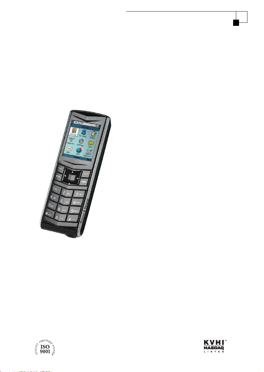
TracPhone IP Handset
User’s Guide
When connected to a KVH® Industries’ TracPhone® FB250 or FB500 terminal,
the IP Handset, manufactured by Thrane & Thrane, allows you to make voice
calls, edit your contacts list, and view system status information. This user’s
guide provides all of the information you need to connect, operate, configure,
and troubleshoot the IP Handset.
Please direct technical questions to:
North/South America, Australia: Europe, Middle East, Asia:
KVH Industries, Inc. KVH Europe A/S
50 Enterprise Center Kokkedal Industripark 2B
Middletown, RI 02842-5279 USA 2980 Kokkedal, Denmark
Tel: +1 401 847-3327 Tel: +45 45 160 180
Fax: +1 401 845-8133 Fax: +45 45 160 181
E-mail: techs@kvh.com E-mail: support@kvh.dk
Internet: www.kvh.com Internet: www.kvh.com
If you have any comments regarding this manual, please e-mail them to
manuals@kvh.com. Your input is greatly appreciated!
KVH Part # 34-126059-F
© 2008-2009, KVH Industries, Inc., All rights reserved.

Trademark Information
TracPhone and KVH are registered trademarks of KVH Industries.
Thrane & Thrane is a registered trademark of Thrane & Thrane A/S in the
European Union and the United States.
Windows and Outlook are registered trademarks of Microsoft Corporation in
the United States and other countries.
Inmarsat is a registered trademark of International Maritime Satellite
Organisation (IMSO) and is licensed by IMSO to Inmarsat Limited and
Inmarsat Ventures plc.
Inmarsat’s product names are trademarks or registered trademarks of
Inmarsat.
All other trademarks are the property of their respective owners.
Disclaimer
Every effort has been made to ensure the correctness and completeness of the
material in this document. No company shall be liable for errors contained
herein. The information in this document is subject to change without notice.
No warranty of any kind is made with regard to this material, including, but
not limited to, the implied warranties of merchantability and fitness for a
particular purpose.

Safety Summary 1
The following general safety precautions must be observed during all
phases of operation, service and repair of this equipment. Failure to comply
with these precautions or with specific warnings elsewhere in this manual
violates safety standards of design, manufacture and intended use of the
equipment. KVH Industries assumes no liability for the customer's failure to
comply with these requirements.
DO NOT OPERATE IN AN EXPLOSIVE ATMOSPHERE
Do not operate the IP Handset in the presence of flammable gases or fumes.
Operation of any electrical equipment in such an environment constitutes a
definite safety hazard.
KEEP AWAY FROM LIVE CIRCUITS
Operating personnel must not remove equipment covers. Component
replacement and internal adjustment must be made by qualified
maintenance personnel. Do not replace components with the cable
connected. Always disconnect power and discharge circuits before touching
them.
DISPOSAL
Old electrical and electronic equipment marked with this
symbol can contain substances hazardous to human beings
and the environment. Never dispose these items together
with unsorted municipal waste (household waste). In order to
protect the environment and ensure the correct recycling of old equipment
as well as the re-utilization of individual components, use either public
collection or private collection by the local distributor of old electrical and
electronic equipment marked with this symbol.
Contact the local distributor for information about what type of return system
to use.
iii

About the Manual 2
Intended Readers
This manual is a user manual for the TracPhone FleetBroadband
IP Handset. The readers of the manual include anyone who is
using or intends to use the IP Handset. No specific skills are
required to operate the IP Handset. However, it is important that
you observe all safety requirements listed in the beginning of this
manual, and operate the handset according to the guidelines in
this manual.
Manual Overview
This manual has the following chapters:
• Introduction contains an overview and a brief description of the
IP Handset.
• Getting started explains how to connect and start up the
handset and gives an overview of the display and keypad. It
also contains a short guide to initial configuration and to
making the first call.
• Operating the IP Handset describes how to use and configure
the handset and explains the display menus.
• Using the web server explains how to use the built-in web
server of the IP Handset.
• Service & maintenance contains guidelines for maintenance of
the handset, a short troubleshooting guide and gives
information on where to get further help if needed.
This manual may not always reflect the latest software
functionality of your IP Handset. To obtain the latest version of the
manual, please visit www.kvh.com and download the latest
version from the FB250 or FB500 product page.
iv

Typography
In this manual, typography is used as indicated below:
Bold is used for the following purposes:
• To emphasize words.
Example: “Do not touch the antenna”.
• To indicate what the user should select in the user interface.
Example: “Select Settings > Display”.
Italic is used to emphasize the paragraph title in cross-
references.
Example: “For further information, see Connecting Cables on
page...”.
COURIER is used to indicate display text.
Example: “The display shows 39558880”.
v

vi

Table of Contents
Safety Summary ................................................................iii
About the Manual ..............................................................iv
Chapter 1 Introduction
Welcome ............................................................................ 1
In this chapter .................................................................... 1
Your IP Handset .................................................................2
Description ..........................................................................2
The wired IP handset ............................................................3
The wireless IP Handset .........................................................4
Features .............................................................................5
Chapter 2 Getting started
In this chapter ....................................................................7
Getting started with the wired IP Handset ..........................7
Introduction .........................................................................7
Connectors ...........................................................................8
Connecting the cables to the IP cradle .....................................9
Installing the cradle ............................................................. 11
Connecting the wired IP Handset to a BGAN terminal ...............12
Starting up the wired IP Handset ...........................................13
Getting started with the wireless IP Handset .....................14
Introduction ........................................................................14
Preparing the hardware ........................................................15
Charging the IP Handset ...................................................... 18
Connecting the IP Handset to your wireless access point ..........20
Establishing a connection using BGAN terminal ............... 22
Using a BGAN terminal ........................................................22
Establishing a connection ....................................................22
Connecting subsequent handsets to the BGAN terminal ...........24
vii

Table of Contents
Making the first call ..........................................................26
The IP Handset keypad and display ..................................27
The keypad ........................................................................27
The display ........................................................................33
Chapter 3 Operating the IP Handset
In this chapter ..................................................................39
User interfaces .................................................................39
IP Handset functions ........................................................ 40
Handling calls ................................................................... 40
Making a call using a BGAN terminal ....................................49
Quick settings .................................................................... 50
How to enter text in the IP Handset .......................................53
Using a headset ..................................................................53
IP Handset menus ............................................................54
Menu overview ...................................................................55
Call log ..............................................................................55
Contacts ............................................................................ 58
Status ............................................................................... 60
Network ............................................................................. 61
Settings .............................................................................67
SIP telephony and profiles ...................................................74
Information from the BGAN terminal .................................... 80
Chapter 4 Using the web server
In this chapter ................................................................. 85
Introduction to the web server ......................................... 85
Browser settings ................................................................ 85
Accessing and navigating the web server ...............................87
viii

Using the web server ........................................................89
The Home page ..................................................................89
Contacts ............................................................................90
Call log ...............................................................................91
SIP settings ........................................................................92
Uploading firmware ............................................................94
Import and Export settings ...................................................95
Help and diagnostics report .................................................97
Chapter 5 Service & maintenance
In this chapter ..................................................................99
Getting support ................................................................99
Maintenance tasks ......................................................... 100
Battery handling for the wireless IP Handset ........................ 100
Cleaning the IP Handset .................................................... 100
Disposal of the IP handset ................................................. 100
Troubleshooting guide .................................................... 101
App. A Technical specifications
Table of Contents
In this appendix ..............................................................103
IP Handset, wired ............................................................103
Specifications, wired handset ..............................................103
Outline dimensions, wired handset ......................................105
IP Handset, wireless ........................................................107
Specifications, wireless handset ..........................................107
Outline dimensions, wireless handset ...................................109
IP cradle outline dimensions ............................................ 111
App. B Conformity
Thrane IP Handset, wired ................................................ 113
CE (LVD & EMC) ................................................................. 113
FCC .................................................................................. 113
ix

Table of Contents
Thrane IP Handset, wireless ............................................ 115
CE .................................................................................... 115
FCC ..................................................................................115
FCC/IC Notice ....................................................................116
Glossary ........................................................................................ 117
Index ........................................................................................ 121
x

Chapter 1
Introduction
Introduction 1
Welcome
Congratulations on the purchase of your IP Handset!
The IP Handset communicates using Voice over Internet Protocol (VoIP), which
means that voice conversations are routed over the Internet or through an IPbased network.
There are two variants of the IP handset: A wired and a wireless variant.
In this chapter
11111
This chapter introduces the IP Handset and gives an overview of its features
and functions.
1

Chapter 1: Introduction
Your IP Handset
Description
The IP Handset is used for
making phone calls over an IP
based network. When used with
a BGAN terminal, the
communication is IP based
between the handset and the
BGAN terminal. From the BGAN
terminal, the call is transmitted
as a normal circuit-switched call.
The IP Handset has some BGAN
terminal control functions. If
configured as handset with the
local number 0501, you can use
the handset to start and stop
data connections (background or
streaming) for all network user
groups.
To improve overall system
overview the IP Handset displays
active, critical alarms from the BGAN terminal to keep you informed about the
status of the BGAN terminal.
The handset is designed specifically for use in harsh environments and it is
dust proof and splash proof.
Excellent sound quality is achieved by including a state-of-the-art echo
canceller and efficient noise suppression software.
On the large 2.2" color TFT screen, a graphical user interface provides easy
access to all functions including contacts and settings. The user interface also
provides direct access to certain features of a connected BGAN terminal.
There are two variants of the handset: A wired model and a wireless model.
2Your IPHandset
Introduction
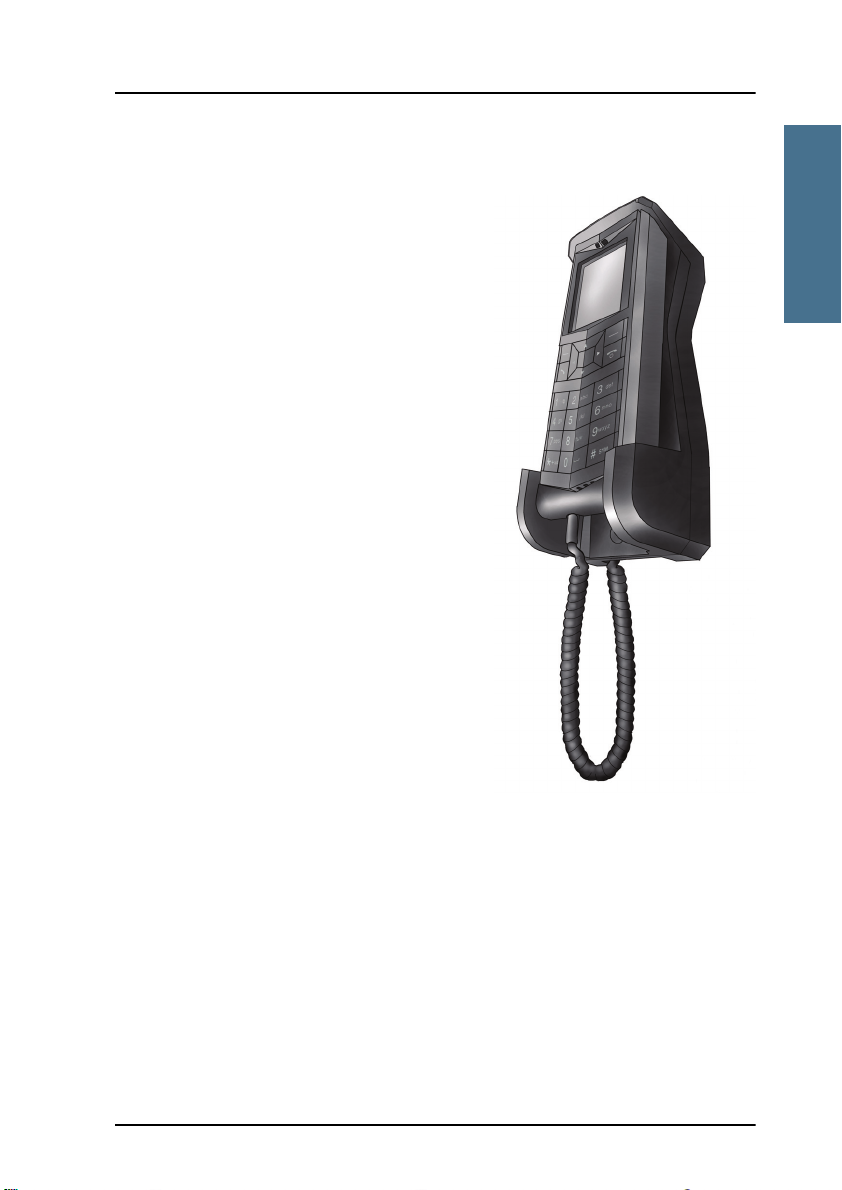
The wired IP handset
The wired handset is powered directly
from the LAN interface using Power over
Ethernet (PoE), so an external power
supply is not needed.
The TracPhone FleetBroadband
IP Handset & Cradle, wired, includes the
following main units:
• TracPhone FleetBroadband
IP Handset, wired
• TracPhone FleetBroadband IP cradle,
wired
The IP Handset connects to the cradle with
a coil cord. The cradle connects with a
fixed LAN cable to a LAN port with PoE, for
example in a BGAN terminal (Broadband
Global Area Network) for satellite
communication.
11111
Chapter 1: Introduction
Your IP Handset 3

Chapter 1: Introduction
The wireless IP Handset
The wireless IP handset connects
to a wireless access point using
Wireless Local Area Networking
(WLAN).
The internal battery is charged
from the dedicated cradle, which
connects to an external power
supply (12-24 V DC).
Due to the improved power
management the wireless
IP Handset can be on stand-by
time for more than 24 hours.
The TracPhone FleetBroadband
IP Handset & Cradle, wireless,
includes the following main
units:
• TracPhone FleetBroadband IP Handset, wireless
• TracPhone FleetBroadband IP cradle, wireless
4Your IPHandset

Chapter 1: Introduction
Introduction
Features
The IP Handset offers the following features:
Voice communication over Internet or IP based network
Start and stop IP data connections in a connected BGAN terminal
Contacts list with up to 100 entries
Intuitive user interface and menu system
Built-in web interface
High quality color display QVGA with night colors
Rugged but elegant design
Splash proof and dust proof
Connectivity to Broadband Global Area Network (BGAN) terminal
BGAN menu to display BGAN terminal type, GPS position and more
11111
Display of critical alarms of the BGAN terminal
Features 5

Chapter 1: Introduction
6Features

Chapter 2
Getting started
Getting started 2
In this chapter
This chapter describes how to install and start up the IP Handset and make the
first call. It also gives an overview of the display and keypad and explains how
to navigate with the keypad.
Getting started with the wired IP Handset
Introduction
22222
The wired IP Handset connects to the cradle with a coil cord. The cradle
connects with a fixed LAN cable to a LAN port with PoE, for example in a BGAN
terminal. The IP Handset is powered directly from the LAN (PoE) interface.
7

Chapter 2: Getting started
Note
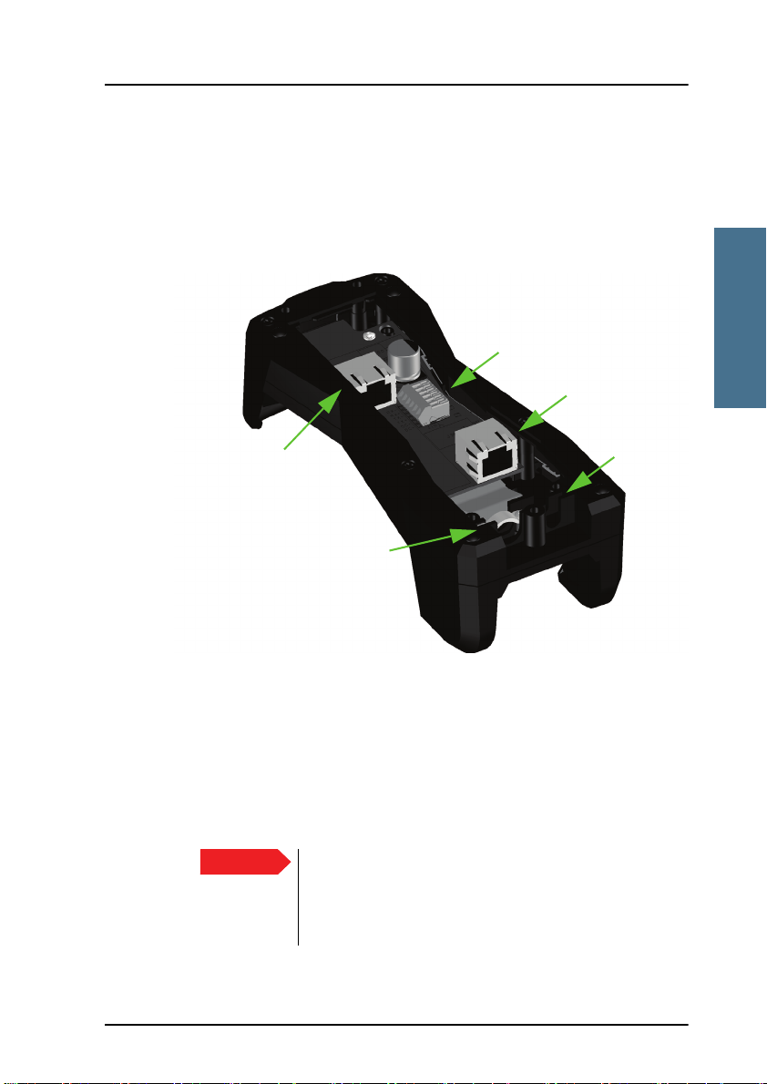
Connectors
IP Handset connectors
The IP Handset has a coil cord with a LAN connector for connecting to the
cradle or directly to a LAN (PoE) interface.
The handset also has two connectors on the side of the handset:
• one connector for connecting a headset.
• one Mini-USB connector.
These two connectors are currently not functional.
IP cradle connectors
The cradle for the IP handset has two internal LAN connectors and an
alternative terminal block for the LAN connection:
• One LAN connector connects to the coil cord from the IP Handset.
• The other LAN connector, or alternatively the terminal block, connects to
your LAN cable between the cradle and the BGAN terminal.
8 Getting started with the wired IP Handset
Chapter 2: Getting started
Getting started
Important
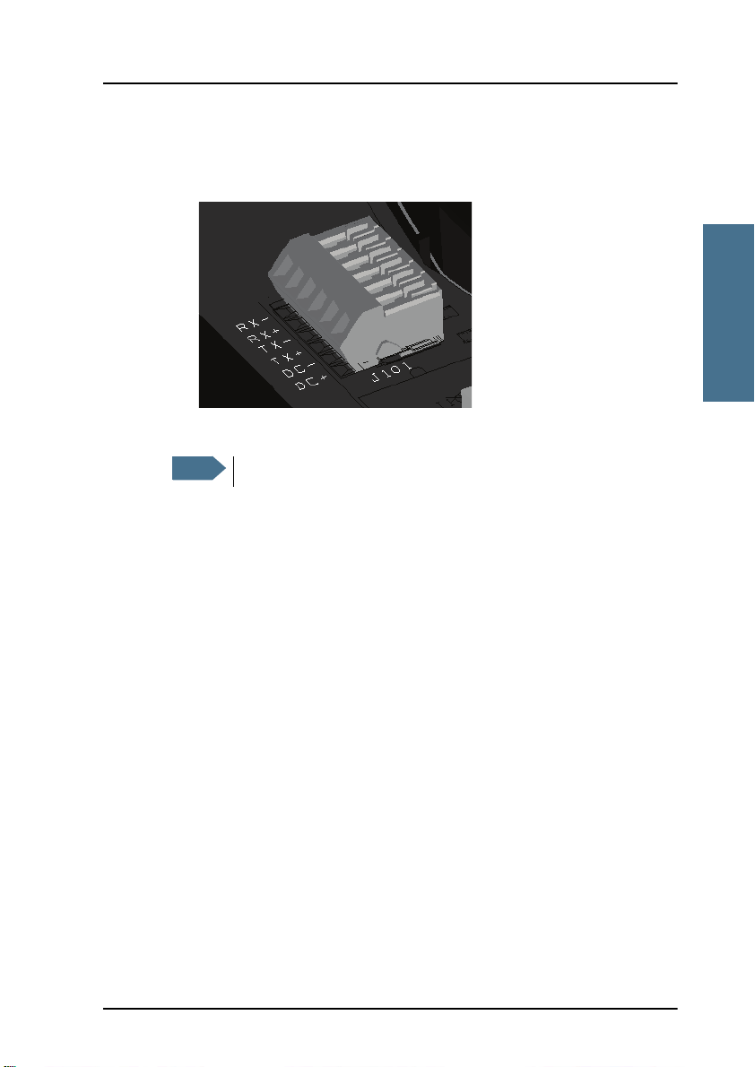
J101
J102
Cable relief
J103
Fit coil cord
here
Connecting the cables to the IP cradle
To connect the cables to the IP cradle, do as follows:
1. Remove the two screws holding the center cover in the bottom of the cradle
and take off the cover.
22222
2. Connect the coil cord from the IP Handset to the cradle connector marked
J103. Then fit the cable relief mounted on the coil cord into the groove at
the cradle exit.
3. To mount the external LAN cable, do one of the following:
• Connect a standard LAN cable to the connector marked J102 in the
cradle. This is the cable for connecting to the BGAN terminal or other
LAN (PoE) interface.
Getting started with the wired IP Handset 9
The space between the cable LAN connector and the
PCB is very scarce - make sure the housing of the cable
connector is not too thick to allow for the connectors to
fit properly.

Chapter 2: Getting started
Note
• Connect the wires of a LAN cable to the terminal block marked J101. The
text next to the terminal block indicates which signal goes where.
4. Mount cable relief at the cable exit from the cradle.
Make sure the cable relief matches the size of the cable.
5. Mount the cover and fasten the two screws.
10 Getting started with the wired IP Handset
Chapter 2: Getting started
Getting started
Installing the cradle
Mount the cradle on a wall or a desktop with 3 screws fitting in the holes
indicated in the drawing below (front view).
22222
Getting started with the wired IP Handset 11

Chapter 2: Getting started
Note
Note
Connecting the wired IP Handset to a BGAN terminal
The LAN interface on the BGAN terminal must supply Power over
Ethernet.
To connect the wired IP Handset to a BGAN terminal do as follows:
1. Start up the BGAN terminal as described in the user manual for the
terminal.
2. Connect the LAN cable from the IP cradle to one of the LAN (PoE)
connectors on the BGAN terminal.
The cable between cradle and terminal must be maximum 80 m.
If you insert a switch or similar between the cradle and the
terminal, make sure that it conforms to the industry PoE standard
IEEE 802.3 af (using data pairs).
The IP Handset starts up automatically when connected to the BGAN terminal.
However, you may have to configure user name and password if the handset
has not been connected before. For further information, see Establishing a
connection using BGAN terminal on page 22.
12 Getting started with the wired IP Handset
Chapter 2: Getting started
Getting started
On/off
key
Starting up the wired IP Handset
To switch on the IP Handset
The wired IP Handset is automatically powered when it is connected to a LAN
interface with PoE.
If the handset has been switched off, you can switch it back on by pressing
and holding the on hook key until the display lights up.
22222
If the handset does not start up, the reason may be that there is no PoE in the
LAN interface. If you are connecting to a BGAN terminal, check that the PoE
indicator on the terminal lights green for the connected port. For further
information, refer to the installation manual for the BGAN terminal.
To switch off the IP Handset, press and hold the on hook key again until the
display is turned off.
Getting started with the wired IP Handset 13
Chapter 2: Getting started
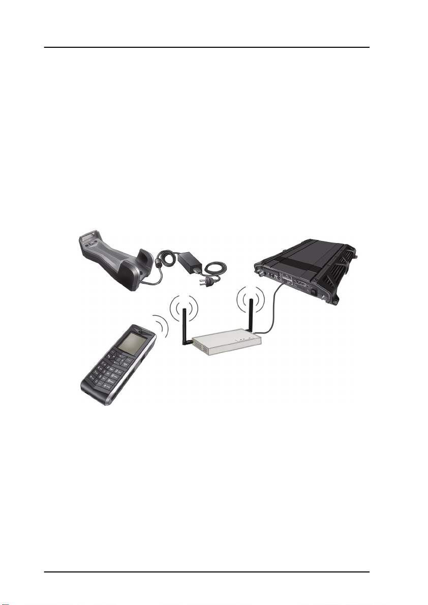
Wireless access point (WLAN)
BGAN terminal
Charging cradle
IP Handset, Wireless
Getting started with the wireless IP Handset
Introduction
Overview
The wireless IP Handset connects to a wireless access point, which is
connected to a BGAN terminal or other IP connection or directly to a BGAN
terminal with integrated wireless access point. The internal battery is charged
from the dedicated cradle connected to an external power supply.
14 Getting started with the wireless IP Handset
Chapter 2: Getting started
Getting started
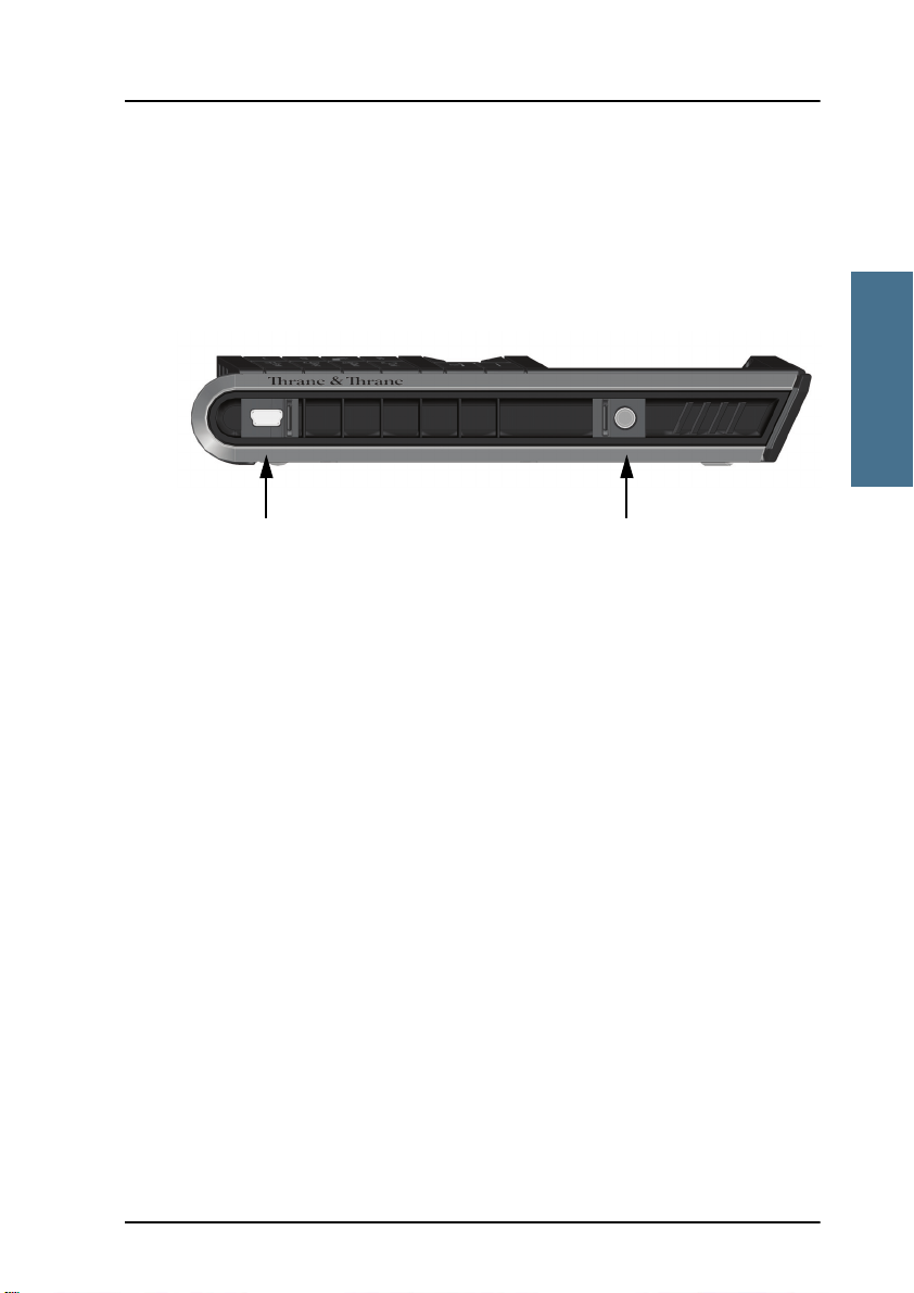
Mini-USB for charging Jack connector for headset
IP Handset connectors
The handset has two connectors on the side of the handset:
• one connector for connecting a headset.
• one Mini-USB 5-pin connector, for charging the handset from a computer
or USB charger.
Preparing the hardware
22222
For the wireless IP Handset you need the following hardware:
• A BGAN terminal with integrated wireless access point or a separate
wireless access point complying to the Wireless Local Area Networking
(WLAN) standard 802.11b/g
• for charging the handset:
• an external power supply with 12 V DC to 24 V DC nominal power,
min. 7 W, or
• a computer and a USB cable with a mini-USB 5-pin connector at one
end and a USB-A connector at the other end.
To connect the wireless access point
If the BGAN terminal has not an integrated wireless access point you may
connect the wireless access point to a BGAN terminal or to your standard
network connection.
For information on how to install the wireless access point, refer to the
documentation that comes with your wireless access point.
Getting started with the wireless IP Handset 15
Chapter 2: Getting started
Terminal block J101
DC Connector
To connect an external power supply to the cradle
The cradle for the IP Handset serves as a charger when it is connected to an
external power supply (12-24 V DC, 7 W).
To connect an external power supply to the cradle, do as follows:
1. On the back of the cradle, unscrew the two screws holding the cover.
2. Remove the cover.
3. Connect your power supply to the cradle.
There are two options for connecting to the cradle:
• Using the internal DC connector in the cradle.
The connector is a proprietary DC Jack, 2.5 mm, positive center.
16 Getting started with the wireless IP Handset
Chapter 2: Getting started
Getting started
Note
• Using the internal terminal block (J101).
Connect the wires from your DC supply to DC+ and DC- in the terminal
block J101.
4. Secure the cable with a cable relief at the cable exit on the cradle.
Make sure the cable relief matches the size of the cable.
5. Mount the cover and fasten the two screws.
22222
For information on how to mount the cradle on a wall or desktop, see
Installing the cradle on page 11.
Getting started with the wireless IP Handset 17

Chapter 2: Getting started
Charging the IP Handset
Introduction
The battery icon next to the handset icon
in the top right corner of the display
shows the battery status of the handset.
When the battery level is critically low,
the handset makes a sound and shows a message, and the icon starts flashing
to indicate that the battery needs recharging. If the battery is not recharged,
the handset will eventually switch off.
There are two options for charging the handset:
• using the cradle with a power supply
• using a USB cable and a computer or USB charger
On delivery the battery of the IP Handset is approximately 50% charged and
ready for use.
To charge the IP Handset using the cradle
The cradle must be connected to an external 12-24 V DC power supply, as
described in the previous section.
Place the IP Handset in the cradle with the display facing up. The handset
automatically starts the charging process.
To charge the IP Handset from a computer or USB charger
You need a computer or a USB charger and a USB cable with a mini-USB 5-pin
connector at one end and a USB-A connector at the other end.
Do as follows:
1. Connect the mini-USB connector to the connector at the side of your
handset.
18 Getting started with the wireless IP Handset
Chapter 2: Getting started
Getting started
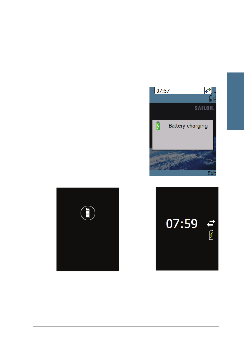
Handset off (animated).
Screensaver mode
The icon is turned off after
a while, but reappears when
a key is pressed.
2. Connect the other connector on the cable to a USB port on your computer
or your USB charger. The IP Handset automatically starts the charging
process.
Indications during charging process
A message appears briefly in the display,
the IP Handset makes a sound and the
battery icon is animated to show that the
battery is charging.
Below are examples of the display when the
IP Handset is off and when it is in
screensaver mode while charging the
battery.
22222
Getting started with the wireless IP Handset 19

Chapter 2: Getting started
Note
Note
Note
If the IP Handset is out of use for a longer period of time, recharge
the battery every two years to avoid deterioration of the battery.
Connecting the IP Handset to your wireless access point
This procedure is only needed at the first connection. Once
connected, the IP Handset automatically attempts to connect to this
access point, whether it is integrated in the BGAN terminal or not,
whenever it is switched on.
To connect the IP Handset to your wireless access point, do as follows:
1. Start up the wireless access point.
2. Switch on your wireless IP Handset by pressing and holding the on hook
key until the display lights up.
3. Press the center select key to enter the menu system.
4. Select Network > Wireless network.
5. When the list of available access points appears in the display, select the
access point you want to connect to.
Access points with a profile matching your IP Handset are
marked with . If this symbol is not present, you cannot
connect to an encrypted network until you have set up your
wireless profile to match the access point. If you select an
encrypted network without a defined profile you are prompted
for security settings.
6. If you are prompted for security settings, select OK to enter the Profiles
menu.
7. In the Profiles menu, select the encryption used in your access point. The
handset supports
•WEP
•WPA2-PSK -AES
20 Getting started with the wireless IP Handset

Chapter 2: Getting started
Getting started
•WPA-PSK-TKIP
8. Select whether your encryption code is hexadecimal or text.
9. Enter your encryption code.
10. Select Connect.
The IP Handset now attempts to connect to your wireless access point. If
the access point is connected to a BGAN terminal, see Establishing a
connection using BGAN terminal on page 22.
When the handset is connected to the access point, the display shows
Connected.
22222
Getting started with the wireless IP Handset 21

Chapter 2: Getting started
Establishing a connection using BGAN terminal
Using a BGAN terminal
Introduction
By connecting the IP Handset to a BGAN terminal you gain access to the BGAN
satellite network with your IP Handset. When the IP Handset is used with the
BGAN terminal, it communicates using Internet protocol between the handset
and the terminal. However, on the BGAN network side of the terminal the call
is transmitted as a circuit switched Standard Voice or 3.1 kHz Audio call.
When connected with the BGAN terminal the IP Handset provides a dedicated
menu for the terminal.
IP Handset connection
The wired handset is connected to the BGAN terminal by connecting the
Ethernet cable from the cradle to one of the LAN ports of the terminal. For
further information, see Connecting the wired IP Handset to a BGAN terminal
on page 12.
The wireless handset is connected to the BGAN terminal either by connecting
to the integrated wireless access point of the terminal or a separate wireless
access point to one of the LAN ports of the terminal. For information on how to
connect the handset to the access point, see Connecting the IP Handset to your
wireless access point on page 20.
Establishing a connection
If one or more handsets have already been connected to the terminal, and the
new handset has not been connected to the terminal before, you must
configure the new IP Handset. You need to set up the user name, password
and local number in the IP Handset and in the web interface of the BGAN
terminal. For further information, see Connecting subsequent handsets to the
BGAN terminal on page 24.
22 Establishing a connection using BGAN terminal

Chapter 2: Getting started
Getting started
Note
If no SIM PIN is required
If the IP Handset is connected to a BGAN terminal where the SIM PIN is
disabled or has already been entered, the BGAN terminal automatically sets
up a communication profile (SIP profile) and assigns the local number 0501 to
the first handset that is connected.
If a SIM PIN is required
If the IP Handset is connected to a BGAN terminal where the SIM PIN is
required and has not yet been entered, you need to enter the SIM PIN for the
terminal. To do so, you need to know the Administrator user name and
password as well as the SIM PIN for the BGAN terminal.
To enter the BGAN terminal’s SIM PIN, do as follows:
1. From the main screen of the handset, press the center select key to enter
the menu system.
22222
2. Select BGAN.
3. Select Enter PIN code.
This menu item is not available if the PIN has already been
accepted. You can check at Status > PIN status to see if the PIN
has been accepted.
4. Enter the Administrator user name and select OK.
For information on how to type text in the handset, see How to enter text in
the IP Handset on page 53.
5. Enter the Administrator password and select OK.
6. Enter the SIM PIN and select OK.
If the SIM PIN is rejected, see the next section Wrong PIN.
When the PIN is accepted, the BGAN terminal automatically sets up a SIP
profile and assigns the local number 0501 to the first handset that is
connected.
Establishing a connection using BGAN terminal 23

Chapter 2: Getting started
Wrong PIN
After entering the user name and password, you have 3 attempts to enter the
PIN, before you are asked to enter the PUK (Pin Unblocking Key). The PUK is
supplied with your BGAN SIM card.
Enter the PUK followed by a new PIN of your own choice. The PIN must be
from 4 to 8 digits long.
Caution! If you enter a wrong PUK 10 times, the SIM card will no
longer be functional, and you have to contact your Airtime
Provider for a new SIM card.
IP Handset ready
When the display shows the handset ready symbol in the upper right
corner, the handset is ready for making a call.
If the handset ready symbol is crossed out you cannot make a call. The
display will normally show a message explaining why the handset is not
ready.
Connecting subsequent handsets to the BGAN terminal
If one ore more handsets have already been connected to the terminal, you
need before, you must configure the new IP Handset. You need to set up the
user name, password and local number in the IP Handset and in the web
interface of the BGAN terminal.
To set up the IP Handset
To enter the user name and password in the IP Handset, do as follows:
1. Start up the IP Handset as described in the previous sections.
2. Enter the menu system and select SIP.
3. Move to the BGAN profile and select Options (left select key).)
24 Establishing a connection using BGAN terminal

Chapter 2: Getting started
Getting started
4. Select Edit/View.
5. Select User name and enter the user name for your handset. Note that the
user name must be the same as the local number for your handset when
using the BGAN terminal. Available numbers are 0501 to 0516.
6. Select Password and enter the password for your handset. Note this
password for later use in the terminal.
7. Exit the IP Handset menu.
To set up the BGAN terminal
To match the IP Handset with the BGAN terminal you must enter the local
number and password in the web interface of the BGAN terminal.
To set up the BGAN terminal, do as follows:
1. Connect a computer to the LAN interface of the BGAN terminal and start up
your browser.
22222
2. Enter the IP address for the terminal. The default IP address is 192.168.0.1.
The web interface opens.
3. Select SETTINGS > IP handsets.
4. Locate the local number that matches the user name (local number) of your
handset and click New.
5. Enter the same password you entered in the handset.
When the terminal and the handset have recognized each other, a
Configure link appears next to the new handset in the web interface of the
terminal. Click the Configure link to open the internal web interface of the
IP Handset. For information on the IP Handset web interface, see Using the
web server on page 85.
Establishing a connection using BGAN terminal 25

Chapter 2: Getting started
Making the first call
To make a call, do as follows:
1. Type the phone number on the keypad.
If the number is in the Contacts list of the
handset, you can also select the number
from there and dial up with the off hook
key.
2. Press the off hook key in the left side of
the keypad or press #.
The display shows that the number is
being dialled.
For further information on how to make calls,
see Handling calls on page 40.
26 Making the first call

Chapter 2: Getting started
Getting started
Left select
Off hook
Right select
On hook/ Power
Select
Up/ Down/ Left/ Right
Alpha-numeric
keys
The IP Handset keypad and display
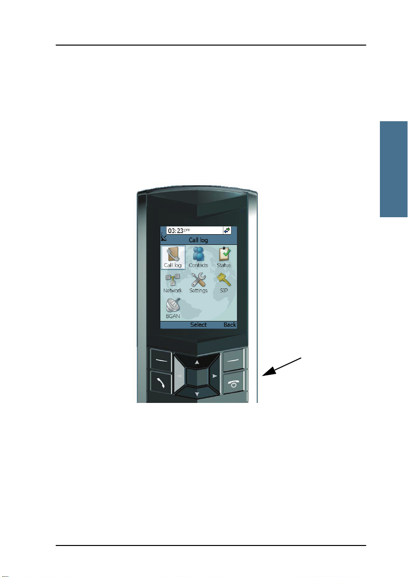
The keypad
The following drawing shows the keypad of the handset.
22222
The next sections explain the functions of each key in the keypad.
The IP Handset keypad and display 27

Chapter 2: Getting started
Control keys
The below table shows the functions of the control keys in the upper section of
the keypad.
Key Functions
Left select.
Selects the function shown in the display just above the key
(left soft key).
Right select.
Selects the function shown in the display just above the key
(right soft key).
From main screen: Opens the Contacts list.
Off hook.
After entering a phone number: Initiates a call to the number.
From main screen: Opens a list of the latest calls, including
incoming, outgoing and missed calls.
On hook/ Power.
When the handset is ringing: Rejects the call.
During a call: Ends the call.
When in the menu system: Abandons the menu system and
displays the main screen.
Otherwise: Powers the handset on/off, when pressed and held
for 3 seconds.
If there is an error and the handset does not power off after
approximately 3 seconds, hold the key for 10 seconds, and the
handset will perform a hardware reset.
28 The IP Handset keypad and display

Getting started
Key Functions
Select (center).
Selects/confirms the function highlighted in the display.
22222
Chapter 2: Getting started
Navigation.
Navigates through the menu system in the display.
Right/Left are also used to change settings in the menus.
See also Keypad shortcuts on page 32.
The IP Handset keypad and display 29

Chapter 2: Getting started
Alpha-numeric keys
This section shows the functions of the
alpha-numeric keys in the lower
section of the keypad.
The functions available depend on
whether you are typing a phone
number (number mode) or text (text
mode).
In number mode, you get the number
of the key pressed. Only has two
functions.
Press once: The display shows .
Press twice, or press and hold: The display shows +.
Press #: The display shows #.
See the available functions in text mode on the next page.
In text mode, you have the functions listed below.
The key switches between text and number mode. There are three options:
Numeric, lowercase and uppercase characters. You can see in the lower left
corner of the display which mode is currently selected.
To get numbers from lowercase or uppercase mode, press and hold the key.
At numerous presses on the same key, the character changes in the same
sequence that the characters are listed in the following table.
Key Numeric output Lowercase output Uppercase output
1 1 . , @ : - ? . , @ : - ?
2 2 a b c A B C
3 3 d e f D E F
30 The IP Handset keypad and display

Chapter 2: Getting started
Getting started
Key Numeric output Lowercase output Uppercase output
4 4 g h i G H I
5 5 j k l J K L
6 6 m n o M N O
7 7 p q r s P Q R S
8 8 t u v T U V
9 9 w x y z W X Y Z
0 0 [space] [space]
22222
Switches between lowercase, uppercase and numbers
# Symbols. Displays a list with the following additional symbols:
. / : @ $ % ^ & * ( ) ~ ‘ - _ = + [ ] { } \
| ; ´ “ ! < > , ? # € <CR>
The IP Handset keypad and display 31

Chapter 2: Getting started
To navigate with the keypad
To enter the menu system from the main screen, press the center select key.
To move through the menus, press the navigation keys (arrows).
To select a highlighted menu item, press the center select key.
To select one of the items in the action texts area, press the key just below the
text you want to select.
To go back one level in the current menu, press the right select key (only when
Back is displayed above the key).
Keypad shortcuts
The following shortcuts are available:
When the display is in the main screen, this key gives
direct access to the list of contacts.
When the display is in the main screen, this key opens a
list of the latest incoming, outgoing and missed calls.
When the display is in the menu system, the on hook key
will exit the menu system and show the main screen.
When the display is in the main screen, the right select
key will open the list of contacts.
From inside the Contacts list, press the first letter of an
entry to access the entry in the Contacts list.
Alpha-numeric
keys
32 The IP Handset keypad and display
When the display is in the menu system, an alphanumeric key will jump to the menu item with the pressed
number or, in the Contacts list, to the first entry
beginning with the pressed letter.

Chapter 2: Getting started
Getting started
Time IP Handset
call status
Selected menu item
General Signal (and battery)
Action texts area
Main display area
Signal and battery
status for wireless
IP Handset
status for BGAN terminal indications
The display
The color display of the IP Handset is divided into sections with different types
of information. The sections are outlined below.
22222
BGAN signal and battery status
When the IP Handset is connected to a BGAN terminal, the display shows the
signal strength of the BGAN signal. If the BGAN terminal is battery powered,
the battery status is also displayed.
The IP Handset keypad and display 33

Chapter 2: Getting started
Time
The display shows the time of day.
The format is selectable in the Settings > Date and time menu.
General indications
General indications are icons that show dynamic information such as missed
calls, sounds off, keypad locked and microphone muted.
For explanations of the icons, see Icons in the display on page 35.
IP Handset call status
This field shows handset status such as whether or not the handset is ready for
making calls, or whether there is an ongoing call.
For explanations of the icons, see Icons in the display on page 35.
Signal and battery status for wireless IP Handset
This field shows the signal strength for the wireless connection and battery
status for the wireless handset.
Main display area
The main display area primarily displays the menus and messages to the user.
Action texts area
The action texts are used to indicate an action that takes place when the
corresponding key is pressed. The corresponding key is the key directly below
the text (left select, center select or right select).
34 The IP Handset keypad and display

Getting started
Icons in the display
The below table explains the icons in your display.
Icon Meaning
Wireless handset (used together with signal strength
and battery status).
BGAN terminal connected (used together with signal
strength and battery status if relevant).
Signal strength for wireless handset and/or for BGAN
terminal.
Battery status for wireless handset and/or for BGAN
terminal.
22222
Chapter 2: Getting started
The handset is ready for making calls.
The handset is not ready for making calls.
Active critical alarm in BGAN terminal.
Incoming call - not yet answered (the handset is
ringing).
Incoming call in progress.
The IP Handset keypad and display 35

Chapter 2: Getting started
Icon Meaning
Outgoing call - not yet answered.
Outgoing call in progress.
Call ended.
Missed call.
See the Call log for information on the call.
The microphone is muted.
To reactivate the microphone, select
Options (left select key) > Microphone.
The handset is in silent mode. All external sounds from
the handset - including ring tones - are muted. Voice is
not muted.
This symbol is shown when you are adjusting the
volume.
The keypad is locked.
To unlock the keypad, press the center select key
followed by the left select key.
This symbol is used in the Contacts list to indicate that
the number is from the phone book of the BGAN
terminal and is read-only.
36 The IP Handset keypad and display

Getting started
Icon Meaning
When an alpha-numeric key is pressed from inside the
Contacts list, this symbol is shown while the handset is
searching for entries with the letter pressed.
Wait - a task is in progress.
Shown in the list of wireless access points: The wireless
connection is encrypted.
Shown in the list of wireless access points: The wireless
connection is not encrypted.
Shown in the list of wireless access points: The profile
for the wireless access point matches the handset.
22222
Chapter 2: Getting started
Screensaver
You can choose to have a screensaver
activated when the handset is not used for
one minute. This screen shows only the time,
handset status and general indications such
as missed calls.
When you press a key the display returns to
the normal display function.
To enable or disable the screensaver, enter
the menu system, select Settings > Display
and select Screensaver. When the box is
checked, the screensaver is enabled.
The IP Handset keypad and display 37

Chapter 2: Getting started
38 The IP Handset keypad and display

Chapter 3
Operating the IP Handset
Operating the IP Handset 3
In this chapter
This chapter describes how to use the IP Handset. It also describes how to
configure the IP Handset and use the display menu system, including a short
description of how to use the IP Handset with a BGAN terminal.
For information on how to connect and start up the handset, and how to
navigate with the keypad, refer to the previous chapter, Getting started.
User interfaces
The main user interface for the handset is the display menu system. However,
with a computer and a browser you can also use the built-in web server to
access a subset of the handset settings. This way you can take advantage of a
larger screen and still access a subset of the handset settings.
33333
• The display menu system is described in IP Handset menus on page 54.
For an overview of the keys and display, and explanation of keys and
display symbols, see The IP Handset keypad and display on page 27.
• The web server is described in Using the web server on page 85.
39

Chapter 3: Operating the IP Handset
Note
IP Handset functions
Handling calls
Handset ready
When the status field for the
IP Handset shows ready ,
you can make or receive calls.
To make a call
To make a call, simply type the phone number and press or #.
If the handset is in the cradle while you make the call, the mode will
automatically be hands-free (default function). For further
information, see To set up the function of the cradle on page 70.
40 IP Handset functions

Chapter 3: Operating the IP Handset
Operating the IP Handset
Press off hook
Hang up
The call is answered
The display shows the progress as follows:
33333
You can also call a number from your contacts or from a list of recent calls:
• Contacts: Press the right select key from the main screen and move to the
contact you want to call. Then press the off hook key.
• Recent calls: To see the latest calls (incoming, outgoing and missed calls),
press from the main screen. Press again to call the selected
number.
IP Handset functions 41

Chapter 3: Operating the IP Handset
Note
Exter nal caller Taking external
call
Final
Destination
1: Call 2: Transfer call
For information on how to make calls using a BGAN terminal, see Making a
call using a BGAN terminal on page 49.
To receive a call
When the handset is ringing, the display
shows the calling name or number, if
known.
Answer the call by pressing the off hook key
in the left side of the keypad , or by
removing the handset from the cradle. For
information on cradle detection, see To set
up the function of the cradle on page 70.
If the handset is in the cradle while
you answer the call, the mode will
automatically be hands-free (by
default).
Any open menus are closed down when the handset is ringing.
You can see unanswered calls under Call log in the IP Handset menus or in
the web interface.
To transfer a call
When you receive a call, you can transfer it to another phone connected to the
terminal. The most commonly used scenario is that you make a blind transfer.
This means that you transfer the call directly to a new number, without talking
to the new number before putting the call through.
42 IP Handset functions

Chapter 3: Operating the IP Handset
Operating the IP Handset
To transfer a call, do as follows:
1. Having taken the call, you press Options.
2. Scroll to Transfer <number to transfer>
and press Select.
33333
3. If the local numbers are entered in the
phone book, the display shows the local
numbers available for transferring the
call.
In the example you can transfer the call to
one of the local phones Local 0301 or
Local 0503.
IP Handset functions 43

Chapter 3: Operating the IP Handset
4. If there are no entries for local phones in
the phone book, select Enter number and
press Select.
In the example the call is transferred to the
local phone 0503.
5. Enter the local number, in this case 0503,
and press Trans fe r. The BGAN terminal
makes sure that the call is transferred
properly to the new local number.
The phone with the local number you
dialed starts to ring.
6. The incoming call is handed over to 0503.
When the call is taken, it is established
between the initial caller and the new
recipient
44 IP Handset functions

Chapter 3: Operating the IP Handset
Operating the IP Handset
External caller Taking external
call
Final
Dest ination
1: Call
3: Announce call
2: Hold
4: Terminat e announce call
5: Tran sfer call
To transfer a call with announcement
When transferring a call, you can put the current call on hold, call the new
number and announce the call to be transferred, terminate the announcement
call and then transfer the original call.
To transfer a call with announcement, do as
follows:
33333
1. Having taken the call, you press Options.
IP Handset functions 45

Chapter 3: Operating the IP Handset
2. Select Hold and press Select.
3. The incoming call is put on hold.
4. Select Enter number to enter the local
number you want to transfer the call to or
select Contact search to select a number
from the Contacts list.
5. In this example the original call is
transferred to the local phone 0503. The
phone with the local number you dialed
starts to ring.
46 IP Handset functions

Chapter 3: Operating the IP Handset
Operating the IP Handset
Note
6. When 0503 picks up the call you can
announce the original call that is on
hold.
7. To be able to transfer the original call
that is on hold, the announcement call to
the local number must be terminated,
either by you or the final recipient. This is
to free the line for the original call.
Press the on-hook key to terminate
the announcement call, in this example
the call to 0503.
In case you need to talk to the original
caller again, press Switch.
33333
8. If you wish to talk to the original caller
again before transferring the call, select
Unhold.
Select Transfer to transfer the original caller.
Proceed as described in To transfer a call on
page 42.
The BGAN system only supports
one external call at a time.
IP Handset functions 47

Chapter 3: Operating the IP Handset
To end or reject a call
Press the on hook key to end an ongoing call or to reject an incoming
call.
When the handset is in hand-held mode, you can also end the call by placing
the handset in the cradle.
48 IP Handset functions

Chapter 3: Operating the IP Handset
Operating the IP Handset
Note
Note
Making a call using a BGAN terminal
When making a call with the IP Handset using a BGAN terminal you use the
BGAN network and its functionality.
To make a call from a handset connected to a BGAN terminal
To make a call from a phone or handset connected to a BGAN terminal, dial
00 <country code> <phone number> followed by or #.
Example: To call the number +45 39558800,
dial 00 45 39558800 followed by or #.
The default call type is set up in the web interface of the BGAN
terminal. However, you can select the call type for your call, using a
prefix.
Dial 1 before the number to make a Standard Voice call.
33333
Dial 2 before the number to make a 3.1 kHz Audio call.
Example: Dial 2 004539558800 to make a 3.1 kHz Audio call to the
number +45 39558800.
To make a call to a handset connected to a BGAN terminal
By default all handsets connected to the terminal will ring on
incoming calls.
To make a call to a handset connected to the terminal, dial
+870 <Mobile number>
• + is the prefix used in front of the country code for international calls. This
is 00 when calling from most countries.
• Mobile number: The mobile number of the terminal you are calling.
Example: If you are calling from Denmark and the mobile number for 3.1 kHz
Audio is 772112345 on your terminal, and you want to make a call
to the terminal using 3.1 kHz Audio, dial 00 870 772112345.
IP Handset functions 49

Chapter 3: Operating the IP Handset
Note
To see the mobile numbers of your terminal, refer to the information included
with your airtime subscription.
There are two Voice numbers, one for Standard Voice and one for
3.1 kHz Audio.
For more information on call types and the BGAN terminal, refer to the user
manual for your BGAN terminal.
Quick settings
To control the volume
To adjust the voice volume during a call (with the display in the main screen),
press or on the keypad.
To use hands-free operation
To enable hands-free operation during a call, use the right select key to select
Handsfree. To go back to hand-held mode, press the right select key again.
In hands-free mode the sound is routed to a speaker, so that you can use the
phone without holding it close to the ear. You can adjust the volume with
or as described in the previous section.
Handset in cradle:
You can also make a hands-free call by leaving the handset in the cradle while
making the call. Similarly you can answer a call using hands-free mode by
leaving the handset in the cradle while answering the call.
In both cases, the default function is as follows:
• If you remove the handset from the cradle during the call, the mode will
automatically change to hand-held.
• When the handset is out of the cradle in hand-held mode, the call will be
terminated when you put the handset back in the cradle.
50 IP Handset functions

Chapter 3: Operating the IP Handset
Operating the IP Handset
Note
• When the handset is out of the cradle in hands-free mode, you can put it
back in the cradle without terminating the call.
You can change this default function under Settings > Cradle, if you
want the handset to be independent of the cradle. For further
information, see To set up the function of the cradle on page 70.
To mute the microphone
You can mute the microphone of the IP Handset. To mute the microphone
during a call, do as follows:
1. Select the left Options menu.
2. Select Microphone mute.
To lock the keypad
33333
You can lock the keypad of the IP Handset. When the keypad is locked you can
still answer incoming calls. To lock the keypad, do as follows:
1. Select the left Options menu.
2. Select Lock keypad.
To unlock the keypad, do as follows:
1. Press the center select key.
2. Press the left select key.
IP Handset functions 51

Chapter 3: Operating the IP Handset
Note
To use night mode
The display has a night mode for operation in
low light areas. In night mode, the colors are
changed to make the display more suitable
for night operation. The IP Handset can be
set to automatically switch between day and
night mode.
If the automatic switch between day and
night mode is not selected, you can activate
the night mode manually.
To activate night mode, do as follows:
1. Select the left Options menu.
2. Select Night mode.
To set the IP Handset to automatic switch between day and night mode see To
set up the display on page 71.
To use stealth mode
Stealth mode is used when the IP Handset should not be noticed. In stealth
mode you can turn off all lights in the display and/or sounds for external
events. Note, however, that the keypad will still light up when you press a key.
To activate stealth mode, do as follows:
1. Select the left Options menu.
2. Select Stealth mode.
Stealth mode is only activated for the items you have selected in the
menu Settings, Stealth. See To set up stealth mode on page 68.
52 IP Handset functions

Chapter 3: Operating the IP Handset
Operating the IP Handset
How to enter text in the IP Handset
When entering your contacts in the IP Handset you use the keypad to enter the
names.
Press before the alpha-numeric key to switch between lower case, upper
case and numbers.
There are 3 or 4 letters on each key. To obtain the next letter on the key, press
the key again.
To move the cursor in the text, use the arrow keys.
To delete the letter just before the cursor, press the left select key Clear. Hold
the key to delete all the text.
For a list of the key-functions in text-mode, see the table on page 30.
Example
33333
To type “He”, do as follows:
1. Press one or two times until the lower left corner of the display shows
upper case letters.
2. Press the key 4 ghi two times to display the letter H.
3. Press again until the lower left corner of the display shows lower case
letters.
4. Press the key 3 def two times to display the letter e.
Using a headset
You can connect a headset to the wireless IP Handset as follows:
Plug the headset jack into the jack connector on the side of the handset.
The microphone and speaker of the IP Handset are automatically disabled and
the headset is used instead.
IP Handset functions 53

Chapter 3: Operating the IP Handset
IP Handset menus
The menu system gives you access to the user parameters of the IP Handset.
To access the menu system from the main screen, press the center select key.
Move around in the menus with the arrow keys and select with the select keys.
Leave the menu system by pressing the on hook key.
54 IP Handset menus

Chapter 3: Operating the IP Handset
Operating the IP Handset
Note
BGAN
Regi stered
Profile 2
Not in use
Profile 3
Not in use
Miss ed calls
Received calls
Dialled numbers
Manage
Main menu
Phone identific ation
Network information
Softw are vers ion
Sound
Stealth
Call services
Cradle
Display
Web serv er
Date and t ime
Language
Fact ory default
Wireless network
Settings
Noise c ancellation
Echo canc ellation
Use BGAN tim e
Time
Date
Format (12/24h)
Time z one
Active backlight (%)
Standby bac klight (%)
Screensav er
Transparenc y
Automat ic day/night
Ringing tone
Tones v olume
Keypad clic k
Suppress audio
Suppress bac klight
Use s tealth
Country
Automatic IP (DHCP)
GPS position
Status
CNo (s ignal strengt h)
PIN s tat us
Access P 1
Connected
Access P 2
Answer w hen lift ed
Terminal t ype
Terminal SW version
User Group
Group nam e
Profile A
Activ e
Profile B
Inactive
Main Options
Call log
Contacts
Status
Network
Settings
SIP
BGAN
Connect (0501 only)
Status
Properties
Enter PIN code *
Activ e alarms **
Hold/Switch *
Transf er *
Handsf ree *
Microphone m ute *
Lock keypad
Stealth m ode
Night c olours
* for active calls
* if needed
** if any
Menu overview
The following drawing shows an overview of the menu system.
Wired IP Handset only: The menus Wireless network under Network
and Country under Network > Settings are not present.
33333
Call log
The IP Handset logs all calls and dialled numbers. The log entry shows the
name (if known), the number, time of the call and duration. Note that the call
log can hold maximum 100 calls. You can delete calls from the call log.
IP Handset menus 55

Chapter 3: Operating the IP Handset
To display the call log
To display the call log do as follows:
1. From the main menu, select Call log.
2. Select the list you want to see.
3. If you want to see details for a call, move
to the call and select View.
To add a number from the call log to the Contacts
To add a number from the call log to the Contacts do as follows:
1. In the call log, go to the call and select Options.
2. Select Add to contacts.
Note that the Contacts list can hold maximum 100 entries.
3. Type in the name of your new contact and select OK.
56 IP Handset menus

Operating the IP Handset
To delete a number from the call log
To delete a number from the call log do as follows:
1. In the call log, go to the call and select Options.
2. Select Delete.
3. Select Ye s.
To delete all numbers in a call log folder
To delete all numbers in the call log, or all
numbers in a sub-folder of the call log, do as
follows:
1. In the call log menu (not in one of the
sub-folders) select Manage.
33333
Chapter 3: Operating the IP Handset
2. Select the folder you want to empty.
3. Select Ye s.
To see memory usage in the call log
To see the number of stored entries and the maximum allowed number of
entries, do as follows:
1. In the call log menu (not in one of the subfolders) select Manage.
2. Select Memory usage.
IP Handset menus 57

Chapter 3: Operating the IP Handset
Contacts
Use the contact list of the IP Handset to find a contact and make a call or
manage your contacts. You have access to the contacts in the BGAN phone
book.
To display your contacts
To display your contacts, do one of the following:
• From the main screen, press the right select key,
• from the main screen, press , or
• from the main menu, select Contacts.
If a contact is from the BGAN phone book it is marked with . This means
you cannot edit or delete the entry.
To call a contact
To call a contact, do as follows:
1. In your Contacts list, scroll to the contact you want to call.
2. Press the off hook key.
To add a contact
To add a contact, do as follows:
1. In your Contacts list, press the left select key, Options.
2. Select Add.
Note that the Contacts list can hold maximum 100 entries.
3. Type in the name of your contact and select OK.
The name can be maximum 32 characters.
For information on how to enter text, see How to enter text in the
IP Handset on page 53.
58 IP Handset menus

Chapter 3: Operating the IP Handset
Operating the IP Handset
4. Scroll to Number and select Edit.
5. Type in the number of your contact and select OK.
The number can be maximum 32 characters.
To edit a contact
To edit a contact, do as follows:
1. In your Contacts list, scroll to the contact you want to edit.
2. Press the left select key, Options.
3. Select View/Edit.
4. Select Edit.
5. Change the name of your contact and select OK.
For information on how to enter text, see How to enter text in the
IP Handset on page 53.
33333
6. Scroll to Number and select Edit.
7. Change the number of your contact and select OK.
To delete a contact
To delete a contact, do as follows:
1. In your Contacts list, scroll to the contact you want to delete.
2. Press the left select key, Options.
3. Select Delete.
4. Press the left select key, Ye s.
The contact is now deleted from your Contacts list.
IP Handset menus 59

Chapter 3: Operating the IP Handset
Status
In the Status section you find the serial number of the IP Handset and the
network settings. Use this menu to display the software version of the
IP Handset.
To view status for the handset, do as follows:
1. From the main menu, select Status.
2. Select Phone identification to see the
serial number of the IP Handset.
3. Select Network information to see:
• DHCP Enabled/Disabled
• IP address
• Subnet mask address
• Default gateway
• Physical address (MAC)
4. Select Software version to see the version of the IP Handset software.
60 IP Handset menus

Chapter 3: Operating the IP Handset
Operating the IP Handset
Note
Network
The Wireless network menu described in the following sections is
only available in the wireless handset. For the wired handset, go to
To select the IP mode on page 66.
To connect the IP Handset to the wireless network
If your handset has been connected to the wireless access point before, it will
automatically attempt to establish a connection as soon as the access point is
within reach.
If it is the first time you connect the IP Handset to the wireless access point,
you need to manually connect to the access point.
To connect the IP Handset to the access point,
do as follows:
33333
1. Start up your wireless access point.
2. Start up the IP Handset.
3. Enter the menu system and select
Network > Wireless network.
A list appears with all wireless access
points within reach, together with
previously connected access points.
• : the handset already has a profile
for this access point.
• : the access point uses encryption.
• : the access point does not use encryption.
The connected access point (if any) is always placed at the top.
IP Handset menus 61

Chapter 3: Operating the IP Handset
4. Select Connect at the network you want
to connect to.
If your access point does not use
encryption, the handset will
automatically connect and create a new
profile for the access point.
5. If your access point uses encryption and
it is the first time you connect, you will
be prompted for security settings.
6. Select OK to enter the Profiles menu.
Then enter the encryption key as
described in the next section (from step
5).
When the profile matches the access point, and you have selected Connect,
the IP Handset attempts to establish a connection. If the access point is
connected to a BGAN terminal, see Using a BGAN terminal on page 22 for
information on how to connect to the BGAN network.
When the IP Handset is ready for use, you see the handset ready symbol
in the top right corner of the display.
Normally a new profile is automatically created when you connect to an access
point.
62 IP Handset menus

Operating the IP Handset
To edit a Wireless network profile
To edit a Wireless network profile, do as
follows:
1. From the main menu, select Network >
Wireless network.
2. Select the access point you want to
change profile for.
3. Press the left select key, Options.
Note that if no profile is defined for the
selected access point, this menu will only
show Connect and Manage.
4. Select Edit/View profile.
There are four types of profile, depending on the type of encryption used.
The four types of encryption are:
•WEP
•WPA-PSK-TKIP
•WPA2-PSK-AES
•No security
The SSID (name of the Wireless network) and security mode of the selected
access point are automatically detected by the handset.
33333
Chapter 3: Operating the IP Handset
5. If you are using encryption of the type WPA or WPA2, select whether you
want to enter the encryption key in hexadecimal numbers or text.
6. Enter your encryption key.
7. Select one of the following:
• Connect (left key) if you want to connect immediately to the access
point, or
• Back (right key) if you want to save the profile for later.
IP Handset menus 63

Chapter 3: Operating the IP Handset
Important
To delete a Wireless network profile
To delete a Wireless network profile, do as
follows:
1. In the Wireless network list, go to the
access point for which you want to delete
the profile.
2. Select Options (left select).
3. Select Delete profile.
4. Select Ye s (left select).
The profile for the selected access point is
now deleted. If the access point uses
encryption, your handset will not be able to
connect to the access point unless the security settings are entered again.
To delete all Wireless network profiles
To delete all Wireless network profiles, do as
follows:
1. From the Wireless network list, select
Options (left select).
2. Select Manage.
3. Select Delete all profiles.
When you delete all
profiles you will not be able
to connect to any access
point using encryption,
unless you enter the
security settings again!
4. Select Ye s (left select) to confirm.
64 IP Handset menus

Chapter 3: Operating the IP Handset
Operating the IP Handset
To create a new Wireless network profile
Normally a new profile is automatically created when you connect to an access
point. If needed, you can define a profile for an access point that is not
currently within reach.
To create a new Wireless network profile, do
as follows:
1. From the Wireless network list, select
Options (left select).
2. Select Manage.
3. Select Add profile.
4. Type in the SSID of the access point.
5. Select OK.
A new profile is now created
33333
6. Enter the security information for the
access point. For further information, see To edit a Wireless network profile
on page 63.
To see memory usage in the list of Wireless network profiles
To see the number of stored profiles and the
maximum allowed number of profiles, do as
follows:
1. From the Wireless network list, select
Options (left select).
2. Select Manage.
3. Select Memory usage.
IP Handset menus 65

Chapter 3: Operating the IP Handset
Important
To set the country for Wireless network use
To make sure you have the right settings for the country your IP Handset is
currently located in, you have to enter the country in the handset.
In some countries, the use of Wireless networks (WLAN) is not
allowed. Before continuing, make sure WLAN is allowed and
licensed in the country where you intend to use it.
To enter the country, do as follows:
1. Select Network > Settings > Country.
2. Scroll to the country your handset is located in and select it.
If the country is not in the list, select Other.
To select the IP mode
You can select whether or not the IP Handset should use DHCP to
automatically obtain an IP address. Static IP addresses are also supported. It is
recommended to use DHCP. Automatic IP (DHCP) is the default setting.
To select the IP mode, do as follows:
1. From the main menu, select Network.
2. Select Settings.
3. Do one of the following:
• If the IP Handset should use DHCP to
automatically obtain an IP address,
check the box next to Automatic IP
(DHCP) and select Back or press the
on hook key to exit completely.
• For a static IP address, clear the box
next to Automatic IP (DHCP). Then
select Yes to confirm and continue to
the next step.
66 IP Handset menus

Operating the IP Handset
4. If you selected not to use DHCP, scroll
down to IP address.
5. Click Edit, type in the IP address and
select OK.
6. Continue to Subnet mask, Gateway,
Primary DNS and Secondary DNS and
enter them in the same way.
7. S e le c t Back or press on hook to exit.
The handset will now use the static
information you entered, instead of
automatic IP address allocation using
DHCP.
Settings
To access the Settings menu, select Settings
from the main menu.
33333
Chapter 3: Operating the IP Handset
IP Handset menus 67

Chapter 3: Operating the IP Handset
Note
To adjust the sound
You can adjust the ringing tone, the tone volume and the keypad click.
To adjust the sounds of the handset, do as
follows:
1. From the Settings menu, select Sound.
2. Use the arrow keys to move to the sound
you want to adjust.
3. For Keypad click, select Edit to change
the setting.
4. For the other settings, use the keys
and to change the setting, or
select Edit, select the setting you want
and select OK.
To set up stealth mode
Stealth mode is used when the IP Handset should not be noticed. In stealth
mode you can turn off all lights in the display and/or sounds for external
events. Note, however, that the keypad will still light up when you press a key.
To configure and go into stealth mode, do
as follows:
1. From the Settings menu, select Stealth.
2. Move to Suppress audio and/or
Suppress backlight and select Edit to
change the setting.
These settings are only activated
when Use stealth is checked.
3. Move to Use stealth and press Edit to
check/clear the box.
68 IP Handset menus

Chapter 3: Operating the IP Handset
Operating the IP Handset
4. When stealth is set up and Use Stealth is selected in this menu, you can
activate and deactivate it from the main screen by selecting Options >
Stealth.
To enable or disable Noise cancellation and Echo cancellation
The IP Handset has a state-of-the-art echo canceller and efficient noise
suppression software which you can switch on or off, depending on the noise
level in your environment.
To set up the call services Noise and Echo
cancellation, do as follows:
1. From the Settings menu, select Call
services.
2. Move to Noise cancellation and/or Echo
cancellation and use Select to change
the setting.
• Echo cancellation should normally
be selected (on).
• Noise cancellation should only be
selected when the handset is used in
a noisy environment.
33333
IP Handset menus 69

Chapter 3: Operating the IP Handset
To set up the function of the cradle
The IP Handset can be operated as hand-held or hands-free. You can select
whether the handset should detect the cradle or not.
To set up the cradle settings, do as follows:
1. From the Settings menu, select Cradle.
2. To have the handset detect whether or
not it is in the cradle, check the box. This
is the default mode. The function is as
follows:
• You can answer calls by removing
the handset from the cradle, and
terminate a call by putting the
handset back in the cradle.
• The handset automatically changes
to hands-free when you make or
answer a call with the handset in the cradle.
• If you take the handset from the cradle during the call, it automatically
changes to hand-held operation.
• In hand-held mode, when you put the handset in the cradle, the call is
terminated.
• In hands-free mode, when you put the handset in the cradle the call is
not affected.
3. To make the handset independent of the cradle, clear the box.
This means you must always use or # and to start and end calls,
and you can only enable or disable hands-free operation by using the
keypad.
70 IP Handset menus

Chapter 3: Operating the IP Handset
Operating the IP Handset
Note
To set up the display
You can customize the following items in the display:
• Active backlight can be adjusted from 10 to 100 percent. The backlight is on
for 15 seconds after the last key press.
• Standby backlight can be adjusted from 0 to 50 percent and cannot be set
higher than the current Active backlight
• Screensaver, you can select whether the IP Handset should use a screen
saver when it is not used for one minute.
• Transparency can be selected.
• Automatic day/night mode can be selected. This automatically gives you
optimum display light conditions, also for operation in low light areas. If
you do not want to use automatic activation, deselect it. You can still start
it manually from the Main Options menu when needed. For further details
see To use night mode on page 52.
To set up the display settings, do as follows:
33333
1. From the Settings menu, select Display.
2. Move to the setting you want to change.
3. For the backlight settings, use the keys
and to change the percentage.
4. For the remaining settings, select Edit to
and select or deselect the item.
Use the down key to scroll down to
Automatic Day/night mode.
IP Handset menus 71

Chapter 3: Operating the IP Handset
Note
To enable or disable the web server
A web server is built into the IP Handset. It is primarily used for uploading
software and for editing contacts in the IP Handset. You can enable or disable
the web server.
To enable or disable the built-in web server,
do as follows:
1. From the Settings menu, select Web
server.
2. Select Edit to enable or disable the web
server. The default settings is enabled
(checked).
For information on the web server, see Using
the web server on page 85.
To set the date and time
The date and time is only maintained as long as the handset is
powered!
To set the date and time, do as follows:
1. From the Settings menu, select Date and
time.
2. If your handset is connected to a BGAN
terminal and you want to use the UTC
time received from the BGAN satellite,
select Use BGAN time. Then leave the
menu.
3. If you want to set the date and time
manually, clear the Use BGAN time box.
Then continue to the following steps.
72 IP Handset menus

Chapter 3: Operating the IP Handset
Operating the IP Handset
Note
Important
4. To change the time, move to Time: and press Edit. Then type in the new
time and select OK. The new time is activated immediately.
5. To change the date, move to Date: and press Edit. Then type in the new
date and select OK.
6. To switch the time format between 24h and 12h, use the keys and , or
select Edit and select the wanted format.
7. To change the time zone, use the keys and , or select Edit and select
the wanted time zone.
Use the down key to scroll down to the last item in this sub menu.
To select the language
This setting is for future use. Only English language is currently available.
To apply factory default settings
33333
You can reset the IP Handset to factory default settings.
To return to factory default for all settings, do
as follows:
1. From the Settings menu, select Fact or y
default.
All settings and status
information are lost when
you accept this setting!
2. Select Yes .
All settings and status information are
now changed to factory default settings.
Note that in some cases this operation
may take up to 30 seconds.
IP Handset menus 73

Chapter 3: Operating the IP Handset
SIP telephony and profiles
The IP Handset has an integrated SIP (Session Initiation Protocol) client used
for SIP telephony between the IP Handset and the BGAN terminal, which has
an integrated SIP server, or another SIP server. How to set up the SIP profile
depends on your subscription and the SIP server and network to which the
IP Handset is connected to.
To activate a SIP profile
The default profile is the BGAN profile, which is used when the IP Handset is
connected to a BGAN terminal.
To activate a profile, do as follows:
1. From the main menu, select SIP.
2. Move to the profile you want to use for
communication, and select Connect.
74 IP Handset menus

Chapter 3: Operating the IP Handset
Operating the IP Handset
To add a new SIP profile
Add a new SIP profile if you want to connect the SIP client of the IP Handset to
a SIP server. You need to enter several network specific values so the
IP Handset can communicate with the SIP server. The IP Handset can hold up
to 10 profiles.
The following parameters can be set up in the SIP profile:
• Profile name
• SIP server and port
•User name
•Password
• Codec priority
•STUN server
• Reregister interval
To add a new SIP profile, do as follows:
33333
1. In the SIP menu, select Options (left
select key).
2. Select Add.
IP Handset menus 75

Chapter 3: Operating the IP Handset
3. Type in the name to use for the new
profile and select OK.
Example: The profile name is New Profile.
4. Move to SIP server and select Edit.
5. At Server name / IP:, select Edit again.
6. Type in the server name (URL) or IP
address and select OK.
Example: Server name is voip.serv.
7. Type in the port number for the SIP server
and select OK.
Example: Port number is 5060 (default
setting),
8. Select Back to continue the set up of the
remaining parameters.
76 IP Handset menus

Chapter 3: Operating the IP Handset
Operating the IP Handset
Note
Note
9. Move to the setting you want to change
and select Edit. Type in the information
and enter with OK.
Use the down key to scroll down
to the last items in this sub
menu.
• User name: When connecting to a
BGAN terminal, the user name should
be the same as the local number for
the handset.
• Password: When connecting to a
BGAN terminal, the password must
match the IP Handset password
entered in the terminal.
• Codec priority: Select the codec type that should have the highest
priority. You may select G.711 or G.729 A/B.
• STUN server: If your SIP telephony installation requires a STUN server
name, you can enter it here. Refer to the documentation of the SIP
server.
• Reregister every: This settings sets the time interval in which the
IP Handset registers with the SIP server it is connected to. If the SIP
server is the BGAN terminal, you don’t need to change this setting. The
interval is set to 120 seconds (default). The maximum value is 86400
seconds (24 hours).
33333
If the IP Handset registers with the SIP server over a satellite
connection or other telecommunications network you may set
this time interval to a larger value to avoid unintended use of
bandwidth.
10. When you have made the changes, select Back.
11. If you want to connect immediately with the new SIP profile, select
Connect. If not, select Back to leave the menu.
IP Handset menus 77

Chapter 3: Operating the IP Handset
Note
To edit a SIP profile
To edit a SIP profile, do as follows:
1. In the list of profiles, go to the profile you want to change and select
Options > Edit/View.
2. Edit the settings as described in the previous section.
For the BGAN profile, only the user name and password can be
changed. The default user name and password are 0501 and 0501.
To delete a SIP profile
To delete a SIP profile, do as follows:
1. In the SIP menu, move to the profile you want to delete and select Options.
2. Select Delete.
3. Select Ye s .
78 IP Handset menus

Operating the IP Handset
To delete all SIP profiles
Important
To delete all SIP profiles, do as follows:
1. From the SIP settings menu, select
Options (left select key).
2. Select Manage.
3. Select Delete all.
All profiles except BGAN
are deleted - this means
that you will only be able
to connect your handset
using the BGAN profile.
4. Select Ye s.
33333
Chapter 3: Operating the IP Handset
To see memory usage in the list of SIP profiles
To see the number of profiles in the list and the maximum allowed number of
profiles, do as follows:
1. From the SIP settings menu, select Options (left select key).
2. Select Manage.
3. Select Memory usage.
IP Handset menus 79

Chapter 3: Operating the IP Handset
Information from the BGAN terminal
When the IP Handset is connected to a BGAN
terminal, the handset provides a dedicated
BGAN menu. Through this menu you have
access to a subset of controls and views of
the BGAN terminal.
You find the following items in the BGAN
terminal menu:
• Connect: You can use the IP Handset with
the local number 0501 to start and stop IP
background or streaming connections for
all network user groups.
• Status with current GPS position, status,
signal strength and PIN status.
• Properties with information about the BGAN terminal type and software
version.
• Enter PIN code: If needed
• Active alarms in the BGAN terminal (if any).
Each item is explained in detail in the following sections. To access the BGAN
menu, select BGAN from the main menu.
To start and stop IP background or streaming connections (0501 only)
You can use the IP Handset that has the local number 0501 to start or stop
data connections set up in the network user groups of the BGAN terminal. The
network user groups and types of data connections are configured in the web
interface of the BGAN terminal. With this functionality you do not need to
connect a PC to the BGAN terminal to start or stop IP background or streaming
connections for devices connected to the BGAN terminal.
80 IP Handset menus

Chapter 3: Operating the IP Handset
Operating the IP Handset
Note
To start and stop IP standard or streaming
connections set up in the BGAN terminal, do
as follows:
1. From the BGAN menu, select Connect.
2. Use the left/right keys to find the network
user group for the application you want
to start or stop.
3. Use the up/down keys to select the
connection you wish to start (Active) or
stop (Inactive).
4. Press Start to start a connection, or press
Stop to stop the connection.
5. A confirmation window is displayed. Press
Ye s to continue.
The IP Handset sends a command to the
BGAN terminal to start or stop the
selected connection. Check the
IP Handset at regular intervals that the
connection is still running.
If the connection could not be started by
the BGAN terminal, the check mark will
be removed, the connection is inactive
and the command Stop has changed to
Start.
33333
For detailed information about using IP data
connections and setting up network user groups with standard and streaming
profiles refer to the terminal’s user manual.
Optimize airtime and bandwidth usage: You must manually stop the
connection when not used any longer. Note that you are charged for
the bandwidth used and the data transferred.
IP Handset menus 81

Chapter 3: Operating the IP Handset
To see BGAN status information
To see the BGAN status, do as follows:
1. From the BGAN menu select Status.
The status menu shows the following
information:
• GPS position shows the current position
of the BGAN system.
• Status shows the status of the BGAN
connection, for example Ready or
Registering.
• CNo shows the signal strength of the
BGAN connection (the carrier-to-noise
ratio).
• PIN status shows status of the PIN, for example whether the terminal is
waiting for a PIN.
To see BGAN terminal properties
The see the BGAN terminal type and software version, do as follows:
1. From the BGAN menu select Properties.
2. Click Ok or Back to return to the BGAN menu.
82 IP Handset menus

Chapter 3: Operating the IP Handset
Operating the IP Handset
To enter the PIN for the BGAN terminal
Note that this menu item is only available if the BGAN terminal is waiting for a
PIN.
To enter the PIN for the BGAN terminal, do
as follows:
1. From the BGAN menu select Enter PIN
code.
2. Type in the Administrator user name for
the terminal and select OK.
For information on how to type text in
the handset, see How to enter text in the
IP Handset on page 53.
3. Type in the Administrator password for
the terminal and select OK.
33333
4. Type in the PIN for the terminal and
select OK.
Alarm from the BGAN terminal
You can use the IP Handset to alert you
when there is a critical alarm in the BGAN
terminal. A critical alarm covers warnings
and error messages issued by the BGAN
terminal.
Press Details to see further information
about the alarm, or press Exit to return to
normal phone operation.
As long as the alarm condition is present in
the terminal the yellow alarm icon is
displayed in the IP Handset display. When
there is no active alarm in the terminal, the
alarm icon disappears.
IP Handset menus 83

Chapter 3: Operating the IP Handset
Refer to the BGAN terminal’s user manual for further details on critical alarms
and how to solve them.
Displaying active alarms from the BGAN terminal
Besides the alarm alert you can display a list over active alarms and click for
details for each active alarm.
To read BGAN terminal alarms, do as
follows:
1. From the main menu, select BGAN.
2. If there are active alarms in the BGAN
terminal, you can select Active alarms.
3. Press Select to access the list of active
alarms.
4. Scroll to an alarm and press Select to
display details about this particular
alarm.
5. Press Ok or Back to return to normal
phone operation.
84 IP Handset menus

Chapter 4
Using the web server
Using the web server 4
In this chapter
This chapter describes how to use the web server in your IP Handset system.
Introduction to the web server
The web server is built into the IP Handset and is primarily used for uploading
software and for editing contacts in the IP Handset.
You can access the web server from a computer connected to the BGAN
terminal you are using for the IP Handset. Use a standard Internet browser.
The following browser versions were tested successfully:
44444
• Internet Explorer 6.0 and 7.0 on Windows
• Mozilla Firefox 2.0 on Windows, Firefox on Linux
• Apple Safari 2.0
You may be able to use other browser versions as well.
Browser settings
If you are connecting your computer using a LAN or WLAN interface, the Proxy
server settings in your browser must be disabled before accessing the web
interface. Most browsers support disabling of the Proxy server settings for one
specific IP address, so you can disable Proxy server settings for the web
interface only, if you wish. Consult your browser help for information.
85

Chapter 4: Using the web server
Note
To disable the use of a Proxy server completely, do as follows:
The following description is for Microsoft Internet Explorer. If you
are using a different browser, the procedure may be different.
1. In Microsoft Internet Explorer, select Tools > Internet Options > Connections
> LAN Settings.
2. Clear the box labeled Use a proxy server for your LAN.
3. Click OK.
When the proxy server settings are disabled, close your browser.
You may need to change this setting back on return to your Internet
connection.
86 Introduction to the web server

Chapter 4: Using the web server
Using the web server
Accessing and navigating the web server
To access the web server of the IP Handset
To access the web server from a computer, do as follows:
1. Start up your computer, the BGAN terminal and the IP Handset.
2. Connect your computer to the BGAN terminal using a standard LAN cable.
3. Connect your IP Handset to the BGAN terminal as described in Getting
started on page 7.
4. Open your browser on the computer and enter the IP address of the
IP Handset.
You find the IP address in the handset menus under Status > Network
information.
44444
Introduction to the web server 87

Chapter 4: Using the web server
Navigation
Icon Bar
Pane
Contents Section
Overview of the web server
The web server consists of the following sections.
•The navigation pane holds the main menu. Clicking an item in the menu
opens a submenu in the navigation pane or a new page in the contents
section.
•The icon bar shows a handset icon to indicate that it is the internal web
server of the IP Handset (and not of a BGAN terminal). If the handset is
wireless, a battery icon shows the status of the battery. When you pass the
cursor over the battery icon a text shows the status, e.g. “Battery: 67%,
charging”.
•The contents section shows the page selected in the navigation pane. This
section is used for viewing or changing settings, or for performing actions.
88 Introduction to the web server

Chapter 4: Using the web server
Using the web server
Using the web server
The Home page
The web server starts up on the Home page. To go back to the Home page
from another location in the web server, select Home from the left navigation
pane.
The Home page shows properties and network settings of the handset. The
page is automatically updated every 5 seconds.
44444
Using the web server 89
 Loading...