

http://www.tracopower.com Rev:1.0/ 1615
15 sec
10 mi n
AC-IN
OK
Bat OKDC OK
Ba ttery
Remote
ON/OFF
Temp.
Sensor
1234
5
678910
INSTALLATION INSTRUCTIONS
TSPC240-124UPS Uninterruptible Power Supply
Output Current
Mode
I
out
Nominal
@ 24.0 - 26.0V
I
out
Boost
@ 23.4 - 23.8V
Normal 10A* 12A**
Buffer 10A* 12A**
* Ambient temperature up to +60°C. Observe output current de-rating with Input Voltage. Refer to Datasheet.
** Ambient temperature up to +40°C. Observe output current de-rating with Input Voltage. Refer to Datasheet.
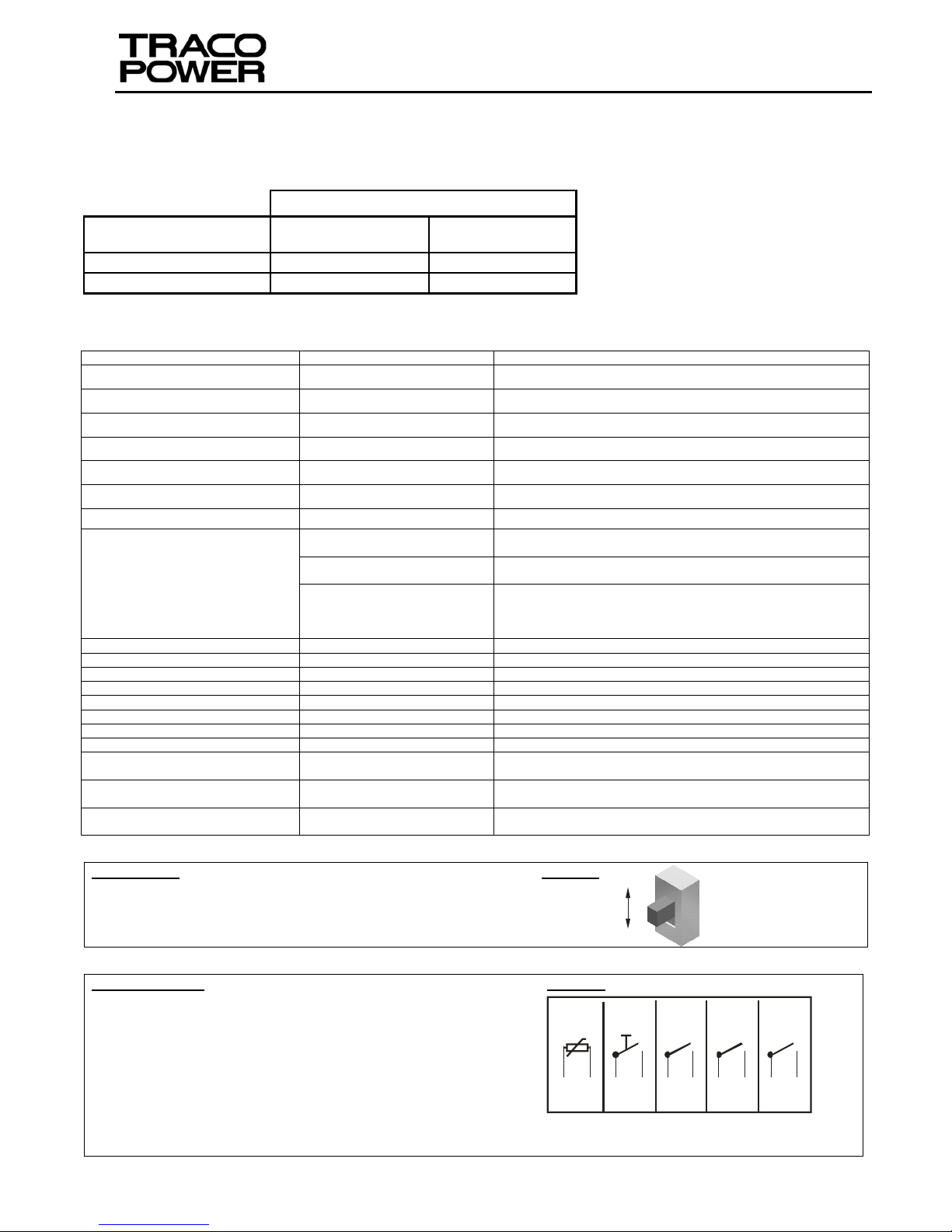
User Settings: Figure 1:
Battery Test Interval:
15 seconds or 10 minutes user selectable with switch
Signal Connector: Remark: Tightening torque 0.19Nm for all contacts. Figure 2:
Temp.Sensor: Connect external sensor for automatic end of charge
battery compensation.
Battery Remote ON/OFF: Enables remote disconnection of the
battery.
DC OK: Closed contact indicate that the output voltage is higher
than 82-90% of the nominal output voltage (24V).
BAT OK: Closed contact indicates that the battery is charged and
has low resistance (100mΩ max). During battery operation, open contacts indicate
that the battery is approaching (within approx.. 1V) the disconnection voltage level.
AC-IN-OK: Closed contact when the AC supply voltage is present. Open contacts indicate loss of AC Supply Voltage or overload at low AC supply
voltage levels.
Parameter Condition Settings
Nominal AC Input Range [VAC] High line 220-240
Input AC Voltage Range [VAC] High line 187-264
Nominal AC Input Range [VAC] Low line 100-120
Input AC Voltage Range [VAC] Low line 85-132
Input Frequency Range [Hz] 47 - 63
Output Voltage [V] Normal Mode 24.0-26.0V (adjusted by POT)
Output Voltage [V] Buffer Mode 23.4-23.8V (Internally set)
Electrical Connections
& Wire Size
AC Supply Input
1 - 4 mm
2
[AWG17-AWG11]
Tightening Torque 0.6Nm
DC Output
2 - 10 mm
2
[AWG14-AWG7]
Tightening Torque 1.76Nm
Battery Input
2.5 - 10 mm
2
[AWG13-AWG7] Nominal Power
4 - 10 mm
2
[AWG11-AWG7] Boost Power
max. resistance 10mΩ
Tightening Torque 1.76Nm
Battery Charging Current [A] Normal Mode 0.8…1.2
Nominal Battery Voltage [V] 25°C Ambient 13.6 (Factory Set)
Battery Adjustment Range [V] Normal Mode 13.0…14.4
Battery Test Current [A] Normal Mode 2.5A for 60ms (typ)
Battery Test Interval [s] Normal Mode 15s or 8..10mins (Set by switch: Fig.1)
Battery Warning Voltage [V] Buffer Mode 10.4...11.4
Battery Disconnection Voltage [V] Buffer Mode 9.1…10.2
Thermal Protection Buffer Mode 100°C (at back of chassis)
Automatic Battery Temperature
Compensation Range
Normal Mode -15°C…50°C (external sensor temp. Fig.2)
Battery Remote ON/OFF Buffer Mode
Switch 5V/5mA (min) to GND (Fig.2)
Level: 0…0.5V
Signal Relay Contact Rating
(Resistive Load)
Signal Monitoring 60VDC 0.5A (Fig.2)

http://www.tracopower.com Rev:1.0 / 1615
Safety Instructions:
¾ Before installation read these instructions carefully and com-
pletely. This installation instruction cannot account for every
possible condition of installation, operation or maintenance.
Further information can be obtained from your local distributor
office or from the product datasheet, which can be
downloaded from our website:
www.tracopower.com/products/tspc240ups.pdf
¾ Before any installation, maintenance or modification work
ensure that the main switch is switched off and prevented
from being switched on again. Non-observance, touching of
any live components or improper handling of this power
supply can result in death, severe personal injury or
substantial property damage. Proper and safe operation is
dependent on proper storage, handling, installation and
operation.
¾ Compliance with the relevant national regulations (in the USA,
Europe and other countries) must be ensured. Before
operation is started the following conditions must be ensured:
By use of stranded wires, all strands must be fastened in
the terminal blocks. (Potential danger of contact with the
case)
Power supply and mains cables must be sufficiently fused.
All output wires must be rated for the equipment output
current and must be connected with the correct polarity.
Sufficient cooling must be ensured.
¾ Never work on the equipment if power is supplied! Risk of
electric arcs and electrical shock, which can cause death,
severe personal injury or substantial property damage.
¾ Warning: Hazardous voltages and components storing a very
substantial amount of energy are present in this power supply
during normal operating conditions. However, these are
inaccessible. Improper handling may result in an electric
shock or serious burns! Do not open the equipment until at
least 5 minutes after it has been disconnected from the
power supply on all po les.
Only trained personnel may open the equipment.
Do not introduce any objects into the equipment.
Adjustment potentiometer(s) may only be actuated using
an insulated screwdriver.
Keep away from fire and water
Pollution degree 2 environment
CAUTION: “FOR USE IN A CONTROLLED ENVIRONMENT”
Installation Instructions:
¾ This equipment is designed for professional indoor
systems. In operation the equipment must not be
accessible. It may be installed and put into service by
qualified personnel only.
¾ The correct mounting position for optimal cooling
performance must be observed. Do not cover any
ventilation holes. Leave a free space of minimum 80mm
(3.15in.) above and below the power supply and on each
side of the power supply a minimum space of 25mm
[0.98in] which allows air convection. Observe power
derating.
¾ ATEX: To comply with the ATEX directive following
installation instructions have to be observed:
These power supplies are constructed in accordance
with the safety requirements of EN60079-0:2012 &
EN60079-15:2010, Ex nA nC IIC T4 Gc.
These power supplies units can be installed in switch
cabinets or protective housings that meet the
requirements of EN 60079-15 or if applicable EN
60079-0 (housing protection type min. IP54)
The permissible ambient temperature range is -20°C to
+70°C. Observe load derating.
For installation in switch cabinets or in protective
housings, it must be ensured that the stipulated
maximum temperatures are not exceeded on these
power supplies.
Do not operate voltage adjustment, unless area is
known to be non-hazardous.
The power supply units are Unit Group II Category 3G
components (ex components) as defined by RL
94/9/EG (ATEX 95) Appendix I. A separate conformity
on the end-equipment which contains these
components evaluation process must be performed.
For use / Installation also the requirements defined in
EN60079-14 must be observed.
¾ Recycling: The unit contains elements that are suitable for
recycling, and components that need special disposal. You
are therefore requested to make sure that the power
supply will be recycled environment friendly at the end of
its service life.
 Loading...