

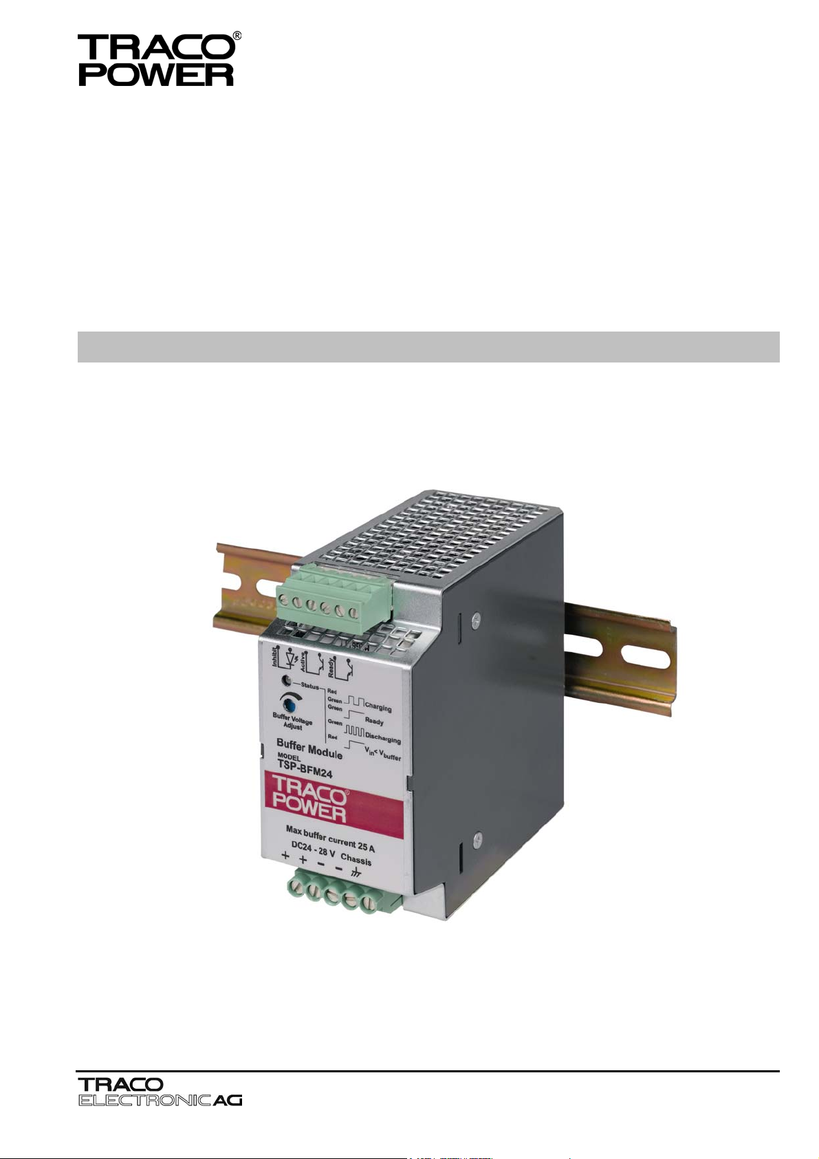
BUFFER MODULE TSP-BFM24
Operating Instructions
Jenatschstrasse 1
CH-8002 Zürich
Tel: +41 43 311 4511
Fax: +41 43 311 4545
sales@traco.ch
www.tracopower.com
Date: 24 May 2005
Issue: 1.2
Page
Seite
1
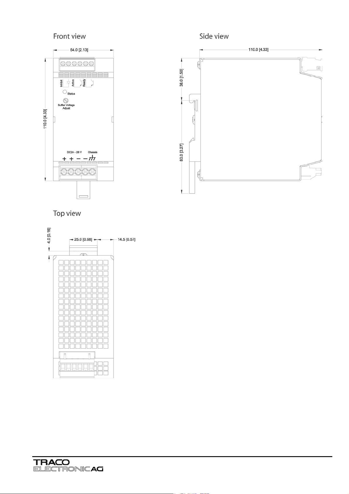
Dimensions drawings:
TSP-BFM24
Weight: 1.59lb
Gewicht: 0.72kg
Note
This instruction cannot claim all details of possible equipment variations, nor in particular can they provide for every possible
example of installation, operation or maintenance. Further information is available from your local distributor office or from the
TSP industrial power supply data sheet. Subject to change without prior notice.
In order to guarantee safe operation of the TSP-BFM24 in combination with the TSP power supplies and to be able to
make use of all the functions, please read these instructions thoroughly!
Jenatschstrasse 1
CH-8002 Zürich
Tel: +41 43 311 4511
Fax: +41 43 311 4545
sales@traco.ch
www.tracopower.com
Date: 24 May 2005
Issue: 1.2
Page
Seite
2
English
A
p
r
Warning
The TSP-BFM24 is constructed in accordance with the safety requirements of IEC 60950, EN60950, UL60950 and UL508.
The TSP-BFM24 fulfils the requirements for CE-compatibility and carries the CE-mark and is UL & cUL approved by CSA.
The TSP-BFM24 built-in module is designed especially for use in process automation and other industrial applications.
Components with dangerously high voltage and high stored energy are located in the device. However, these are inaccessible.
Failure to properly maintain the TSP-BFM24 can result in death, severe personal injury or substantial property damage. The
TSP-BFM24 may o
regulations (e.g. UL, ANSI, VDE, DIN) must be observed. The successful and safe operation of this module is dependent on
proper storage, handling, installation and operation.
The potentiometer to adjust the TSP-BFM24 threshold level is only allowed to be actuated using an insulated screwdriver,
because accidental contact may be made with parts inside the power supply carrying dangerous voltages.
nly be installed and put into operation by qualified personnel. The corresponding national
Please observe following points before putting the device into operation:
• Read operating instructions thoroughly.
• That the installation has been carried out by a competent person and protection against electrical shock is guaranteed!
• That the input wiring is sufficiently dimensioned!
• That the output wiring is dimensioned according to the maximum output current or separately protected!
• That the protective earth is connected.
• Sufficient cooling is guaranteed!
• The temperature of the housing can become very high, depending on the ambient temperature and load.
Caution:
Risk of electrical shock and electrical discharge. The TSP-BFM24 nor the power supply must not be opened until at least 5
minutes after complete disconnection of the mains and battery.
Electrostatic sensitive device.
Qualified and trained personnel only may open the TSP-BFM24 or the power supply.
ttention: In case of non-observance or exceeding the mentioned limiting value of the data sheet, the function
and electrical safety can be impaired and can destroy the TSP-BFM24 and/or the power supply.
Before installation ensure that the main switch is switched off and prevented from being
switched on again. In case of non-observance, touching of any live components or imprope
dealing with this TSP-BFM24 or power supply can result in death or fatal injury.
Danger: Never work on the TSP-BFM24 or
ower supplies if power is applied!
1. Description and construction
The TSP-BFM24 Buffer Module will hold the output voltage of a 24VDC power supply after brown outs or voltage dips of up to
ten full 50Hz cycles. During this buffer period no deterioration of the 24VDC output voltage will occur. For many applications this
buffer module is an ideal and cost effective alternative to a battery based backup system. The buffer module consists of a large
bank of capacitors. When the power supply is switched on, the buffer capacitors will be charged. This will take approximately 30
second and an opto-coupler signal indicates the "READY" condition. When a power fail occurs, the capacitor bank is
discharged, maintaining the output of the buffer module at its nominal voltage. This condition is indicated by a "POWER FAIL"
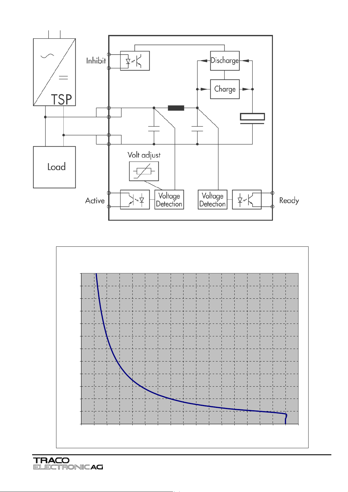
signal. The hold up time is typically 200ms at 25A and 4 seconds typically at 1,2A. After 4 seconds the buffer device will switch
off the output voltage. The operation modes of the module are indicated by a LED on the front panel also. The big advantage of
this buffer solution is, that it is fully maintenance free and its storage capability does not deteriorate over the lifetime of the
product.
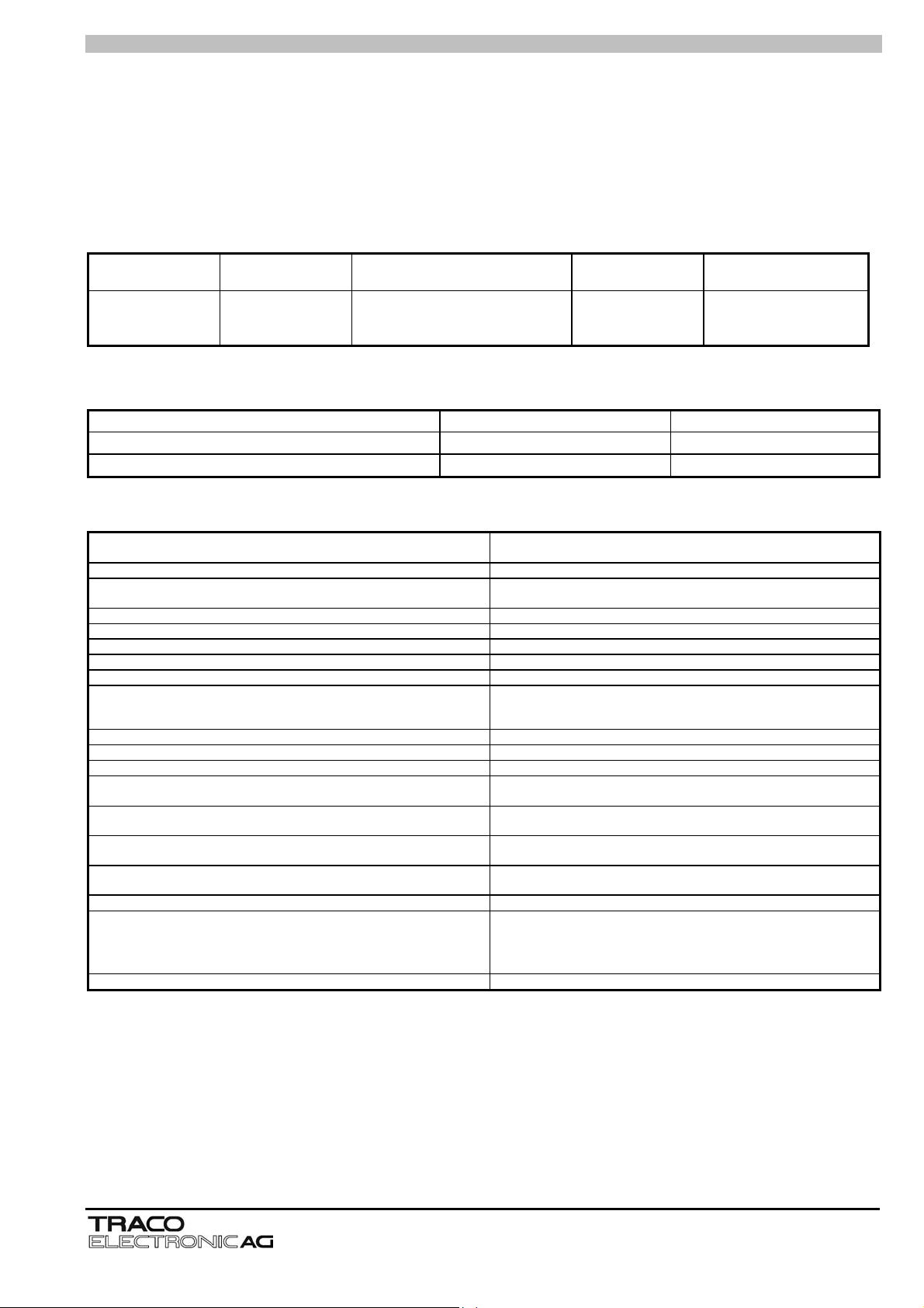
The TSP power supply has to be connected to the load as well as to the TSP-BFM24 module (see Fig. 1.1). The device is in
parallel to the output voltage of the TSP power supply, and charges its internal hold-up capacitors during normal operation. The
charge current (<0.6A) is taken from the power supply output itself (charging time 30 sec max.). The output voltage is monitored,
if it drops below an adjusted threshold the TSP-BFM will switch off. The stored energy in the hold-up capacitors is used to keep
the output voltage at the threshold level. The quiescent current is 100mA typ. (typ. 2.5W). The output voltage of the TSP power
supply has to be 1V higher as the threshold level adjusted by the potentiometer (see Fig. 3.1)
The threshold level can be adjusted on two different ways:
Option 1: In the factory the TSP-BFM24 is charged and then discharged with no load, this gives the operator 4s approx. to set
the threshold level.
Option 2: Less accurate. Turn the TSP-BFM24 Potentiometer fully clockwise and connect the TSP-BFM24 to a DC supply or
the TSP power supply unit set to 22.5V (for 24Vdc output voltage use) or to the level which the threshold level should
be set. Turn the Buffer Pot anti-clockwise until the charging LED starts flashing Green/Red
The TSP-BFM24 is a built-in unit. The mounting position has to fulfil the requirements for fireproof case according to UL60950,
IEC/EN 60950 or other appropriate national standard. The relevant UL regulations or equivalent national regulations must be
observed during installation.
The TSP-BFM24 is designed for mounting on a DIN rail TS35 (DIN EN 50022-35x15/7.5).
against reverse input polarity.
The TSP-BFM24 is not protected
Jenatschstrasse 1
CH-8002 Zürich
Tel: +41 43 311 4511
Fax: +41 43 311 4545
sales@traco.ch
www.tracopower.com
Date: 24 May 2005
Issue: 1.2
Page
Seite
3
English
2. Installation
A sufficiently strong DIN-rail has to be provided. The correct mounting position for optimal cooling performance must be
observed. Above and below the TSP-BFM24 a minimum free space of 80mm [3.15in] is required and on each side of the TSPBFM24 a minimum space of 50mm [1.97in] is required which allows air convection. The air temperature measured 10mm
[0.39in] below the device must not exceed the specified values in the data sheet. Observe power derating above ambient
temperatures of 40°C as specified for the TSP power supplies.
2.1 Assembly
To fix unit on the DIN-rail, hook top part of clip on DIN-rail, push down and inward until you hear a clipping sound.
To remove the unit, pull the latch of the clip with the aid of an insulated flat head screwdriver. When clip has cleared bottom DIN
rail remove the screwdriver from recess. Lift the unit off DIN-rail.
Wall mounting or chassis mounting can be achieved by use of optional mounting bracket TSP-WMK01 (1 bracket, see Fig. 3.1).
Remove the DIN-clips by removing the screw and place the mounting brackets in the same place as the DIN-clips. Use the
countersink screws, which are included with the wall mounting kit (1 countersink screw with TSP-WMK01) to fix the mounting
brackets on the TSP-BFM24 (tightening torque 0.8-0.9Nm).
2.2 Connecting cable
Only qualified personnel may carry out the installation. The device is equipped with COMBICON connector and
COMBICON plug connectors (Signals). This reliable and easy-to-assemble connection method enables a fast connection of the
device.
2.2.1 Input (Fig. 3.1 Î Connector J1, pin 1, pin 2, pin 3, pin 4 & pin 5):
The connection is made by using the –Vin and +Vin connections (see Fig. 3.1 Î Connector J1, pin 1, pin 2, pin 3 and pin 4) as
well as protective earth (see Fig. 3.1 Î Connector J1, pin 5) and has to be carried out in accordance with the local regulations.
Sufficiently dimensioned wiring has to be ensured (see chapter 2.2.1.1) or has to be separately protected.
To achieve a reliable and shockproof connection strip the connecting ends according chapter 2.2.1.1. If flexible wires are used
the wires have to be terminated. (e.g. by using ferrules)
2.2.1.1 Connections and terminal assignment
Unit Terminals Function
TSP 090-124
TSP 180-124
TSP 360-124
TSP 600-124
+ & - Input Voltage (24VDC) 0.5 … 2.5 24 … 12 0.5 – 0.6 7.0
Signal Inhibit, active and ready signal 0.2 … 2.5 32 … 12 0.5 – 0.6 7.0
+ & - Output Voltage (24VDC) 1.0 … 2.5 18 … 12 0.5 – 0.6 7.0
Signal Inhibit, active and ready signal 0.2 … 2.5 32 … 12 0.5 – 0.6 7.0
+ & - Output Voltage (24VDC) 2.0 … 4.0 12 … 10 0.5 – 0.6 8.0
Signal Inhibit, active and ready signal 0.2 … 2.5 32 … 12 0.5 – 0.6 7.0
Protective Earth Conductor 0.5 … 2.5 24 … 12 0.5 – 0.6 7.0
Protective Earth Conductor 0.5 … 2.5 24 … 12 0.5 – 0.6 7.0
Protective Earth Conductor 1.0 … 4.0 18 … 10 0.5 – 0.6 7.0
Solid or stranded wires Torque Stripping length
2
[mm
] [AWG] [Nm] [mm]
2.2.2 Signalling (Fig. 3.1Î Connector J2, pin 3, pin 4, pin 5 & pin 6):
The output “Active” is for enabling monitoring of the functions if the TSP-BFM24 is in operation. This signal is detected by
measuring the input voltage direct at the input pins and is provided by an open collector opto coupler which can handle 10mA in
maximum (see also Fig 1.1 and Fig. 3.1 Î connector J2, pin 3 & pin 4). The output “Ready” is providing the signal if the TSPBFM24 is ready to provide the current (see Fig. 3.1 Î Connector J2, pin 5 & pin 6). The “Ready” signal is provided by an open
collector opto coupler which can handle 28Vdc/10mA. It is detected by measuring the TSP-BFM24 voltage level direct at the
capacitors (see Fig. 1.1).
2.2.2.1 Status LED:
The Status LED is a two colour LED which indicates the status of the TSP-BFM24 module and enables visual evaluation of the
function locally in the control cabinet. Status LED green – normal operation, TSP-BFM24 is ready to provide a current of 25A
max.. Status LED red – input voltage on the TSP-BFM24 is lower as the adjusted threshold level. Status LED is changing from
green to red – TSP power supply is charging the TSP-BFM24 module. Status LED green pulsing – TSP-BFM is providing output
current, discharging of TSP-BFM24.
3. Function
3.1 Inhibit:
The TSP-BFM24 unit provides an Inhibit function by use of pin 1 & pin 2 at connector J2 (see Fig. 3.1) to control the TSPBFM24 module. To switch off the TSP-BFM24 a voltage level between 5Vdc and 28Vdc has to be applied on Connector J2 pin 1
(Inhibit GND) and Connector J2, pin 2 (Inhibit +). At open connection or a voltage level between 0Vdc and 1Vdc between J2 pin
1 (Inhibit GND) and pin 2 (Inhibit +) the device is ready to provide the output current for the requested buffer time.
Jenatschstrasse 1
CH-8002 Zürich
Tel: +41 43 311 4511
Fax: +41 43 311 4545
sales@traco.ch
www.tracopower.com
Date: 24 May 2005
Issue: 1.2
Page
Seite
4
English
4. Compliance to UL508C
The TSP-BFM24 is a is a built-in device and to comply with UL508C the device must be installed in a cabinet with minimum
dimensions of: 400mm (Width) x 500mm (Height) x 200mm (Depth)
4.1 Operating Temperature Ranges and load derating:
Depends on the TSP connected to the TSP-BFM24. Please see operating temperature range and load derating at the TSP
power supply datasheet or TSP operating instructions.
5. Technical Specifications
4.1 Input Specifications
Order code
Input Buffer Time
Depending on load (see Fig. 2.1)
TSP-BFM24 24 Vdc
200 msec @ 25A load
4 sec @ 1.2A load
* Output voltage adjustable
** Maximum current at Vout nom.
5.2 Output Specifications
Threshold adjustable Range with Potentiometer 22 - 28 Vdc
Ripple and Noise (20MHz Bandwidth) at V
Parallel operation
in nom
und I
* Operating Voltage
22 - 28 Vdc 25.0 A (600W)
200mV pk-pk max
out max
2 devices possible
max. Output Current
5.3 General Specifications
Operating Temperature Range -25°C … +70°C
Cooling Convection cooling; no internal fan
Storage Temperature Range -25°C … +85°C
Load Derating above +40°C (104°F) According the load derating of TSP xxx-124 used
Humidity (non condensing) 95% rel H max.
Pollution Degree 2
Temperature Coefficient 0.02%/K
Reliability, calculated MTBF in accordance to IEC 61709 >350'000 hours
Inhibit see Fig. 3.1 see Fig. 3.1; J2 pin 1 (GND) & pin 2 (+)
Alarm Outputs 28Vdc / 10mA
Case protection in accordance to IEC 529 IP20
Isolation See Safety Standards
Safety Standards according to
Electromagnetic compatibility
(EMC) Emissions
Electromagnetic compatibility
(EMC) Immunity
Environment Vibration
Enclosure Material Aluminium (Chassis) / Zinc plated Steel (Cover)
Mounting DIN-Rail mounting
Connection Screw terminal and pluggable screw terminal (plug included)
- Information Technology Equipment
- Industrial Control Equipment
Shock
Wall mounting
-13°F … +158°F
-13°F … +185°F
if a voltage level of 5Vdc to 28Vdc is applied Î Device off
if a voltage level of 0Vdc to 1Vdc is applied Î Device on
IEC / UL / EN 60950
UL 508C
in correspondence to connected units (no internal switching device)
in correspondence to connected units (no internal switching device)
IEC 60068-2-6 3 axis, sine sweep, 10 … 55Hz, 1g, 1oct/min.
IEC 60068-2-27 3 axis, 15g, half sine, 11ms
For DIN-Rails as per EN 50022-35 x 15 / 7.5
(snap-on self-locking spring)
With wall mounting bracket option TSP-WMK01 for TSP-BFM24
(see datasheet page 7)
Jenatschstrasse 1
CH-8002 Zürich
Tel: +41 43 311 4511
Fax: +41 43 311 4545
sales@traco.ch
www.tracopower.com
Date: 24 May 2005
Issue: 1.2
Page
Seite
5
Block diagram TSP-BFM24
J2.2
J2.1
J1.1
J1.2
J1.3
J1.4
J2.4
J2.3
TSP-BFM24 – Buffer Time vs. Load Power
TSP-BFM24 - Buffer Time vs Load Power (typical values)
J2.6
J2.5
Fig. 1.1
600
550
500
450
400
350
300
250
Load Power [W]
200
150
100
50
0
0 0.25 0.5 0.75 1 1.25 1.5 1.75 2 2.25 2.5 2.75 3 3.25 3.5 3.75 4 4.25
Fig.: 2.1
Time [s]
Jenatschstrasse 1
CH-8002 Zürich
Tel: +41 43 311 4511
Fax: +41 43 311 4545
sales@traco.ch
www.tracopower.com
Date: 24 May 2005
Issue: 1.2
Page
Seite
6
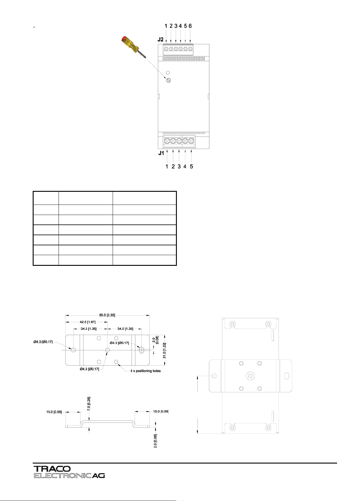
Connectors of TSP-BFM24
Pin 1
Pin 2
Pin 3
Pin 4
Pin 5
Pin 6
J1 J2
+Vin Inhibit GND
+Vin Inhibit +
-Vin Active GND
-Vin Active Signal
FG Ready GND
- Ready Signal
Wall mounting brackets (TSP-WMK01) for TSP-BFM24
)
6
1
.
2
(
0
.
5
5
Fig.: 3.1
Fig.: 4.1
Jenatschstrasse 1
CH-8002 Zürich
Tel: +41 43 311 4511
Fax: +41 43 311 4545
sales@traco.ch
www.tracopower.com
Date: 24 May 2005
Issue: 1.2
Page
Seite
7
 Loading...