

TRACO POWER TSP-BCM24 Operating Instructions Manual
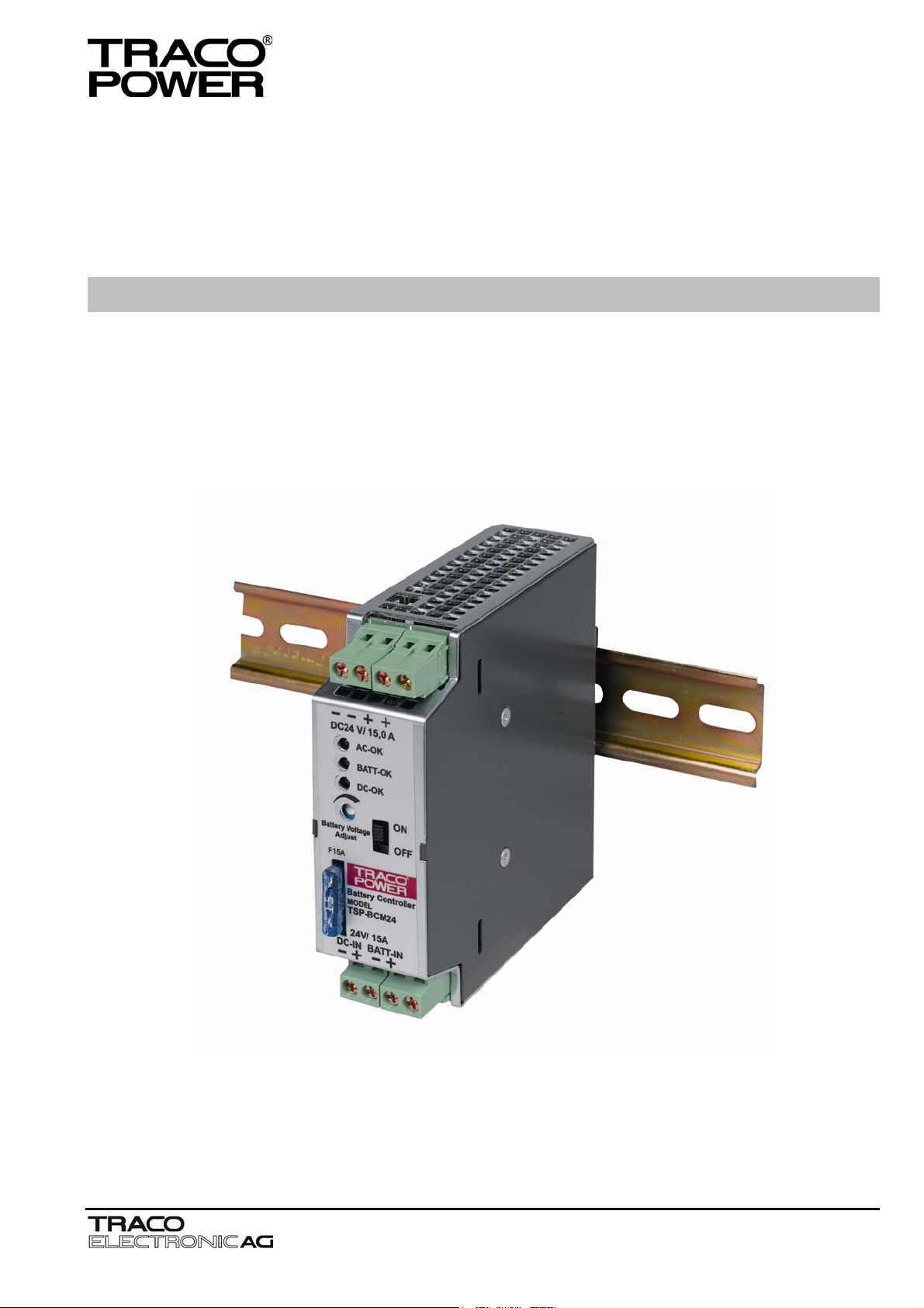
BATTERY CONTROLLER MODULE TSP-BCM24
Operating Instructions
Jenatschstrasse 1
CH-8002 Zürich
Tel: +41 43 311 4511
Fax: +41 43 311 4545
sales@traco.ch
www.tracopower.com
Date: 19 October 2006
Issue: 1.3
Page
Seite
1
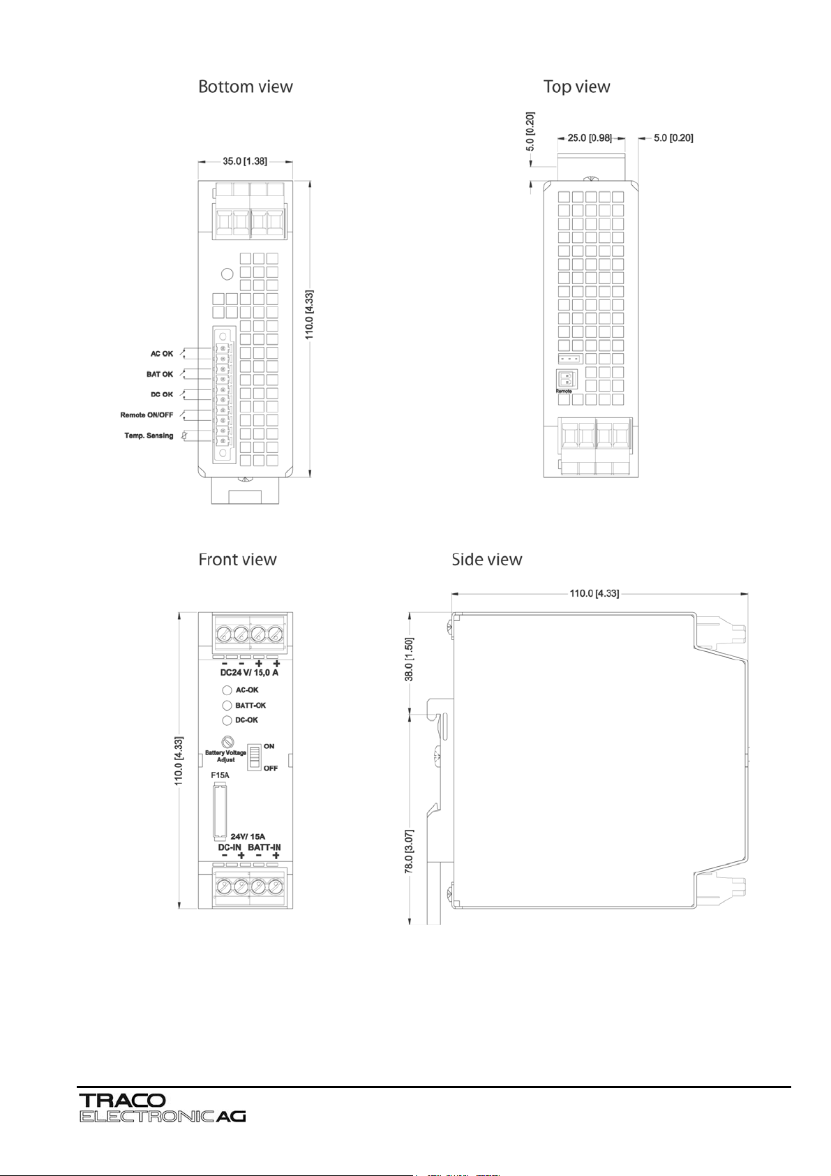
Dimensions drawings:
g
TSP-BCM24
Weight: 0.816lb
Gewicht: 0.37k
Note
This instruction cannot claim all details of possible equipment variations, nor in particular can they provide for
every possible example of installation, operation or maintenance. Further information is available from your local
distributor office or from the TSP industrial power supply data sheet. Subject to change without prior notice.
In order to guarantee safe operation of the TSP-BCM24 in combination with the TSP power supplies and
to be able to make use of all the functions, please read these instructions thoroughly!
Jenatschstrasse 1
CH-8002 Zürich
Tel: +41 43 311 4511
Fax: +41 43 311 4545
sales@traco.ch
www.tracopower.com
Date: 19 October 2006
Issue: 1.3
Page
Seite
2
English
y
t
A
y
r
Warning
The TSP-BCM24 is constructed in accordance with the safety requirements of IEC 60950, EN60950, UL60950,
UL508, IEC/EN60079-15 (Class I, Zone 2, AEX nC II C T4 U) and UL 1604 (Class I, Div. 2, Groups A, B, C and D).
The TSP-BCM24 fulfils the requirements for CE-compatibility and carries the CE-mark and is UL & cUL approved b
CSA.
The TSP-BCM24 built-in module is designed especially for use in process automation and other industrial
applications.
Components with dangerously high voltage and high stored energy are located in the device. However, these are
inaccessible. Failure to properly maintain the TSP-BCM24can result in death, severe personal injury or substantial
property damage. The TSP-BCM24 may only be installed and put into operation by qualified personnel. The
corresponding national regulations (e.g. UL, ANSI, VDE, DIN) must be observed. The successful and safe operation
of this module is dependent on proper storage, handling, installation and operation.
The potentiometer to adjust the output voltage is only allowed to be actuated using an insulated screwdriver, because
accidental contact may be made with parts inside the power supply carrying dangerous voltages.
Please observe following points before putting the device into operation:
• Read operating instructions thoroughly.
• That the input wiring is sufficiently dimensioned!
• That the output wiring is dimensioned according to the maximum output current or separately protected!
• Sufficient cooling is guaranteed!
• The temperature of the housing can become very high, depending on the ambient temperature and load.
Caution:
Risk of electrical shock and electrical discharge. The TSP-BCM24 nor the power supply must not be opened until a
least 5 minutes after complete disconnection of the mains and battery.
Electrostatic sensitive device. Qualified and trained personnel only may open the TSP-BCM24 or the power
ttention: In case of non-observance or exceeding the mentioned limiting value of the data sheet, the function
and electrical safety can be impaired and can destroy the TSP-BCM24 and/or the power supply.
Before installation ensure that the main switch is switched off and prevented from being
switched on again. In case of non-observance, touching of any live components or imprope
dealing with this TSP-BCM24 or power supply can result in death or fatal injury.
Danger: Never work on the TSP-BCM24 or power supplies if power is applied
or if the batter
is still connected!
1. Description and construction
The module TSP-BCM24 provides a professional battery management system to charge and monitor an external lead-acid battery (e.g.
YUASA NP batteries). Together with a power supply of the TSP series (TSP 090-124, TSP 180-124 and TSP 360-124) a perfect DC-UPS
system can be configured. The connected battery will be charged and held in charge mode by the power supply. In the event of a power
failure the battery will supply the output power until the battery is discharged. As a consequence, the output voltage of the system is
equivalent to the battery voltage.To avoid overcharging the battery, an external temperature sensor adjusts the battery voltage
automatically to the required end of charge voltage. This achieves a long battery life time.
The battery is protected against deep discharge. Mains power and the battery status are monitored regulary and failures indicated by
LED’s and signal outputs.
Before connecting the input, output and sense lines (see Fig. 2.1 and Fig 3.1; J1, J2 and J3) the potentiometer on the TSP power supply
has to be turned completely conterclockwise (V
BCM24 (see Fig. 3,1, J1 and chapter 2.2.1) as well as the remote sensing between these two devices using the wire supplied with the
TSP-BCM module (see Fig. 2.1 and Fig. 3.1, J3). Before connecting the battery the battery charging voltage has to be adjusted as
recommended by the battery manufacturer. Further the Jumper J6 has to be set according to the TSP which is connected to the TSPBCM24 module (see Fig. 3.1 J6 and chapter 3.4). Than the battery can be connected to the Batt In connector (see Fig. 3.1, J1 and chapter
2.2.2). Now connect the load to DC-Out (see Fig. 3.1, J2 and chapter 2.2.3).
The TSP-BCM24 is a built-in device. The mounting position has to fulfil the requirements for fireproof case according to UL60950, IEC/EN
60950 or other appropriate national standard. The relevant UL regulations or equivalent national regulations must be observed during
installation.
The TSP-BCM24 is designed for mounting on a DIN rail TS35 (DIN EN 50022-35x15/7.5).
The output voltage of the TSP-BCM24 is protected against short circuit and open circuit conditions.
). Afterwards the connection between the TSP (TSP xxx-124) and DC In on the TSP-
out min
2. Installation
A sufficiently strong DIN-rail has to be provided. The correct mounting position for optimal cooling performance must be observed. Above
and below the TSP-BCM24 a minimum free space of 80mm [3.15in] is required and on each side of the TSP-BCM24 a minimum space of
50mm [1.97in] is required which allows air convection. The air temperature measured 10mm [0.39in] below the device must not exceed the
specified values in the data sheet. Observe same power derating above ambient temperatures of 40°C as specified for the TSP power
supplies.
Jenatschstrasse 1
CH-8002 Zürich
Tel: +41 43 311 4511
Fax: +41 43 311 4545
sales@traco.ch
www.tracopower.com
Date: 19 October 2006
Issue: 1.3
Page
Seite
3
 Loading...