

TRACO POWER TMSB 2 Series, TMSB 2-114, TMSB 2-108, TMSB 2-124, TMSB 2-283 Installation Information
...
INSTALLATION INFORMATION
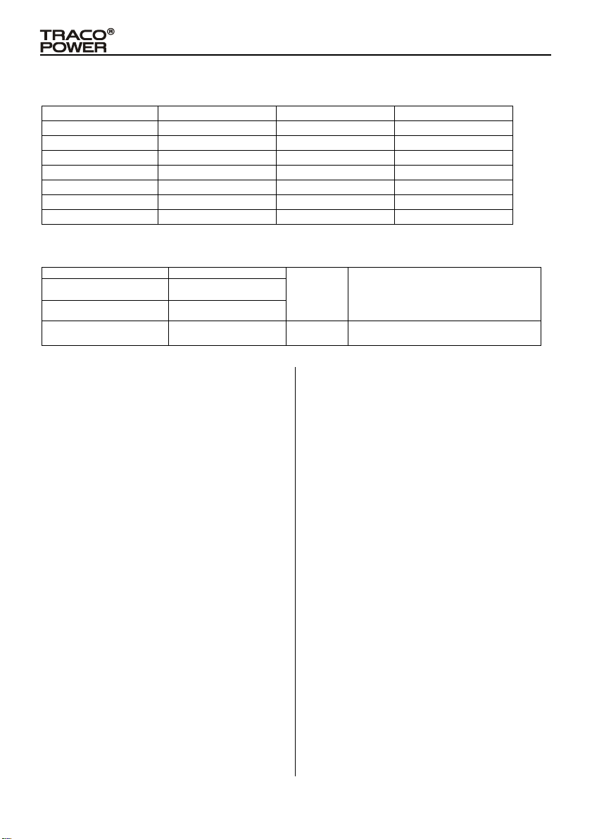
TMSB-2 Series AC/DC POWER MODULE
Order Code Output Power max. Output 1(Vo1/Io1) Output 2(Vo2/Io2)
TMSB 2-108 2 Watts 8Vdc / 250mA --TMSB 2-114 2 Watts 14Vdc / 143mA --TMSB 2-124 2 Watts 24Vdc / 83mA --TMSB 2-283*** 2 Watts 8Vdc / * 3.3Vdc /160mA
TMSB 2-285*** 2 Watts 8Vdc / * 5Vdc /250mA
TMSB 2-2143*** 2 Watts 14Vdc / ** 3.3Vdc /70mA
TMSB 2-2145*** 2 Watts 14Vdc / ** 5Vdc /83mA
*Io1+Io2≦250mA
**Io1+Io2≦143mA
***The definition of output power (Po) for dual output modules: Po=Vo1 X (Io1+Io2)
Input Voltage Range: 85-264VAC / 50-60Hz
Input Current:
Operation Temperature Range: -30℃~+70℃ Max.
Internal Fuse: T1A 250VAC Min.
50mA typ. at Vin = 115VAC
30mA typ. at Vin = 230VAC
Safety Instructions:
¾ Before installation read these instructions carefully and completely.
This installation instruction cannot claim for every possible example
of installation, operation or maintenance. Further information’s are
obtainable from your local distributor office or from the product data
sheet which can be downloaded from the Internet at
http://www.tracopower.com
¾ The power supplies are constructed in accordance with the safety
requirements of cUL/UL/IEC/EN60950-1 and IEC/EN60335-1. They
fulfil the requirements of the Low Voltage Directive (L VD) and car ries
the CE-mark. UL and cUL are approved in accordance to UL60950-1,
and TUV is approved in accordance to IEC/EN60335-1.
¾ Before an installation, maintenance or modification work ensure that
the main switch is switched off and prevented from being switched
on again. In case of non-observance touching at any alive
components or improper dealing with this power supply can result in
death, severe personal injury or substantial property damage. The
successful and safe operation is dependent of proper storage,
handling, installation and operation.
¾ Compliance with the relevant national regulations (in the USA,
Europe and the other countries) must be observed and ensured.
Before operation is started the following conditions must be ensured:
Connection to mains supply in compliance with national
regulations (VDE0100 and EN50178).
By use of stranded wires, all strands must be fastened in the
terminal blocks.
Power supply and mains cables must be sufficiently fused.
All output wires must be rated for the power supply output current
and must be connected with the correct polarity.
Sufficient cooling must be ensured
Keep away from fire and water
¾ Never work on the power supply if power is supplied! Risk of
electric arcs and electrical shock which can cause death, severe
personal injury of substantial property damage.
Sihlbruggstrasse 111 CH-6340 Baar, Switzerland
Terminal for
Wiring:
Case Material:
¾ Warning: Hazardous voltages and components storing a very
¾ For the assembly information of chosen AC/DC Power Module, see
◆ Avertissement:Ce bloc d’alimentation contient une grande
◆ Pour assembler ce module d’alimentation CA/CC, veuillez
PCB mounting with solder pin’s.
Plastic Resin
UL 94V-0 flammability rating
substantial amount of energy are present in this power supply during
normal operating conditions. However, these are inaccessible.
Improper handling may result in an electric shock or serious burns!
the AC/DC Power Module specification and rating label for details:
Make sure the dimensions of location for assembly complying with
category or specification datasheet.
Do not expose the AC/DC Power Module to excessive heat,
moisture, dust, or corrosive gases.
The overall dimensions of AC/DC Power Module shall be
assembled according to the ventilation designs of end-use
product.
Do not open the power supply until at least 5 minutes after it
has been disconnected from the mains on all poles.
tension et des composants puissants pendant l’utilisation
normale. Une mauvaise manipulation peut causer un choc
électrique ou des brûlures graves !
vous référer aux spécifications et la plaque signalétique du
module CA/CC :
◆La dimension de l’endroit de l’assemblage doit correspondre
à la catégorie ou aux spécifications.
◆Il ne faut pas exposer ce module d’alimentation CA/CC à la
chaleur, à l’humidité, à la poussière ou aux gaz corrosifs.
◆La dimension générale du module CA/CC doit respecter le
système de ventilation du produit fini.
Avant d’ouvrir le bloc d’alimentation, attendre au moins 5
minutes après la déconnexion de tous les pôles
Issued: JUNE 9th, 2014 / Rev.:2
Installation Instructions:
¾ This power supply is desig ned for professio nal i ndoor systems.
In operation the power supply must not be accessible. It may
be installed and put into service by qualified personnel only.
¾ The correct mounting position for optimal cooling performance
must be observed. Observe power derating. (see data sheet)
¾ Recycling: The unit contains elements which are suitable for
recycling, and components which need special disposal. You
are therefore requested to make sure that the power supply
will be recycled by the end of its service life.
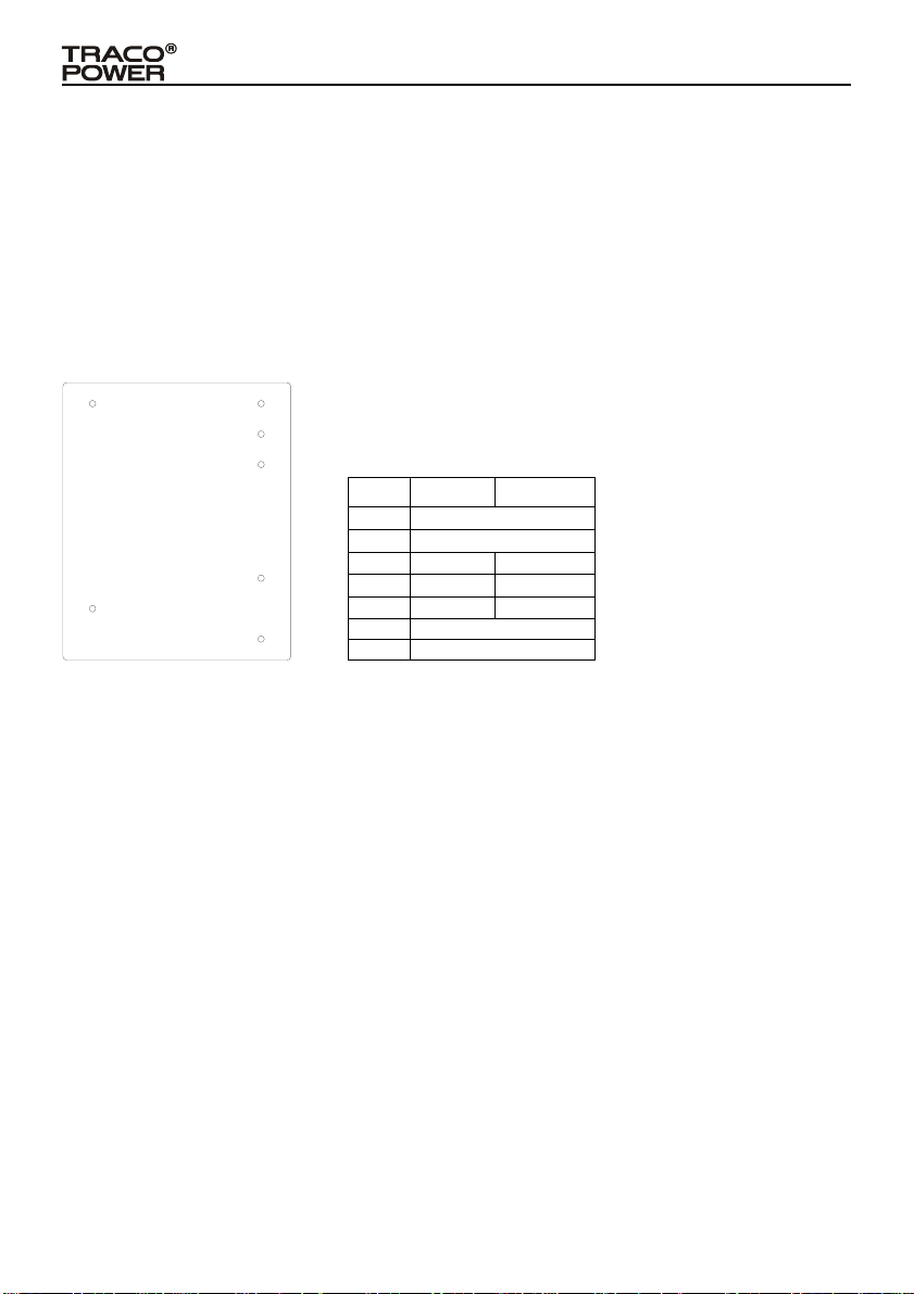
Wiring Terminals Diagram:
23
4
5
Bottom View
6
1
7
Pin Connections
Pin
Single
1
2
+Vout
3
-
4
5
6
7
Vout
NP
Dual
NC
NC
+Vout1
Common
+Vout2
AC(N)
AC(L)
Sihlbruggstrasse 111 CH-6340 Baar, Switzerland
Issued: JUNE 9th, 2014 / Rev.:2
 Loading...