

TRACO POWER TEX 120-112, TEX 120-124 Installation Instructions Manual
http://www.tracopower.com
Rev: 5.6/4915
INSTALLATION INSTRUCTIONS
TEX 120 Series Industrial Power Supply
Table 1
Order Code
Rated Input
Voltage
Output
Power max.
Output
** Output Voltage
Adjustment Range
recommended Circuit
breaker (Characteristic C)
TEX 120-112
100 – 240Vac
50 / 60Hz
Universal Input
96 Watt
12.0VDC / 8.0A
12.0 – 15.0VDC
5A
TEX 120-124
120 Watt
24.0VDC / 5.0A
24.0 – 28.0VDC
5A
** Adjustable by potentiometer with a screwdriver.
The equipment can be connected to TN-S, TT and IT power systems
Table 2
Input current:
@ Vin=115VAC
@ Vin=230VAC
Power Consumption
@ Vin=115VAC
@ Vin=230VAC
TEX 120-112
2.2A typ.
1.0A typ.
TEX 120-112
114 Watt typ.
112 Watt typ.
TEX 120-124
2.4A typ.
1.2A typ.
TEX 120-124
140 Watt typ.
136 Watt typ.
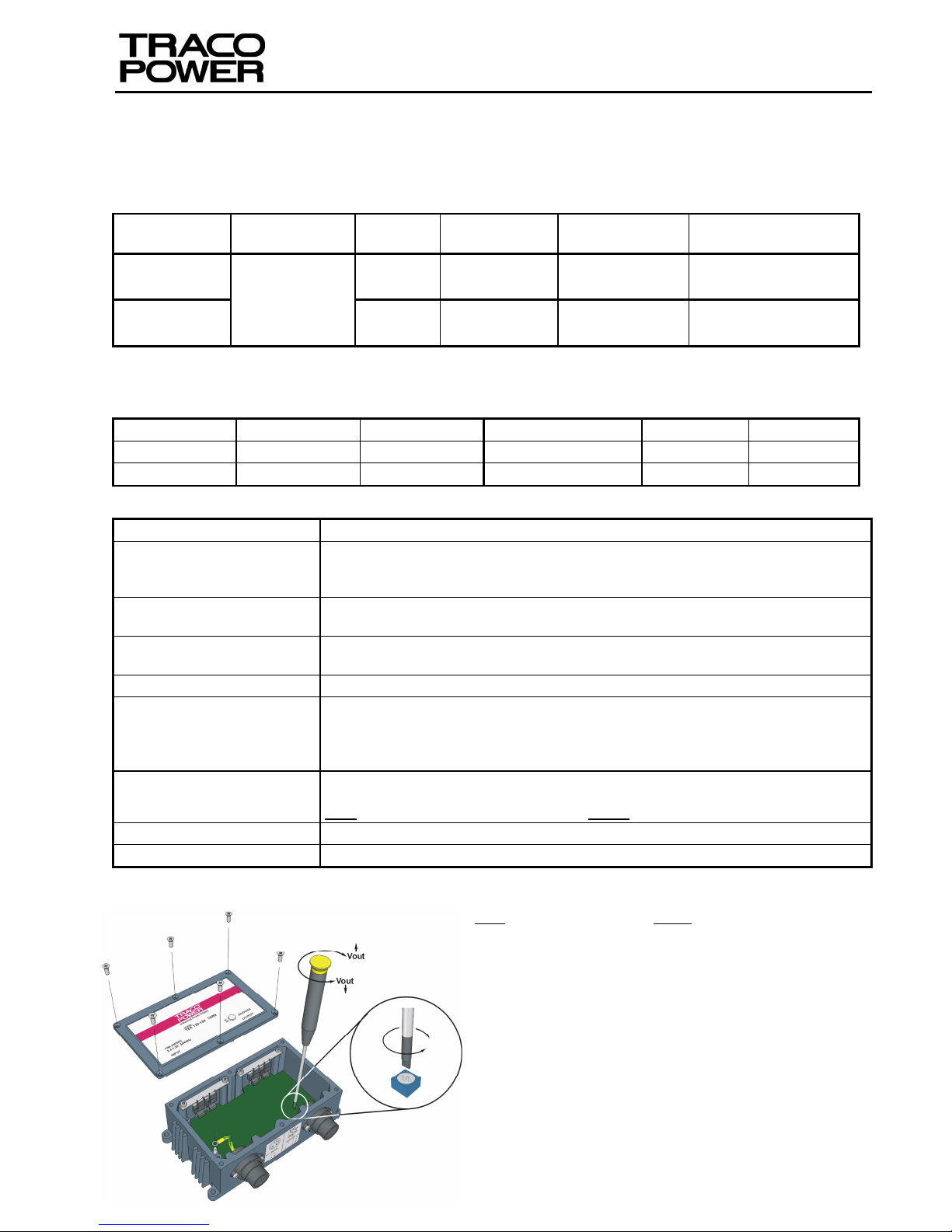
Table 3
Output Voltage adjustment:
Note: The integrity of the seal cannot be guaranteed once the cover
has been removed in the field!
To adjust the output voltage, the case cover must be removed. Carefully loosen
and remove all six screws, then remove the cover. The output voltage of the unit
can be adjusted by turning the potentiometer screw, using an insulated
screwdriver. By turning the screw clockwise (cw) the output voltage will increase;
by turning the screw counter-clockwise (ccw), the output voltage will decrease.
The output voltage level should only be adjusted with the output connected to a
load, (similar to the load used in the application). After adjusting the output
voltage to the required value, the case must be carefully reassembled. Place the
cover over the case and ensure that the rubber-sealing gasket is undamaged,
and is correctly positioned. Secure the lid with the six screws. Tighten the screws
gradually, moving diagonally from one to another. The recommended tightening
torque is 0.6Nm (5.310lb·in).
Operational Input Voltage
AC: 85Vac – 264Vac, 50 / 60Hz. DC: 85Vdc* – 375Vdc (*Observe derating)
Operating temperature range:
Natural Air Convection
Cooling
-40°C – +85°C max (Atex: -40°C - +70°C) (*Observe derating)
-40°F – +185°F max (Atex: -40°F - +158°F) (*Observe derating)
Output Power Derating:
above +60°C 2%/
K
above 140°F 2%/
K
Storage temperature range:
-40°C – +85°C max
-40°F – +185°F max
Parallel Operation:
Only possible with external decoupling diode.
Connectors on the user side:
(see Fig. 2 & Fig. 3)
Input Cable Assembly: See Fig.2 (Tracopower P/N: TEX–IP–ASSY, 3 x 1.3mm²)
Input Connector: Binder Circular Connector Series 693: 99-4222-14-04
Output Cable Assembly: See Fig.3 (Tracopower P/N: TEX–OP–ASSY, 7 x 0.8mm²)
Output Connector: Binder Circular Connector Series 693: 99-4217-160-07
Wiring: Material Copper
Temp: -40°C – +125°C (-40°F – + 257°F)
Input: 3 x 0.8mm2– 2mm2max (AWG 18 – AWG 14) (1 x Live; 1 x Neutral; 1 x Protective Earth)
Output: 7 x 0.8mm2– 1.3mm2max (AWG18–AWG 16) (3 x +V
out
; 3 x –V
out
; 1 x Protective Earth).
Input: TEX-IP-ASSY Cord Diameter = 10 – 12mm / Output:TEX-OP-ASSY Cord Diameter = 12 – 14mm
Case protection:
IP67 (according to IEC 60529), NEMA 6P, UL50 4X
Case material:
Die-Cast Aluminium (chassis and cover)
Fig. 1

http://www.tracopower.com
Rev: 5.6/4915
Safety Instructions:
Before installation read these instructions carefully and
completely. This installation instruction cannot account for
every possible condition of installation, operation or
maintenance. Further information can be obtained from
your local distributor’s office or from the product datasheet,
which can be downloaded, from our website:
http://tracopower.com/products/tex120.pdf.
The mains supply voltage connection, must be in
accordance to IEC 62103, EN 50178 and IEC 60364, VDE
100.
Before any installation, maintenance or modification work
ensure that the main switch is switched off and prevented
from being switched on again. Normally, live components
cannot be touched, but while adjusting the output voltage
live components can be touched. Non-observance,
touching of any live components or improper handling of
this power supply can result in death, severe personal
injury or substantial property damage. Proper and safe
operation is dependent on proper storage, handling,
installation and operation.
Compliance with the relevant national regulations (in the
USA, Europe and other countries) must be ensured.
Before operation is started the following conditions must
be ensured:
Connection to mains supply in compliance with national
regulations (VDE0100 and EN50178).
By use of stranded wires, all strands must be fastened
in the terminal blocks. (Potential danger of contact with
the case)
Power supply and mains wires must be sufficiently
fused.
Degree of protection I to IEC536.The non-fused protec-
tive earth connection must be connected to the FG
terminal (Protection Class I).
All output wires must be rated for the power supply out-
put current and must be connected with the correct
polarity.
Sufficient cooling must be ensured.
Never work on the power supply if power is supplied!
Risk of electric arcs and electrical shock, which can cause
death, severe personal injury or substantial property damage.
Warning: Hazardous voltages and components storing a
very substantial amount of energy are present in this
power supply during normal operating conditions. However,
these are inaccessible. Improper handling may result in an
electric shock or serious burns! Do not open the power
supply until at least 5 minutes after it has been disconnected from the mains on all poles.
Class I Equipment (Chassis earthed)
Do not operate voltage adjustment when an explosive
atmosphere may be present
Do not disconnect while circuit is alive, unless area is
known to be non-hazardous.
Recycling: The unit contains elements that are
suitable for recycling, and components that need
special disposal. You are therefore requested to make
sure that the power supply will be recycled at the end
of its service life.
These power supplies are constructed in accordance with
the safety requirements of EN60079-0:2009 &
EN60079-15:2010, Ex nA IIC T4 Gc.
If the equipment is used in a manner not specified by the
manufacturer, the protection provided by the equipment
may be impaired.
The power input and output cables must NOT touch the
enclosure during operation of the equipment.
Only trained personnel may open the power supply. Once the
cover is opened, the warranty is void!
Do not introduce any objects into the power supply. The output
voltage adjustment potentiometer may only be actuated using
an insulated screwdriver.
Keep away from fire
WARNING: – POTENTIAL ELECTROSTATIC CHARGING HAZARD –
Prevent unintentional contact with a dry cloth.
Do NOT clean surfaces with a dry cloth!
Clean ONLY with a damp cloth.
Installation Instructions:
User-side connector/Cable assemblies shown in Fig. 2 and
Fig. 3 on page 3.
Copper conductors rated min. 60/75C only are to be used.
Wire size 18-14 AWG only are to be used. (See Table 3)
These devices are intended for installation on industrial
machines in accordance with the "Electrical Standard for
Industrial Machinery" (NFPA79). Due to the nature of these
devices they may not be suitable for installation accordance
with the "National Electrical Code" (NFPA70).
The suitability of the use of flexible cord per CEC, PART I,
Rule 4-010, is to be determined by the local inspection
authority having jurisdiction. For Hazard Location, this
device must be installed within a suitable enclosure.
This power supply is designed for professional outdoor
systems as well as indoor systems. It may be installed and
put into service by qualified personnel only.
Do not operate without PE connection! To comply with EMC
and safety standards (CE mark, approvals) the power supply must be operated only if PE terminal is connected to the
non-fused earth conductor.
The correct mounting position for optimal cooling perform-
ance must be observed. Do not cover any ventilation
holes. Leave a free space of minimum 50mm (2in.) above
and below the power supply. Observe power derating.
The internal fuse is not accessible, as the user may not re-
place it. If this internal fuse has blown, the power supply
has an internal defect and, for safety reasons, must be
shipped to the local distributor. In case this internal fuse
has to be replaced in the field, replace only with same type
and rating of fuse for continued protection against risk of
fire.
When no connector is connected to the unit, the connectors
shall be sealed with the cover caps to maintain the degree
of protection.
Cover cap for Input connector 08-2301-000-000
Cover cap for Output connector 08-2302-000-000
 Loading...