

TEP 150-WI Series Application Note
DC/DC Converter 9 to 36Vdc or 18 to 75Vdc Input and 150 Watt Output Power
3.3Vdc to 48 Vdc Single Output
Complete TEP-150WI datasheet can be downloaded at:
http://www .tracopower .com/products/tep150wi.pdf
Pending
Features
• 200 watts maximum output power
• 4:1 wide input range
• High efficien cy up to 88%
• Heat sinks available for extended operati on
temperature
• CV + CC mode
• No minimum load
• Adjustable output voltage
• Under-voltage lockout
• Input reverse protection
• Input to output basic Insulation
• Meet EN55022 class without external filter
• Six-sided metal shielding
• Wall mount application
• RoHS compliant
Options
• Remote on/off logic config uration
Applications
• Wireless Network
• Telecom/ Datacom
• Industry Control System
• Distributed Power Architectures
• Semiconductor Equipment
• Battery Charger
General Description
TEP 150WI series DC/DC converters provide up t o 200 watts of output power . All model features a wi de input range, adjustab le
output voltage and constant current mode ou tput limit. The TEP 150WI Converters are especially suited to telecom, networkin g
and industrial appli cation.
Table of contents
Absolute Maximum Rating P2 Over Temperature Protection P28
Output Specification P2 – P3 Thermal Considerations P28
Input Specification P3 Heat Sink P28
General Specification P4 Remote ON/OFF Control P29
Characteristic Curves P5 – P24 Mechanical Data P30
Testing Configurations P25 Packaging Information P31
Output Voltage Adjustment P26 Order Code P31
Output Over Current Protec tion P27 Safety and Installation Instruction P32
Short Circuitry Protection P27 MTBF and Reliability P32
Output Over Voltage Protection P27
Created by Traco Electronic AG Arp. www.tracopower.com Date: July 28th, 2009 / Rev.: 1.0 / Page 1 / 32

Application Note
150W Single Output
Absolute Maximum Rating
Parameter Device Min Max Unit
Input Voltage
Continuous
Transient (1000mS )
TEP 150-24xxWI
TEP 150-48xxWI
TEP 150-24xxWI
TEP 150-48xxWI
40
80
50
100
Vdc
Vdc
Vdc
Vdc
Operating Ambient Temperature (with de-rating) All -40 85 °C
Storage Temperature All -55 125 °C
I/O Isolation Voltage All 2250
Vdc
Output Specif ication
Parameter Device Min Typ Max Unit
Output Voltage
(V
in
= V
in nom
, I
= I
out
, TA = 25°C)
out max
TEP 150-xx12WI
TEP 150-xx13WI
TEP 150-xx15WI
TEP 150-xx16WI
TEP 150-xx18WI
11.88
14.85
23.76
27.72
47.52
12
15
24
28
48
Voltage Adjustability (see page 26) All 0 +20
Output Regulation
Line (V
in min
to V
at Full Load)
in max
Load (0% to 100% of Full Load)
TEP 150-xx12WI
TEP 150-xx13WI
TEP 150-xx15WI
TEP 150-xx16WI
TEP 150-xx18WI
TEP 150-xx12WI
TEP 150-xx13WI
TEP 150-xx15WI
TEP 150-xx16WI
TEP 150-xx18WI
Output Ripple & Noise
(V
in
= V
in nom
, I
= I
out
, TA = 25°C).
out max
Peak-to-Peak (5Hz to 20MHz bandwidth)
TEP 150-xx12WI
TEP 150-xx13WI
TEP 150-xx15WI
TEP 150-xx16WI
TEP 150-xx18WI
T empe rature Coefficient All -0.02 +0.02 %/°C
Output V oltage Oversho ot
(V
in
= V
in min
to V
in max
; I
= I
out
, TA = 25°C).
out max
Dynamic Load Response
(∆I
/ ∆t = 1A/10µS ; Vin = V
out
; TA = 25°C)
in nom
Load step change between 75% to 100% of I
Peak Deviation
Setting Time (V
< 10% peak deviation) All
out
out max
All 0 5
TEP 150-xx12WI
TEP 150-xx13WI
TEP 150-xx15WI
TEP 150-xx16WI
TEP 150-xx18WI
900
900
1400
1400
1400
200
12.12
15.15
24.24
28.28
48.48
Vdc
Vdc
Vdc
Vdc
Vdc
% V
24
30
48
56
96
48
60
96
1 12
192
mV
mV
mV
mV
mV
mV
mV
mV
mV
mV
100
100
200
200
350
mV
mV
mV
mV
mV
% V
mV
mV
mV
mV
mV
µS
out
pk-pk
pk-pk
pk-pk
pk-pk
pk-pk
out
Created by Traco Electronic AG Arp. www.tracopower.com Date: July 28th, 2009 / Rev.: 1.0 / Page 2 / 32

Application Note
150W Single Output
Output Specif ication (continued)
Parameter Device Min Typ Max Unit
Output Current TEP 150-xx12WI
TEP 150-xx13WI
TEP 150-xx15WI
TEP 150-xx16WI
TEP 150-xx18WI
Output Over V oltage P rotection
(Non-latch Hiccup)
TEP 150-xx12WI
TEP 150-xx13WI
TEP 150-xx15WI
TEP 150-xx16WI
TEP 150-xx18WI
0
0
0
0
0
15.00
18.75
30.00
35.00
60.00
12.5
10.0
6.3
5.4
3.2
16.80
21.00
33.60
39.20
67.20
Output Over Current Protection (CC Mode) All 105 110 120
Input Specification
Parameter Device Min Typ Max Unit
Operating Input Voltage TEP 150-24xxWI
TEP 150-48xxWI
Input Current
(Maximum value at V
= V
in
in nom
, I
= I
out
out max
)
TEP 150-2412WI
TEP 150-2413WI
TEP 150-2415WI
TEP 150-2416WI
TEP 150-2418WI
TEP 150-4812WI
TEP 150-4813WI
TEP 150-4815WI
TEP 150-4816WI
TEP 150-4818WI
Input reflected ripple current (see page 25)
(5 to 20MHz,)
Start Up Time
TEP 150-24xxWI
TEP 150-48xxWI
All
(Vin = Vin(nom) and constant resistive load)
Power up
Remote ON/OFF
Remote ON/OFF (see page 29)
(The On/Off pin voltage is referenced to -V
)
IN
All
Positive logic (Standard): Device code without Suffix
DC-DC ON (Open)
DC-DC OFF (Short)
Negative logic (Option): Device code with Suffix “-N”
DC-DC ON (Short)
DC-DC OFF (Open)
Remote Off Input Current
Input Current of Remote Control Pin
Under Volt age Lockout Turn-on T hreshold TEP 150-24xxWI
TEP 150-48xxWI
Under Volt age Lockout Turn-of f Threshold TEP 150-24xxWI
TEP 150-48xxWI
9
18
24
48
36
75
7.53
7.53
7.50
7.50
7.71
3.72
3.72
3.71
3.71
3.81
100
150
25
25
3
0
0
3
-0.5
3.5
8.8
17.6
8.2
16.2
12
1.2
1.2
12
1.0
A
A
A
A
A
Vdc
Vdc
Vdc
Vdc
Vdc
% I
out
Vdc
Vdc
A
A
A
A
A
A
A
A
A
A
mA
mA
pk-pk
pk-pk
mS
mS
Vdc
Vdc
Vdc
Vdc
mA
mA
Vdc
Vdc
Vdc
Vdc
Created by Traco Electronic AG Arp. www.tracopower.com Date: July 28th, 2009 / Rev.: 1.0 / Page 3 / 32

Application Note
150W Single Output
General Spe cification
Parameter Device Min Typ Max Unit
Efficiency
(V
in
= V
in nom
, I
= I
out
, TA = 25°C)
out max
Isolation voltage (for 60 seconds)
Input to Output
Input to Case
Output to Case
TEP 150-2412WI
TEP 150-2413WI
TEP 150-2415WI
TEP 150-2416WI
TEP 150-2418WI
TEP 150-4812WI
TEP 150-4813WI
TEP 150-4815WI
TEP 150-4816WI
TEP 150-4818WI
All
86
86
87
87
86
87
87
88
88
87
2250
1600
1600
Isolation resistance All 1 GΩ
Isolation capacitan ce All 3500 pF
TEP 150-xx12WI
Switching Frequency
TEP 150-xx13WI
TEP 150-xx15WI
300
TEP 150-xx16WI
TEP 150-xx18WI 275
Weight TEP 150-xxxxWI 225 g
MTBF
Bellcore TR-NWT-000332, T
MIL-HDBK-217F
= 40°C,
C
All
1’525’000
135’300
Over Temperature Protection (see page 28) All 110 °C
%
%
%
%
%
%
%
%
%
%
Vdc
Vdc
Vdc
KHz
hours
hours
Created by Traco Electronic AG Arp. www.tracopower.com Date: July 28th, 2009 / Rev.: 1.0 / Page 4 / 32
Application Note
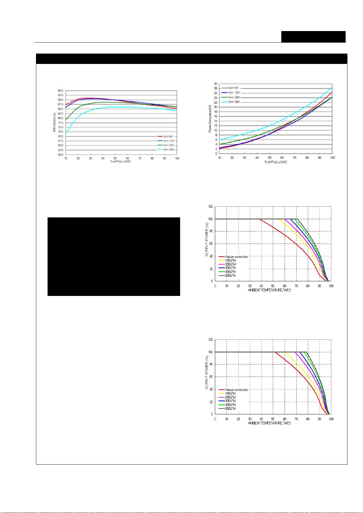
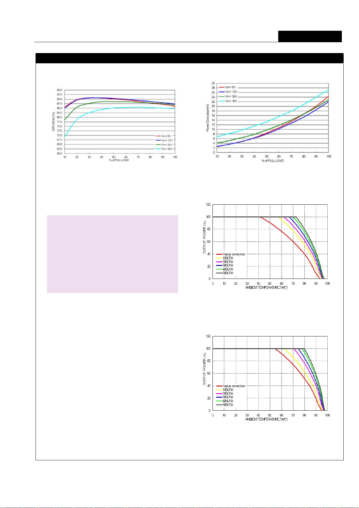
Characteristic Curves
All test conditions are at 25°C. The figures are identical for TEP 150-2412WI
150W Single Output
Efficiency versus Output Current Power Dissipation versus Output Cu rrent
Efficiency versus Input Voltage. Full Load Derating Output Current versus Ambient Temperature
with iron Base plate and Airflow , V
in
= V
in nom
(The base-plate dimension i s 19” * 3.5” * 0.6 3”.
The height is EIA standard 2U.)
Derating Output Current Versus Ambient Temperature
with iron Base plate , Heat-Sink and Airflow , V
in
= V
in nom
(The base-plate dimension i s 19” * 3.5” * 0.6 3”.
The height is EIA standard 2U.)
Created by Traco Electronic AG Arp. www.tracopower.com Date: July 28th, 2009 / Rev.: 1.0 / Page 5 / 32
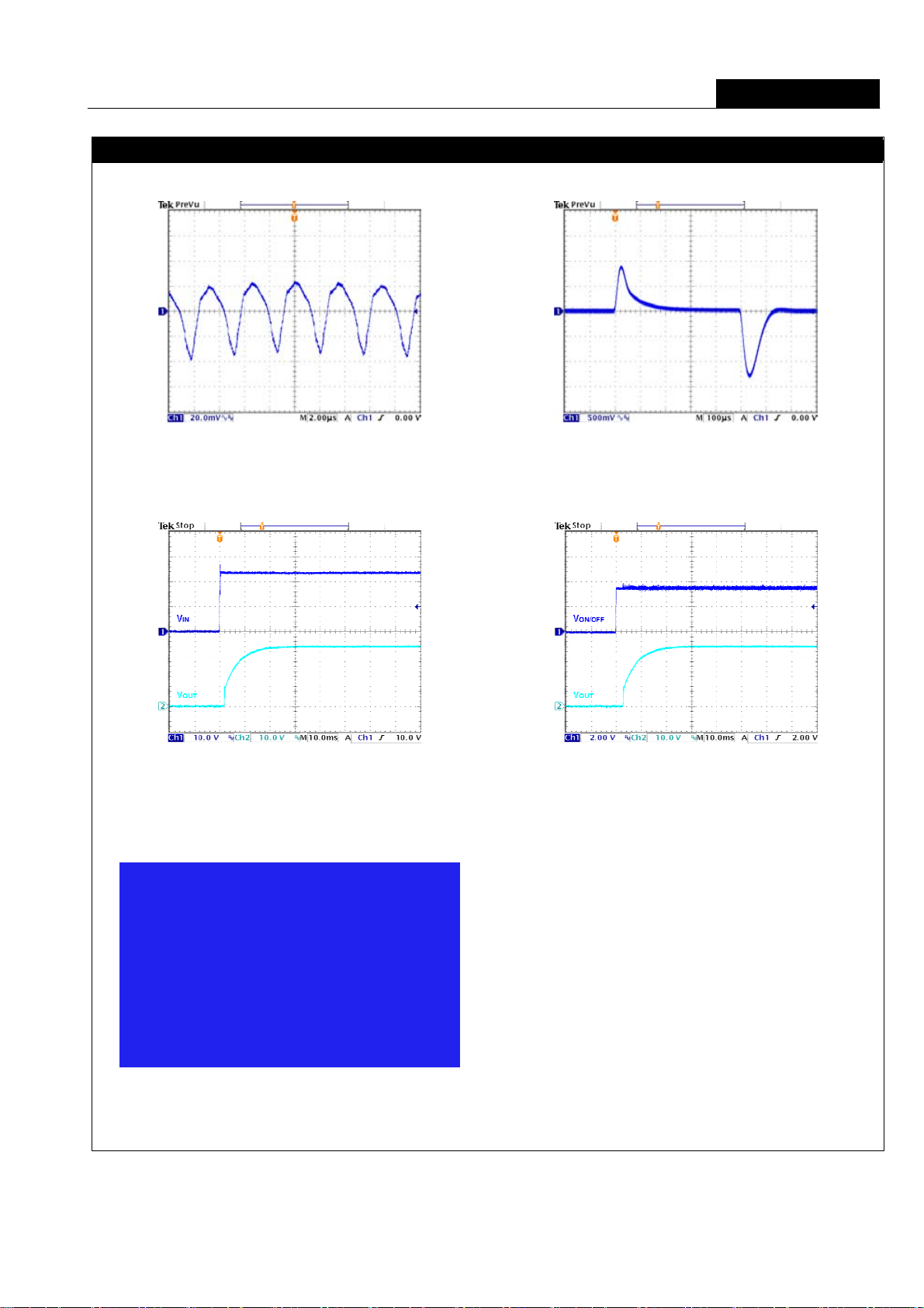
Application Note
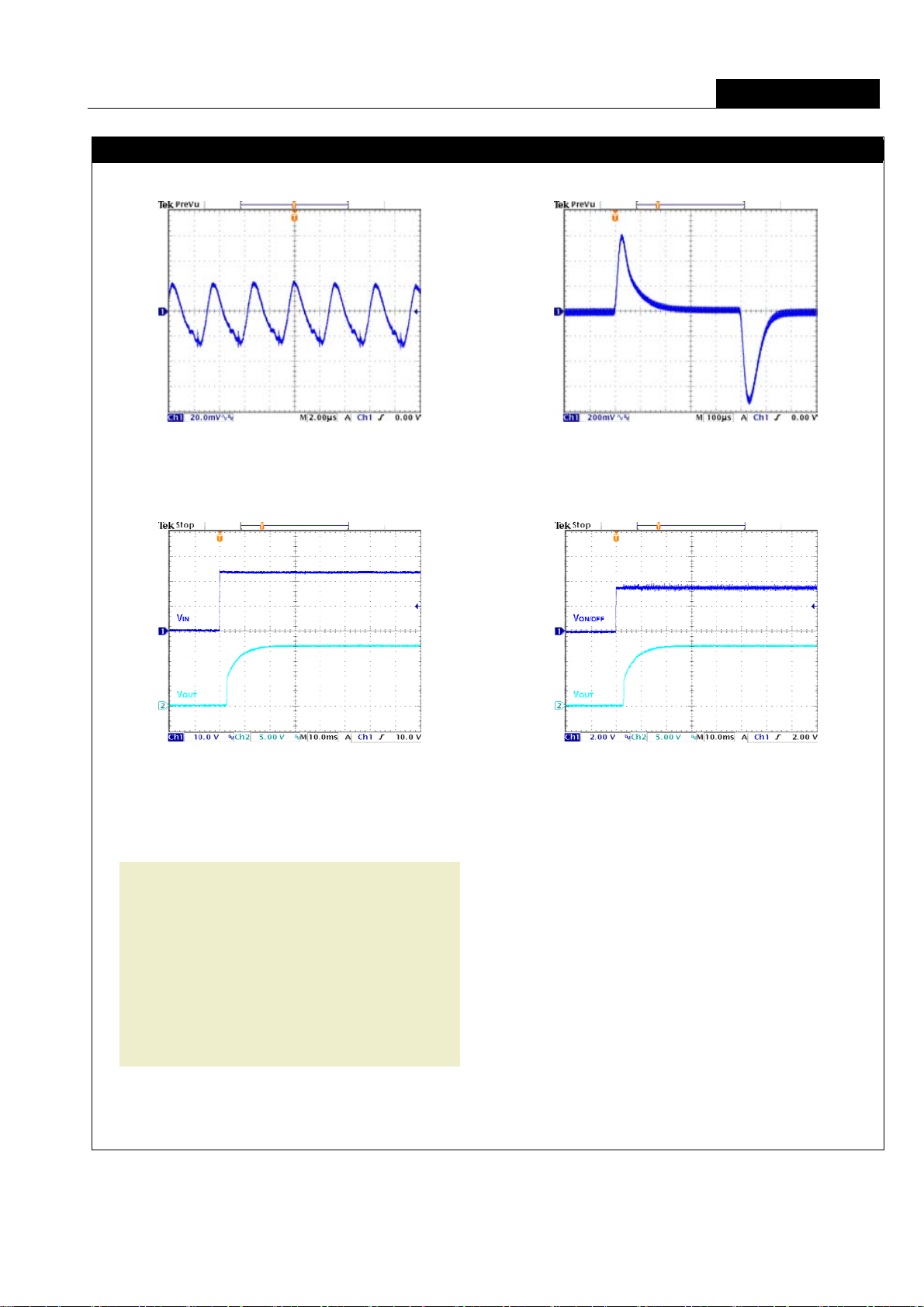
Characteristic Curves (Continued)
All test conditions are at 25°C. The figures are identical for TEEP 150-2412WI
Typical Output Ripple and Noise.
V
in
= V
, Full Load
in nom
Transient Response to Dynamic Load Change from
100% to 75% to 100% of Full Load ; Vin = V
150W Single Output
in nom
Typica l Input St art-Up and Output Rise Characteri stic
V
in
= V
, Full Load
in nom
Conduction Emission of EN55022 Class A
V
in
= V
, Full Load
in nom
Using ON/OFF Voltage S tart-Up and V
V
= V
in
, Full Load
in nom
Rise Characteristic
out
Created by Traco Electronic AG Arp. www.tracopower.com Date: July 28th, 2009 / Rev.: 1.0 / Page 6 / 32

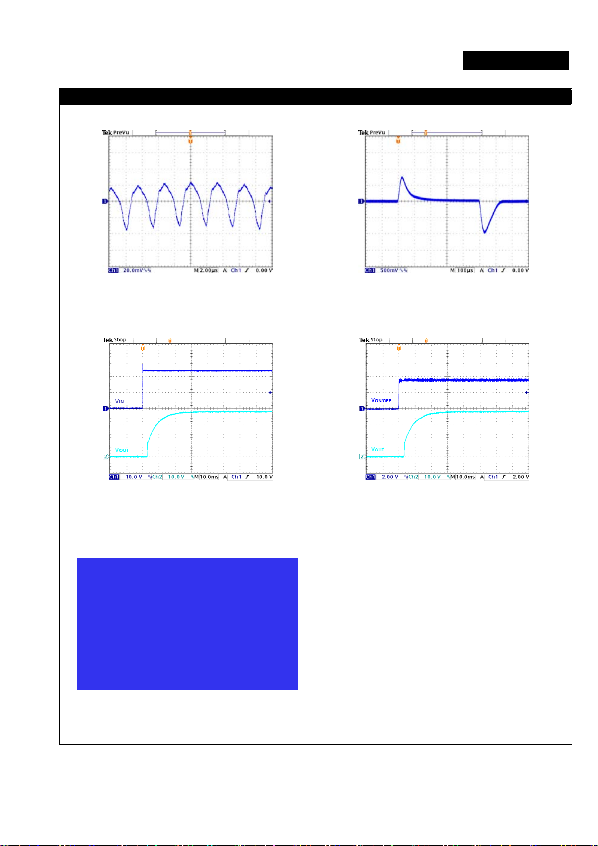
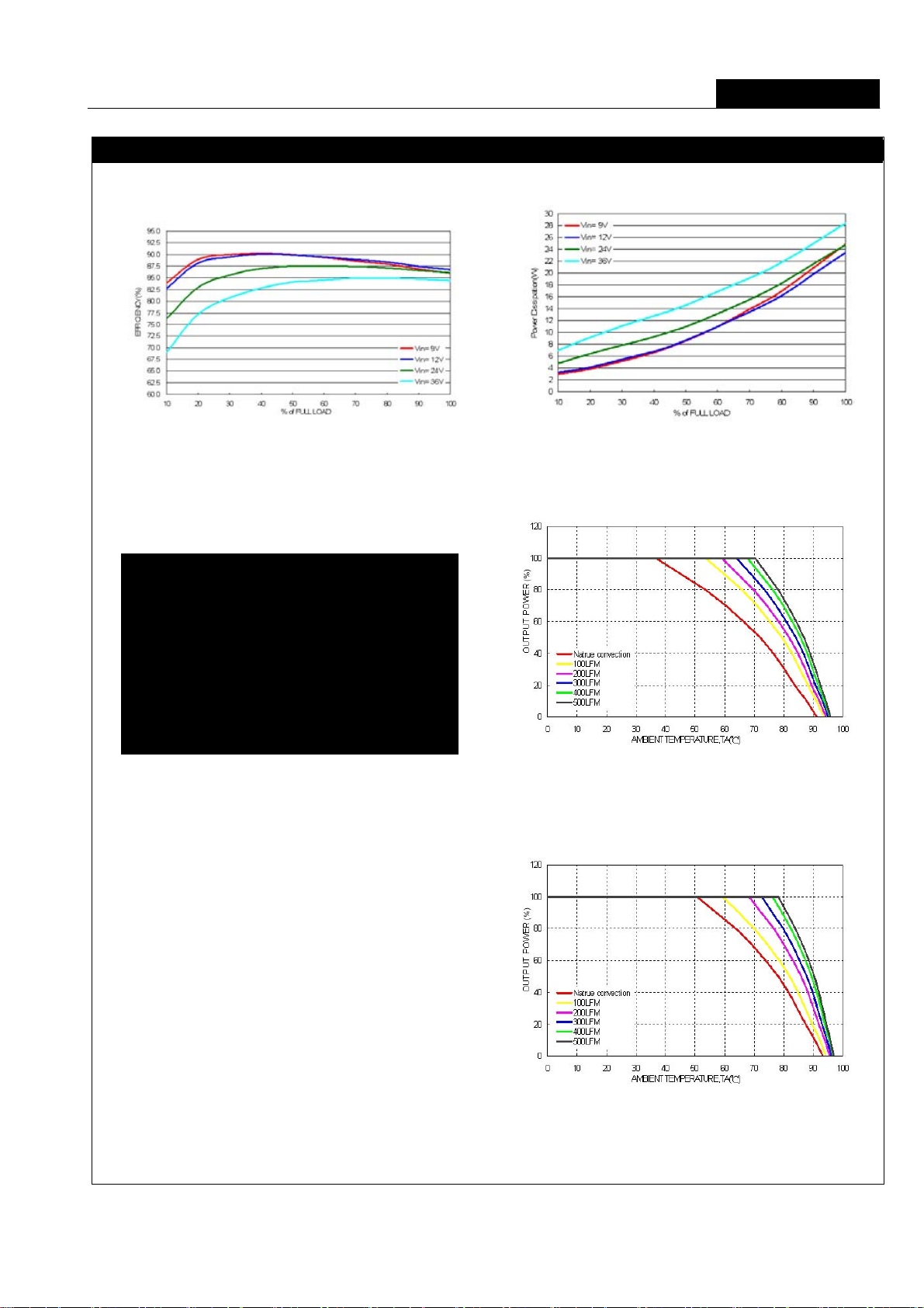
Application Note
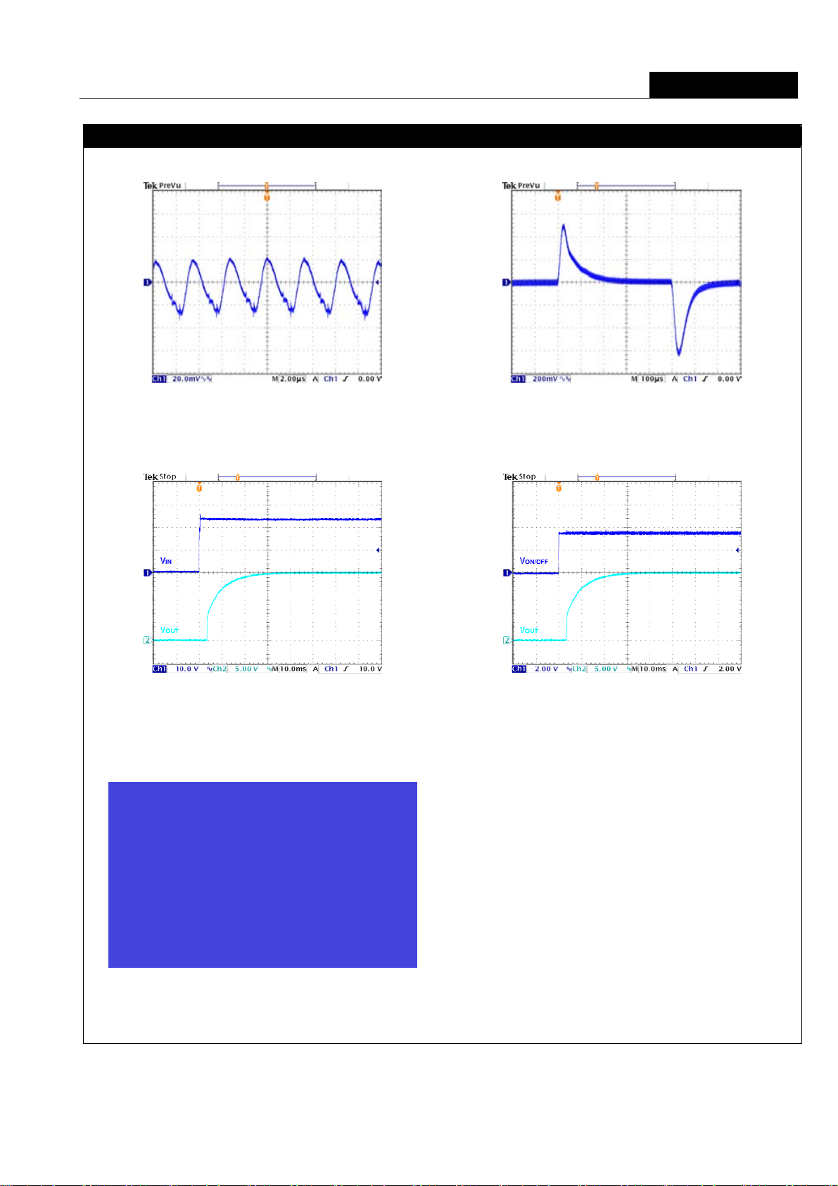
Characteristic Curves (Continued)
All test conditions are at 25°C. The figures are identical for TEP 150-2413WI
150W Single Output
Efficiency versus Output Current Power Dissipation versus Output Cu rrent
Efficiency versus Input Voltage. Full Load Derating Output Current versus Ambient Temperature
with iron Base plate and Airflow , V
in
= V
in nom
(The base-plate dimension i s 19” * 3.5” * 0.6 3”.
The height is EIA standard 2U.)
Derating Output Current Versus Ambient Temperature
with iron Base plate , Heat-Sink and Airflow , V
in
= V
in nom
(The base-plate dimension i s 19” * 3.5” * 0.6 3”.
The height is EIA standard 2U.)
Created by Traco Electronic AG Arp. www.tracopower.com Date: July 28th, 2009 / Rev.: 1.0 / Page 7 / 32
Application Note
Characteristic Curves (Continued)
All test conditions are at 25°C. The figures are identical for TEP 150-2413WI
Typical Output Ripple and Noise.
V
in
= V
, Full Load
in nom
Transient Response to Dynamic Load Change from
150W Single Output
100% to 75% to 100% of Full Load ; Vin = V
in nom
Typica l Input St art-Up and Output Rise Characteri stic
V
in
= V
, Full Load
in nom
Conduction Emission of EN55022 Class A
V
in
= V
, Full Load
in nom
Using ON/OFF Voltage S tart-Up and V
V
= V
in
, Full Load
in nom
Rise Characteristic
out
Created by Traco Electronic AG Arp. www.tracopower.com Date: July 28th, 2009 / Rev.: 1.0 / Page 8 / 32
Application Note
Characteristic Curves (Continued)
All test conditions are at 25°C. The figures are identical for TEP 150-2415WI
150W Single Output
Efficiency versus Output Current Power Dissipation versus Output Cu rrent
Efficiency versus Input Voltage. Full Load Derating Output Current versus Ambient Temperature
with iron Base plate and Airflow , V
in
= V
in nom
(The base-plate dimension i s 19” * 3.5” * 0.6 3”.
The height is EIA standard 2U.)
in nom
Derating Output Current Versus Ambient Temperature
with iron Base plate , Heat-Sink and Airflow , V
in
= V
(The base-plate dimension i s 19” * 3.5” * 0.6 3”.
The height is EIA standard 2U.)
Created by Traco Electronic AG Arp. www.tracopower.com Date: July 28th, 2009 / Rev.: 1.0 / Page 9 / 32
Application Note
Characteristic Curves (Continued)
All test conditions are at 25°C. The figures are identical for TEP 150-2415WI
Typical Output Ripple and Noise.
V
in
= V
, Full Load
in nom
Transient Response to Dynamic Load Change from
150W Single Output
100% to 75% to 100% of Full Load ; Vin = V
in nom
Typica l Input St art-Up and Output Rise Characteri stic
V
in
= V
, Full Load
in nom
Conduction Emission of EN55022 Class A
V
in
= V
, Full Load
in nom
Using ON/OFF Voltage S tart-Up and V
V
= V
in
, Full Load
in nom
Rise Characteristic
out
Created by Traco Electronic AG Arp. www.tracopower.com Date: July 28th, 2009 / Rev.: 1.0 / Page 10 / 32

Application Note
Characteristic Curves (Continued)
All test conditions are at 25°C. The figures are identical for TEP 150-2416WI
150W Single Output
Efficiency versus Output Current Power Dissipation versus Output Cu rrent
Efficiency versus Input Voltage. Full Load Derating Output Current versus Ambient Temperature
with iron Base plate and Airflow , V
in
= V
in nom
(The base-plate dimension i s 19” * 3.5” * 0.6 3”.
The height is EIA standard 2U.)
in nom
Derating Output Current Versus Ambient Temperature
with iron Base plate , Heat-Sink and Airflow , V
in
= V
(The base-plate dimension i s 19” * 3.5” * 0.6 3”.
The height is EIA standard 2U.)
Created by Traco Electronic AG Arp. www.tracopower.com Date: July 28th, 2009 / Rev.: 1.0 / Page 11 / 32
Application Note
Characteristic Curves (Continued)
All test conditions are at 25°C. The figures are identical for TEP 150-2416WI
Typical Output Ripple and Noise.
V
in
= V
, Full Load
in nom
Transient Response to Dynamic Load Change from
150W Single Output
100% to 75% to 100% of Full Load ; Vin = V
in nom
Typica l Input St art-Up and Output Rise Characteri stic
V
in
= V
, Full Load
in nom
Conduction Emission of EN55022 Class A
V
in
= V
, Full Load
in nom
Using ON/OFF Voltage S tart-Up and V
V
= V
in
, Full Load
in nom
Rise Characteristic
out
Created by Traco Electronic AG Arp. www.tracopower.com Date: July 28th, 2009 / Rev.: 1.0 / Page 12 / 32
Application Note
Characteristic Curves (Continued)
All test conditions are at 25°C. The figures are identical for TEP 150-2418WI
150W Single Output
Efficiency versus Output Current Power Dissipation versus Output Cu rrent
Efficiency versus Input Voltage. Full Load Derating Output Current versus Ambient Temperature
with iron Base plate and Airflow , V
in
= V
in nom
(The base-plate dimension i s 19” * 3.5” * 0.6 3”.
The height is EIA standard 2U.)
in nom
Derating Output Current Versus Ambient Temperature
with iron Base plate , Heat-Sink and Airflow , V
in
= V
(The base-plate dimension i s 19” * 3.5” * 0.6 3”.
The height is EIA standard 2U.)
Created by Traco Electronic AG Arp. www.tracopower.com Date: July 28th, 2009 / Rev.: 1.0 / Page 13 / 32

Application Note
Characteristic Curves (Continued)
All test conditions are at 25°C. The figures are identical for TEP 150-2418WI
Typical Output Ripple and Noise.
V
in
= V
, Full Load
in nom
Transient Response to Dynamic Load Change from
150W Single Output
100% to 75% to 100% of Full Load ; Vin = V
in nom
Typica l Input St art-Up and Output Rise Characteri stic
V
in
= V
, Full Load
in nom
Conduction Emission of EN55022 Class A
V
in
= V
, Full Load
in nom
Using ON/OFF Voltage S tart-Up and V
V
= V
in
, Full Load
in nom
Rise Characteristic
out
Created by Traco Electronic AG Arp. www.tracopower.com Date: July 28th, 2009 / Rev.: 1.0 / Page 14 / 32

Application Note
Characteristic Curves (Continued)
All test conditions are at 25°C. The figures are identical for TEP 150-4812WI
150W Single Output
Efficiency versus Output Current Power Dissipation versus Output Cu rrent
Efficiency versus Input Voltage. Full Load Derating Output Current versus Ambient Temperature
with iron Base plate and Airflow , V
in
= V
in nom
(The base-plate dimension i s 19” * 3.5” * 0.6 3”.
The height is EIA standard 2U.)
in nom
Derating Output Current Versus Ambient Temperature
with iron Base plate , Heat-Sink and Airflow , V
in
= V
(The base-plate dimension i s 19” * 3.5” * 0.6 3”.
The height is EIA standard 2U.)
Created by Traco Electronic AG Arp. www.tracopower.com Date: July 28th, 2009 / Rev.: 1.0 / Page 15 / 32

Application Note
Characteristic Curves (Continued)
All test conditions are at 25°C. The figures are identical for TEP 150-4812WI
Typical Output Ripple and Noise.
V
in
= V
, Full Load
in nom
Transient Response to Dynamic Load Change from
150W Single Output
100% to 75% to 100% of Full Load ; Vin = V
in nom
Typica l Input St art-Up and Output Rise Characteri stic
V
in
= V
, Full Load
in nom
Conduction Emission of EN55022 Class A
V
in
= V
, Full Load
in nom
Using ON/OFF Voltage S tart-Up and V
V
= V
in
, Full Load
in nom
Rise Characteristic
out
Created by Traco Electronic AG Arp. www.tracopower.com Date: July 28th, 2009 / Rev.: 1.0 / Page 16 / 32

Application Note
Characteristic Curves (Continued)
All test conditions are at 25°C. The figures are identical for TEP 150-4813WI
150W Single Output
Efficiency versus Output Current Power Dissipation versus Output Cu rrent
Efficiency versus Input Voltage. Full Load Derating Output Current versus Ambient Temperature
with iron Base plate and Airflow , V
in
= V
in nom
(The base-plate dimension i s 19” * 3.5” * 0.6 3”.
The height is EIA standard 2U.)
in nom
Derating Output Current Versus Ambient Temperature
with iron Base plate , Heat-Sink and Airflow , V
in
= V
(The base-plate dimension i s 19” * 3.5” * 0.6 3”.
The height is EIA standard 2U.)
Created by Traco Electronic AG Arp. www.tracopower.com Date: July 28th, 2009 / Rev.: 1.0 / Page 17 / 32

Application Note
Characteristic Curves (Continued)
All test conditions are at 25°C. The figures are identical for TEP 150-4813WI
Typical Output Ripple and Noise.
V
in
= V
, Full Load
in nom
Transient Response to Dynamic Load Change from
150W Single Output
100% to 75% to 100% of Full Load ; Vin = V
in nom
Typica l Input St art-Up and Output Rise Characteri stic
V
in
= V
, Full Load
in nom
Conduction Emission of EN55022 Class A
V
in
= V
, Full Load
in nom
Using ON/OFF Voltage S tart-Up and V
V
= V
in
, Full Load
in nom
Rise Characteristic
out
Created by Traco Electronic AG Arp. www.tracopower.com Date: July 28th, 2009 / Rev.: 1.0 / Page 18 / 32

Application Note
Characteristic Curves (Continued)
All test conditions are at 25°C. The figures are identical for TEP 150-4815WI
150W Single Output
Efficiency versus Output Current Power Dissipation versus Output Cu rrent
Efficiency versus Input Voltage. Full Load Derating Output Current versus Ambient Temperature
with iron Base plate and Airflow , V
in
= V
in nom
(The base-plate dimension i s 19” * 3.5” * 0.6 3”.
The height is EIA standard 2U.)
in nom
Derating Output Current Versus Ambient Temperature
with iron Base plate , Heat-Sink and Airflow , V
in
= V
(The base-plate dimension i s 19” * 3.5” * 0.6 3”.
The height is EIA standard 2U.)
Created by Traco Electronic AG Arp. www.tracopower.com Date: July 28th, 2009 / Rev.: 1.0 / Page 19 / 32

Application Note
Characteristic Curves (Continued)
All test conditions are at 25°C. The figures are identical for TEP 150-4815WI
Typical Output Ripple and Noise.
V
in
= V
, Full Load
in nom
Transient Response to Dynamic Load Change from
150W Single Output
100% to 75% to 100% of Full Load ; Vin = V
in nom
Typica l Input St art-Up and Output Rise Characteri stic
V
in
= V
, Full Load
in nom
Conduction Emission of EN55022 Class A
V
in
= V
, Full Load
in nom
Using ON/OFF Voltage S tart-Up and V
V
= V
in
, Full Load
in nom
Rise Characteristic
out
Created by Traco Electronic AG Arp. www.tracopower.com Date: July 28th, 2009 / Rev.: 1.0 / Page 20 / 32

Application Note
Characteristic Curves (Continued)
All test conditions are at 25°C. The figures are identical for TEP 150-4816WI
150W Single Output
Efficiency versus Output Current Power Dissipation versus Output Cu rrent
Efficiency versus Input Voltage. Full Load Derating Output Current versus Ambient Temperature
with iron Base plate and Airflow , V
in
= V
in nom
(The base-plate dimension i s 19” * 3.5” * 0.6 3”.
The height is EIA standard 2U.)
in nom
Derating Output Current Versus Ambient Temperature
with iron Base plate , Heat-Sink and Airflow , V
in
= V
(The base-plate dimension i s 19” * 3.5” * 0.6 3”.
The height is EIA standard 2U.)
Created by Traco Electronic AG Arp. www.tracopower.com Date: July 28th, 2009 / Rev.: 1.0 / Page 21 / 32

Application Note
Characteristic Curves (Continued)
All test conditions are at 25°C. The figures are identical for TEP 150-4816WI
Typical Output Ripple and Noise.
V
in
= V
, Full Load
in nom
Transient Response to Dynamic Load Change from
150W Single Output
100% to 75% to 100% of Full Load ; Vin = V
in nom
Typica l Input St art-Up and Output Rise Characteri stic
V
in
= V
, Full Load
in nom
Conduction Emission of EN55022 Class A
V
in
= V
, Full Load
in nom
Using ON/OFF Voltage S tart-Up and V
V
= V
in
, Full Load
in nom
Rise Characteristic
out
Created by Traco Electronic AG Arp. www.tracopower.com Date: July 28th, 2009 / Rev.: 1.0 / Page 22 / 32

Application Note
Characteristic Curves (Continued)
All test conditions are at 25°C. The figures are identical for TEP 150-4818WI
150W Single Output
Efficiency versus Output Current Power Dissipation versus Output Cu rrent
Efficiency versus Input Voltage. Full Load Derating Output Current versus Ambient Temperature
with iron Base plate and Airflow , V
in
= V
in nom
(The base-plate dimension i s 19” * 3.5” * 0.6 3”.
The height is EIA standard 2U.)
in nom
Derating Output Current Versus Ambient Temperature
with iron Base plate , Heat-Sink and Airflow , V
in
= V
(The base-plate dimension i s 19” * 3.5” * 0.6 3”.
The height is EIA standard 2U.)
Created by Traco Electronic AG Arp. www.tracopower.com Date: July 28th, 2009 / Rev.: 1.0 / Page 23 / 32

Application Note
Characteristic Curves (Continued)
All test conditions are at 25°C. The figures are identical for TEP 150-4818WI
Typical Output Ripple and Noise.
V
in
= V
, Full Load
in nom
Transient Response to Dynamic Load Change from
150W Single Output
100% to 75% to 100% of Full Load ; Vin = V
in nom
Typica l Input St art-Up and Output Rise Characteri stic
V
in
= V
, Full Load
in nom
Conduction Emission of EN55022 Class A
V
in
= V
, Full Load
in nom
Using ON/OFF Voltage S tart-Up and V
V
= V
in
, Full Load
in nom
Rise Characteristic
out
Created by Traco Electronic AG Arp. www.tracopower.com Date: July 28th, 2009 / Rev.: 1.0 / Page 24 / 32

Application Note
T esti ng Configurations
Input reflected-ripple current measurement test up
Note: TEP 150WI series test Input reflected-ripple current measurement without external filter.
Peak-to-peak output ripple & noi se measurement test up
150W Single Output
Output voltage and efficiency measur ement test up
Note: All mea surements are ta ken at the module terminals.
Efficiency
=
IV
×
OUTOUT
%100×
IV
×
ININ
Created by Traco Electronic AG Arp. www.tracopower.com Date: July 28th, 2009 / Rev.: 1.0 / Page 25 / 32

Application Note
150W Single Output
Output V oltage Adjustment
The output voltage is adju stable from 0% to +20% trim up of nomina l output voltage by connecting an exte rnal resistor bet ween
the TRIM1 and TRIM2 pins. With an external resistor between the TRIM1 and TRIM2 pins, the output voltage set point
increases. The maximum output deviation is +20%. The value of external resistor can be obtained by trim table shown in next
page.
TRIM TABLE
TEP 150-xx12WI
Trim up (% ) 1 2 3 4 5 6 7 8 9 10
V
(Volts) = 12.12 12.24 12.36 12.48 12.6 12.72 12.84 12.96 13.08 13.2
OUT
RU (KΩ) =
Trim up (% ) 11 12 13 14 15 16 17 18 19 20
V
(Volt s) = 13.32 13.44 13.56 13.68 13.8 13.92 14.04 14.16 14.28 14.4
OUT
RU (KΩ) =
TEP 150-xx13WI
Trim up (% ) 1 2 3 4 5 6 7 8 9 10
V
(Volts) = 15.15 15.3 15.45 15.6 15.75 15.9 16.05 16.2 16.35 16.5
OUT
RU (KΩ) =
Trim up (% ) 11 12 13 14 15 16 17 18 19 20
V
(Volt s) = 16.65 16.8 16.95 17.1 17.25 17.4 17.55 17.7 17.85 18
OUT
RU (KΩ) =
TEP 150-xx15WI
Trim up (% ) 1 2 3 4 5 6 7 8 9 10
V
(Volts) = 24.24 24.48 24.72 24.96 25.2 25.44 25.68 25.92 26.16 26.4
OUT
RU (KΩ) =
Trim up (% ) 11 12 13 14 15 16 17 18 19 20
V
(Volt s) = 26.64 26.88 27.12 27.36 27.6 27.84 28.08 28.32 28.56 28.8
OUT
RU (KΩ) =
TEP 150-xx16WI
Trim up (% ) 1 2 3 4 5 6 7 8 9 10
V
(Volts) = 28.28 28.56 28.84 29.12 29.4 29.68 29.96 30.24 30.52 30.8
OUT
RU (KΩ) =
Trim up (% ) 11 12 13 14 15 16 17 18 19 20
V
(Volt s) = 31.08 31.36 31.64 31.92 32.2 32.48 32.76 33.04 33.32 33.6
OUT
RU (KΩ) =
TEP 150-xx18WI
Trim up (% ) 1 2 3 4 5 6 7 8 9 10
V
(Volts) = 48.48 48.96 49.44 49.92 50.4 50.88 51.36 51.84 52.32 52.8
OUT
RU (KΩ) =
Trim up (% ) 11 12 13 14 15 16 17 18 19 20
V
(Volt s) = 53.28 53.76 54.24 54.72 55.2 55.68 56.16 56.64 57.12 57.6
OUT
Created by Traco Electronic AG Arp. www.tracopower.com Date: July 28th, 2009 / Rev.: 1.0 / Page 26 / 32
RU (KΩ) =
222.64 105.09 66.35 47.06 35.51 27.83 22.34 18.23 15.03 12.48
10.39 8.65 7.18 5.91 4.82 3.86 3.02 2.27 1.60 0.99
238.62 113.62 71.95 51.12 38.62 30.29 24.33 19.87 16.40 13.62
11.35 9.45 7.85 6.48 5.29 4.25 3.33 2.51 1.78 1.12
212.47 106.69 68.79 49.30 37.43 29.44 23.70 19.37 15.99 13.28
11.06 9.20 7.63 6.28 5.11 4.08 3.18 2.37 1.65 1.00
255.65 121.72 77.08 54.76 41.36 32.44 26.06 21.28 17.56 14.58
12.14 10.11 8.40 6.93 5.65 4.53 3.55 2.67 1.89 1.19
268.86 127.44 80.57 57.19 43.17 33.84 27.17 22.18 18.29 15.18
12.64 10.52 8.73 7.20 5.87 4.70 3.67 2.76 1.94 1.21

Application Note
150W Single Output
Output Over Current Protection
TEP 150WI series employ a fixed current limit to prevent damage to components within the converters, and will also protect the
load provided that the current limiting crossov er point is set at a current value that the load can handle without damag e.
Normally, the current limit is maintained at approximately 105~120 percent of rated current for TEP 150WI series. If the output
load current is over rating, the output current will keep in a constant value. And the output volt age will fall.
All of the TEP 150WI series current limiting supplies are self restoring; that is, when the overload is removed or corrected, the
output voltage is automati cally restored to the previously set value.
Otherwise, if the output resistance is become short, it will operate in hiccup protection. The details are shown below.
TEP 150-2412WI
TEP 150-4812WI
Vout & Iout Curve
TEP 150-2413WI
TEP 150-4813WI
Vout & Iout Curve
TEP 150-2415WI
TEP 150-4815WI
Vout & Iout Curve
TEP 150-2416WI
TEP 150-4816WI
Vout & Iout Curve
TEP 150-2418WI
TEP 150-4818WI
Vout & Iout Curve
Notes:
CV Region: In normal operation. The output current in spec.
Condition: Resistance Load > Vout / Iout (CC Point)
CC Region: If the output load current i s ov er rating, the output current will keep in a const ant value. And the output volt age
will fall.
Condition: Resistance Load < Vout / Iout (CC Point)
Hiccup Protection: If t he output resist ance is become short. It will operate in hiccup p rotection.
Condition: Vout < 4.3V (typ.) to Output Short. (TEP 150-xx12WI, TEP 150-xx13WI)
Vout < 8.0V (ty p.) to Output Short. (TEP 150-xx15WI, TEP 150-xx16WI)
Vout < 13V (typ.) to Output S hort. (TEP 150-xx18 WI)
Short Circuitry Protection
Continuous, hiccup and auto-recovery mode.
During short circuit, converter still shut d own . The average current during this con ditio n will be very low and the device can be
safety in this condition.
Output Over V oltage Prote ction
The output over-voltage protection consists of circuitry that monitors the voltage on the output terminals. If the voltage on the
output terminals exceeds the over-voltage protection threshold, then the module enter the non-latch hiccup mode.
Created by Traco Electronic AG Arp. www.tracopower.com Date: July 28th, 2009 / Rev.: 1.0 / Page 27 / 32

Application Note
150W Single Output
Over T emperatur e Protection
Sufficient cooling is needed for the power module and provides more reliable operation of the unit. If a fault condition occurs, the
temperature of the unit will be higher. And it will damage the unit. For protecting the power module, the unit includes
over-temperature protection circuit. When the temperature of the case is to the protection threshold, the unit enters “Shunt
Down” mode. And it will auto restart when the temp erature is down.
Thermal Consideration
The power module operates in a variety of thermal environments. However, sufficient cooling should be provided to help ensure
reliable operation of the unit. Heat is removed by conduction, convection, and radiation to the surrounding Environment. Proper
cooling can be verified by measuring the point as the figur e below. The temperature at this location sho uld not exceed 110°C.
When Operating, adequate cooling must be provided to maintain the test point temperature at or below 110°C. Although the
maximum point temperature of the power modules is 110°C, you can limit this temperature to a lower val ue for extremely high
reliability.
TEP 150WI
BOTTOM VIEW
Measurement shown in inches (mm)
Heatsink
The equipped heatsink is for lower temperat ure and higher reliability of the module.
unit: inch (mm)
Created by Traco Electronic AG Arp. www.tracopower.com Date: July 28th, 2009 / Rev.: 1.0 / Page 28 / 32

Application Note
150W Single Output
Remote ON/OFF Control
The Remote ON/OFF Pin is controll ed DC/DC power mo dule to turn on and of f; the user must u se a switch to control the logic
voltage high or low level of the pin referenc ed to –V
switch must be capable of sinking u p to 1 mA at lo w-level logic V oltage. High -level logic of the ON/OFF sign al maximum voltage
is allowable leakage current of the switch at 12V is 0.5 mA.
Remote ON/OFF Implementation Circuits
. The switch can be open collector transistor, FET and Photo-Couple. The
in
Isolated-Closure Remote ON/OFF Level Control Using TTL Out put
Level Control Using Line V oltage
There are two remote con trol options avail able, positive logic and n egative logic.
a. The Positive lo gic structure turned on of the DC/DC mo dule when the ON/OFF pin is at high-l evel logic and low-level lo gic is
turned off it.
When TEP 150WI module is turn ed off at Low-level logic When TEP 150WI module is turned on at High-level logi c
b. The Negat ive logic structu re turned on of the DC/DC mo dule when the ON/OFF pi n is at low-level logi c and turned of f when
at high-level logic.
When TEP 150WI module is turn ed on at Low-level logic When TEP 150WI module is turned off at High-lev el logic
Created by Traco Electronic AG Arp. www.tracopower.com Date: July 28th, 2009 / Rev.: 1.0 / Page 29 / 32

Application Note
150W Single Output
Mechanical Data
TEP 150WI DIMENSIONS
PIN Define Wire Range
1 +Vin (VCC) 14 AWG to 16 A WG
2 +Vin (VCC) 14 AWG to 16 A WG
3 –Vin (GND) 14 A WG to 16 AWG
4 –Vin (GND) 14 A WG to 16 AWG
5 Remote on/off 14 A WG to 24 AWG
6 +V
7 –V
PIN CONNECTION
14 AWG to 16 AWG
out
14 AWG to 16 AWG
out
PRODUCT OPTIONS TABLE
Option Suffix
Positive remote ON/OFF logic Negative remote ON/OFF logic -N
Example:
TEP 150-4812WI
TEP 150-4812WI-N
8 TRIM1 14 AWG to 24 AWG
9 TRIM2 14 AWG to 24 AWG
Created by Traco Electronic AG Arp. www.tracopower.com Date: July 28th, 2009 / Rev.: 1.0 / Page 30 / 32

Application Note
(
3
150W Single Output
Packaging Information
Dimensions shown in millimeters
Order Code
Output Current Input Current Model
Max. Load No Load
Number
Input
Range
Output
Voltage
TEP 150-2412WI 9 – 36Vdc 12Vdc 12.5 A 70mA 7.53A 86
TEP 150-2413WI 9 – 36Vdc 15Vdc 10.0 A 80mA 7.53 A 86
TEP 150-2415WI 9 – 36Vdc 24Vdc 6.3 A 95mA 7.50A 87
TEP 150-2416WI 9 – 36Vdc 28Vdc 5.4 A 120mA 7.50A 87
TEP 150-2418WI 9 – 36Vdc 48Vdc 3.2 A 130mA 7.71A 86
TEP 150-4812WI 18 – 75Vdc 12Vdc 12.5 A 50mA 3.72A 87
TEP 150-4813WI 18 – 75Vdc 15Vdc 10.0 A 60mA 3.72 A 87
TEP 150-4815WI 18 – 75Vdc 24Vdc 6.3 A 60mA 3.71A 88
TEP 150-4816WI 18 – 75Vdc 28Vdc 5.4 A 70mA 3.71A 88
TEP 150-4818WI 18 – 75Vdc 48Vdc 3.2 A 70mA 3.81A 87
Note 1: Typical value at nomina l input voltage and no load.
Note 2: Maximum value at nominal input voltage and full load of standard type.
Note 3: Typical value at nomina l input voltage and full load.
Note 4: For negative remote on/off logi c, please add –N (e.g. TEP 150-2412WI-N)
(1)
Full Load
Efficiency
(2)
)
(%)
Created by Traco Electronic AG Arp. www.tracopower.com Date: July 28th, 2009 / Rev.: 1.0 / Page 31 / 32

Application Note
150W Single Output
Safety and Installation Instruct ion
The TEP 150 Series has built in the protection function of the polarity reverse as the following figure.
Fusing Consideration
Caution: This power module is not intern ally fused. An input line fuse must always be us ed.
This encapsulated power module can be used in a wide variety of applications, ranging from simple stand-alone operation to an
integrated part of sophisticated power architecture. To maximum flexibility, internal fusing is not included; however, to achieve
maximum safety and system protection, a lways use an input line fuse. The safety agencies req uire a slow-blow fuse with
maximum rating of 30A for TEP 150–24xxWI and 15A for TEP 150–48xxWI. Based on the information provided in this
datasheet on Inrush energy and maximum dc input curr en t; the same type of fuse with lower rating can b e used. Refer to the
fuse manufacturer’s data for further information.
MTBF and Reliability
The MTBF of TEP 150 series of DC/DC conv erters has been calculated using
Bellcore TR-NWT-000332 Case 1: 50% stress, Operating Temp erature at 40°C. The resulting figure for MTBF is 1’525 ’000
hours.
MIL-HDBK 217F Notice2 Full Load, Operating Temperature at 40°C, Air Flow = 400LFM (Ground, Benign, controlled
environment ) The resulting figure for MTBF is 135’300 hours.
Created by Traco Electronic AG Arp. www.tracopower.com Date: July 28th, 2009 / Rev.: 1.0 / Page 32 / 32
 Loading...