

TRACO TEG4823, TEG4822, TEG4812, TEG4811, TEG4810 Datasheet
...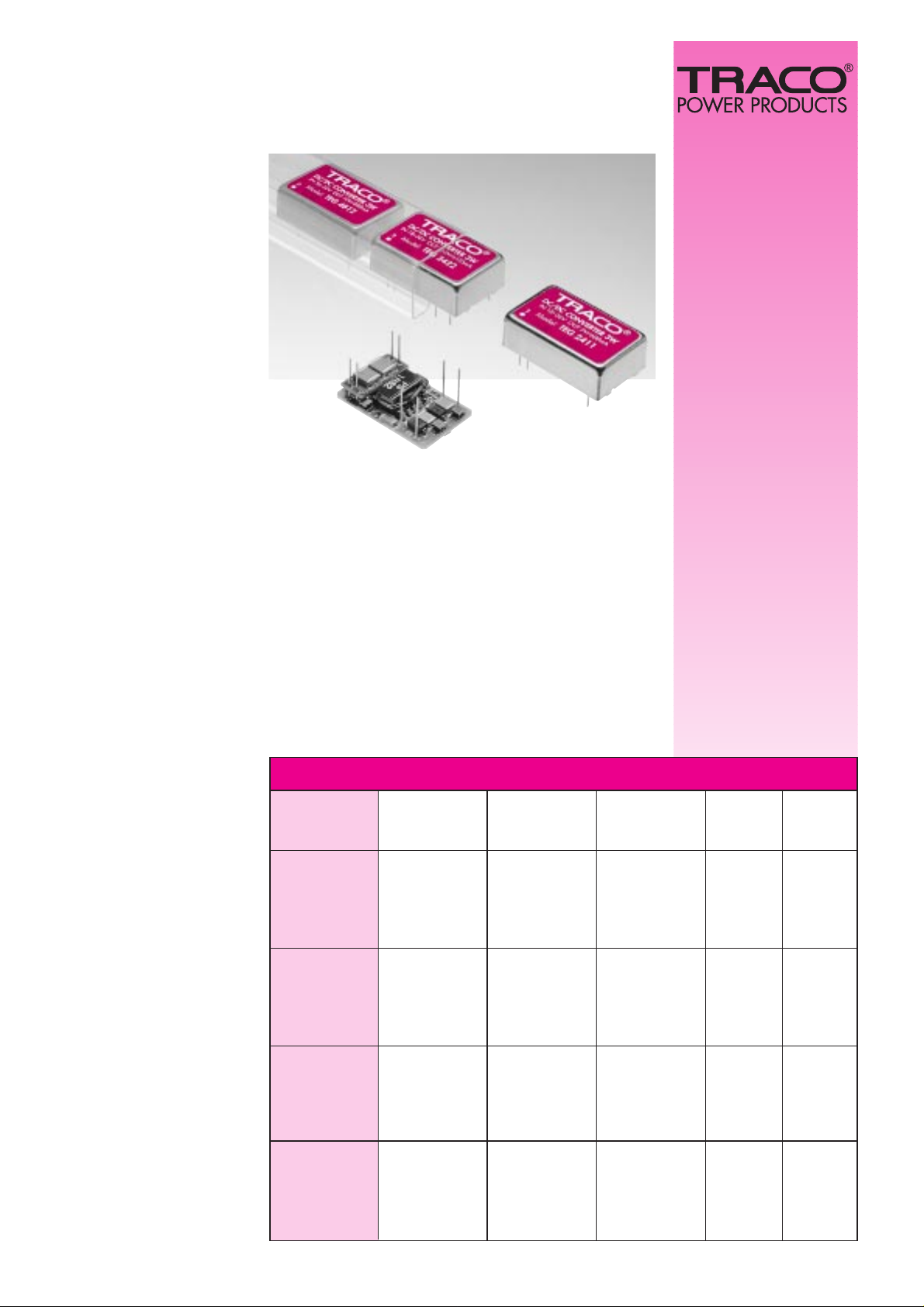
DC/DC-Converter
TEG Series 3 W att
DC/DC-W andler
TEG Serie 3 W att
•
Wide input voltage ranges
•
Regulated outputs
•
High efficiency: 80% typ.
•
No derating up to +75°C
•
I/O-isolation 1’500 VDC
•
EMI complies with EN55022,
CISPR22
•
Metal case for good
RFI-shielding
•
24-pin DIP with industry
standard pin-out
•
Grosse Eingangsspannungsbereiche
•
Regulierte Ausgänge
•
Hoher Wirkungsgrad, 80% typ.
•
Bis +75°C ohne Leistungsrücknahme
•
E/A-Prüfspannung 1’500 VDC
•
Funkentstörung nach
EN55022, CISPR22
•
Metallgehäuse für gute
RFI-Abschirmung
•
24-pin DIP mit
Standard-Pinning
The TEG series are high performance 3W DC/DC converters for space critical applications in distributed
power systems. With built in EMI filter and 1’500VDC
I/O-isolation, they are par ticularly qualified for telecom applications. State of the art SMD-technology with
multi layer ceramic capacitors and a highly automated
production guarantees excellent reliability with a calculated MTBF of >1 Mio. h.
Die TEG Serie sind 3W DC/DC Wandler für Anwendungen mit limitierten Platzverhältnissen in dezentralisierten Stromversorgungssystemen. Mit dem eingebauten Filter für die Funkentstörung und 1’500VDC
E/A-Isolation sind diese DC/DC Wandler ideal für Telecom Anwendungen. Modernste SMD-Technologie
mit Multilayer-Keramikkondensatoren und eine hochautomatisierte Fertigung garantieren höchste Zuverlässigkeit mit einer gerechneten MTBF von >1Mio. Std.
2 years warranty
NEW MODELS
Models / Modelle
Order code Input voltage range Output voltage Output current Input current Efficiency
Bestellnummer Eingangsspannungs- Ausgangsspannung Ausgangsstrom Eingangsstrom Wirkungsgrad
bereich max. 100% load typ.
TEG 0510 3.3 VDC 650 mA
TEG 0511 5 VDC 500 mA
TEG 0512 4.5 – 7 .0 VDC 12 VDC 240 mA 700 mA 75 %
TEG 0522 ± 12 VDC ± 120 mA
TEG 0523 ± 15 VDC ± 95 mA
TEG 1210 3.3 VDC 700 mA
TEG 1211 5 VDC 550 mA
TEG 1212 9 – 18 VDC 12 VDC 250 mA 300 mA 80 %
TEG 1222 ± 12 VDC ± 125 mA
TEG 1223 ± 15 VDC ± 100 mA
TEG 2410 3.3 VDC 700 mA
TEG 2411 5 VDC 600 mA
TEG 2412 18 – 36 VDC 12 VDC 250 mA 150 mA 80 %
TEG 2422 ± 12 VDC ± 125 mA
TEG 2423 ± 15 VDC ± 100 mA
TEG 4810 3.3 VDC 700 mA
TEG 4811 5 VDC 600 mA
TEG 4812 36 – 72 VDC 12 VDC 250 mA 75 mA 82 %
TEG 4822 ± 12 VDC ± 125 mA
TEG 4823 ± 15 VDC ± 100 mA
All specifications valid at nominal input voltage, full load
and +25°C after warm-up time unless otherwise stated
Alle Spezifikationen gültig bei Nominal-Eingangsspannung, V ollast
und +25°C nach Aufwärmzeit, ausgenommen anders spezifiziert
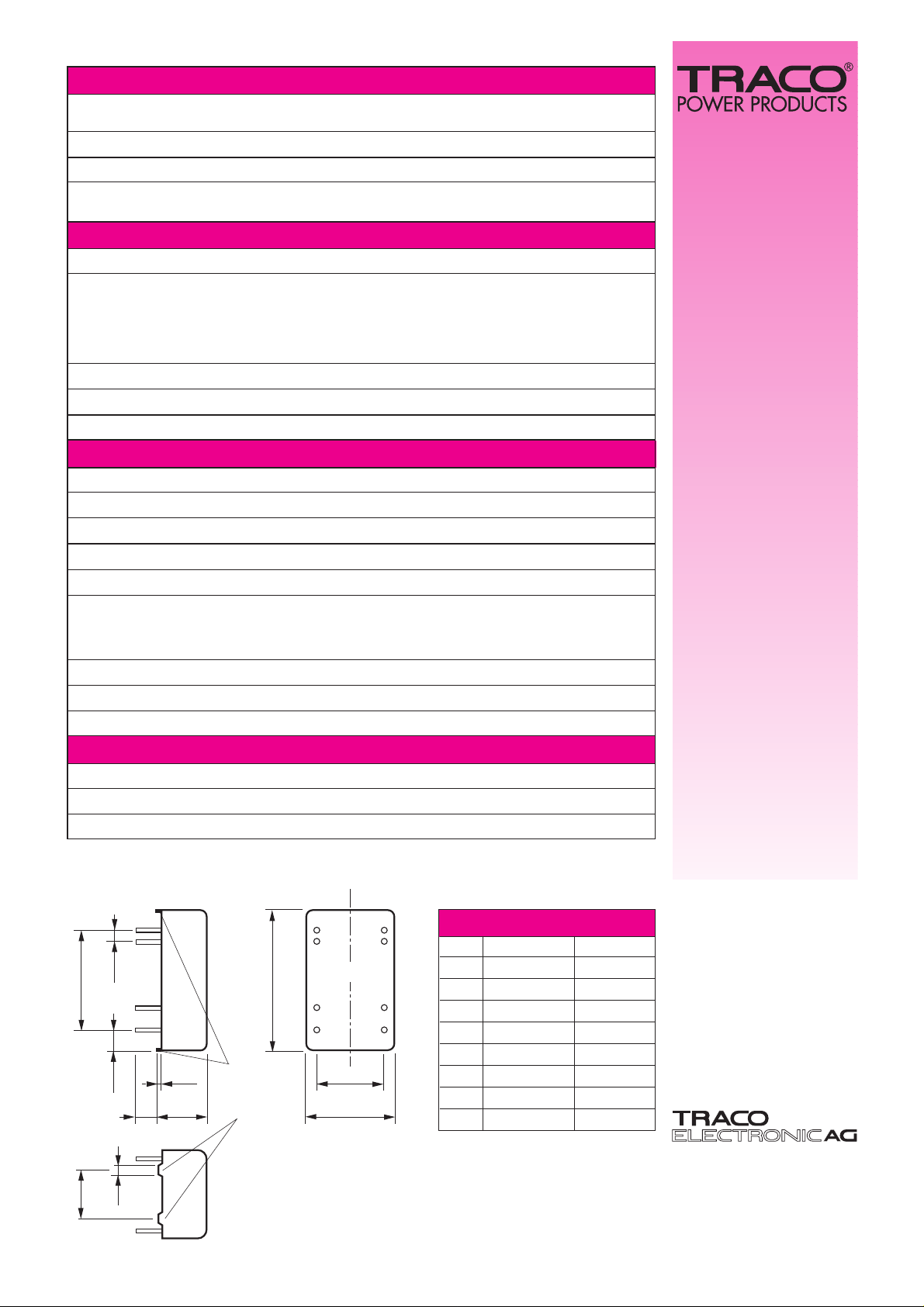
22.86
20 ±0.5
2.54
4.54
32
±0.5
10
0.5
5
15.24
9
11
22
23
2
3
16
14
Built-in
stand-offs
to ease PCB
cleaning
(0.9)
(0.1)
(0.18)
(1.25 ±0.02)
(0.4)
(0.02)
(0.2)
(0.79
±0.02)
(0.6)
2.0
(0.43)
(0.08)
Bottom view
10.86
Specifications can be changed without notice
Pins
ø
0,5mm (0.02)
( ) = inch
T echnische Änderungen vorbehalten
08/97
Jenatschstrasse 1
CH-8002 Zürich/Switzerland
T el. +41-1-284 29 11
Fax +41-1-201 11 68
Input Specifications Eingangsspezifikationen
Input current (no load) Eingangsstrom (Leerlauf) 24 VDC models: 15 mA typ.
48 VDC models: 10 mA typ.
Reflected input current Reflektierter Eingangsstrom 50 mA pk-pk typ.
Input filter Eingangsfilter internal filter
EMI (conducted) Funkentstörung (leitungsgebunden) EN 55022 class A, CISPR 22 class A
with parallel MKT capacitor 1µF at input mit parallelem MKT Kondensator 1µF am Eingang EN 55022 class B, CISPR 22 class B
Output Specifications Ausgangsspezifikationen
Voltage accuracy Einstellgenauigkeit ± 3 %
Regulation Regelabweichungen
– Input variation – Eingangsspannungsänderung ± 0.5 % max.
– Load variation 10 – 100 % – Laständerung 10 – 100 %
– single output – einfach Ausgang ± 1.0 % max.
– dual output balanced – dual Ausgang symmetrisch ± 1.0 % max.
– dual output unbalanced – dual Ausgang asymmetrisch ± 2.0 % max.
Ripple and noise (20 MHz Bandwidth) Restwelligkeit (20 MHz Bandbreite) 60 mVpk–pk max.
T emperature coefficient T emperatur-Koeffizient ± 0.05 % / °C
Short circuit protection Kurzschlussicherheit continuous / dauernd
General Specifications Allgemeine Spezifikationen
Operating temperature range Betriebstemperaturbereich – 25°C … +75°C
Case temperature Gehäusetemperatur + 95°C max.
Storage temperature range Lagertemperaturbereich – 40°C … +105°C
Humidity (non condensing) Feuchtigkeit (nicht betauend) 95 % rel H max.
Reliability, MTBF (MIL-HDBK-217 E) Zuverlässigkeit, MTBF (MIL-HDBK-217 E) >1'000'000 h / at + 25°C
Isolation voltage Prüfspannung
– Input / Output – Eingang / Ausgang 1’500 VDC / 1 Min.
– Input / Case – Eingang / Gehäuse 500 VDC / 1 Min.
– Output / Case – Ausgang / Gehäuse 500 VDC / 1 Min.
Isolation capacity I/O Isolationskapazität E/A 500 pF typ.
Isolation resistance I/O Isolationswiderstand E/A > 1000 MOhm
Switching frequency Schaltfrequenz 250 – 850 kHz typ.
Physical Specifications Physikalische Spezifikationen
Case material Gehäusematerial
steel nickel plated / Stahl vernickelt
Potting material Vergussmasse Silicon rubber TSE (UL 94 V-0)
Soldering temperature Löttemperatur max. 260 °C / 10 sec.
Pin-Out
Pin Single output Dual output
2 – V in – V in
3 – V in – V in
9 No Pin Common
11 No connection – V out 2
14 + V out + V out 1
16 – V out Common
22 + V in + V in
23 + V in + V in
 Loading...