

Page 1
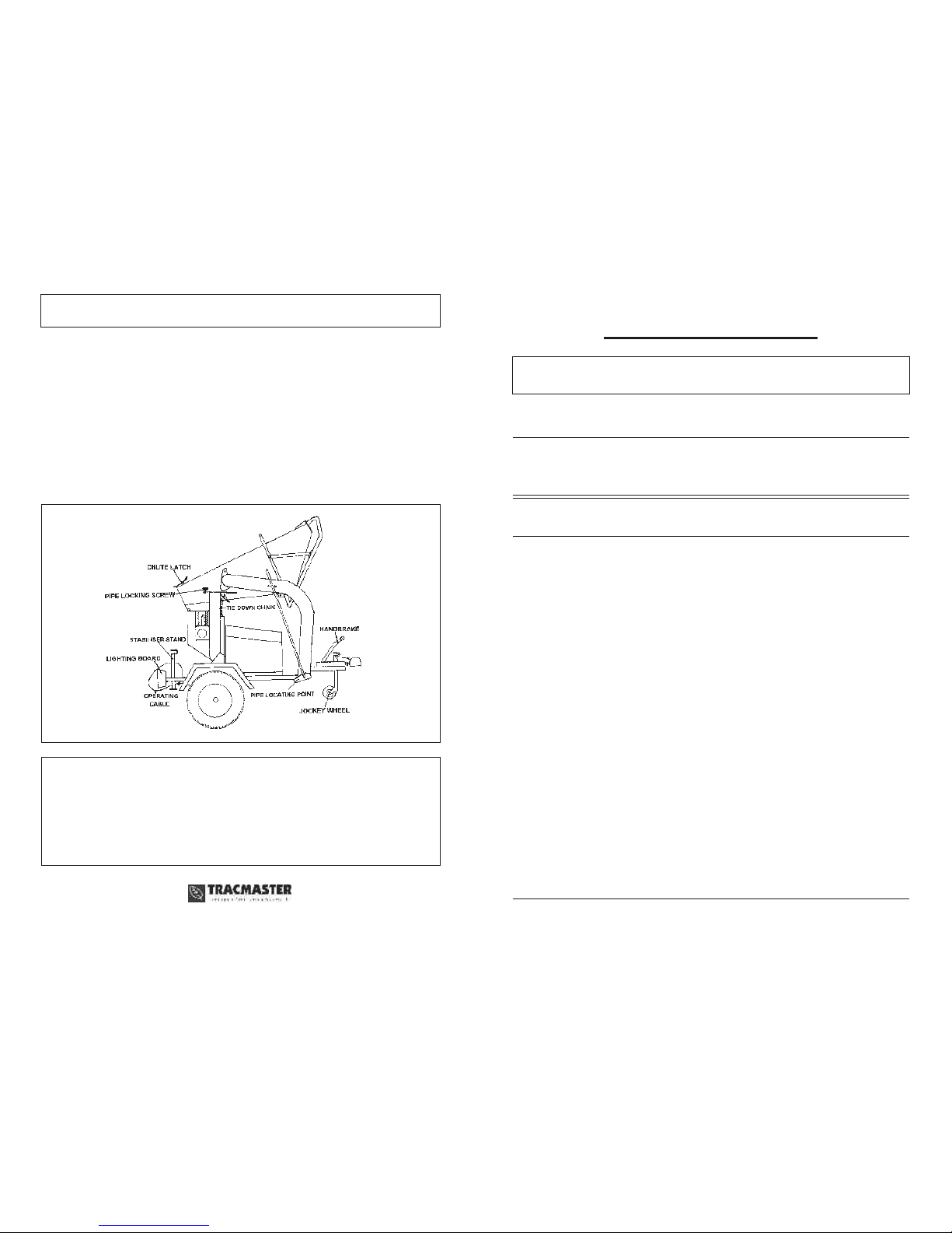
TOWING
(Fig. 2)
Undo the flap adjuster screw.
Release the pipe locking clamp and lower the pipe into the pipe locating bracket.
Tighten the flap adjuster screw.
Unhook the operating cable from the actuating arm and clip back round chassis.
Raise the rear stabiliser and lock into place.
Check lighting board operation.
Check handbrake is OFF before towing.
Check operation of jockey wheel and that it is raised before towing.
PETROL MODEL
CAMON
IMPORTANT - PLEASE READ CAREFULLY
OPERATING INSTRUCTIONS
& SAFETY NOTES
C250 WOOD CHIPPER
No liability will be accepted for any damage caused to persons or property
through failure to observe operating and safety instructions.
SAFETY
ALWAYS start the engine in the open air
DO NOT smoke when refuelling
ALWAYS stop the engine and the machine before making any
adjustments, refuelling, moving or cleaning or when the unit is unattended
ALWAYS ensure that guards are in place when the machine is operating
or the engine is running
DO NOT remove any safety guards that are fitted
ALWAYS wear suitable clothing and footwear to give personal protection
ALWAYS wear safety glasses and ear protectors
KEEP hands, feet and clothing out of openings, discharge and moving parts
when the machine is operating or the engine is running
DO NOT touch any moving parts or attempt any maintenance whilst the
machine is running - KEEP HANDS AND FEET AWAY
DO NOT allow children or anyone uninstructed to operate the machine -
KEEP ANIMALS AWAY
IF A FAULT develops DO NOT attempt any repair - immediately contact
the supplier from whom the machine was obtained
C250P/0904
Fig. 2
Teknol House, Victoria Road, Burgess Hill RH15 9LH
Tel: 01444 247689 Fax: 01444 871612
Website: www.tracmaster.co.uk E-mail: [email protected]
Page 2
OPERATION
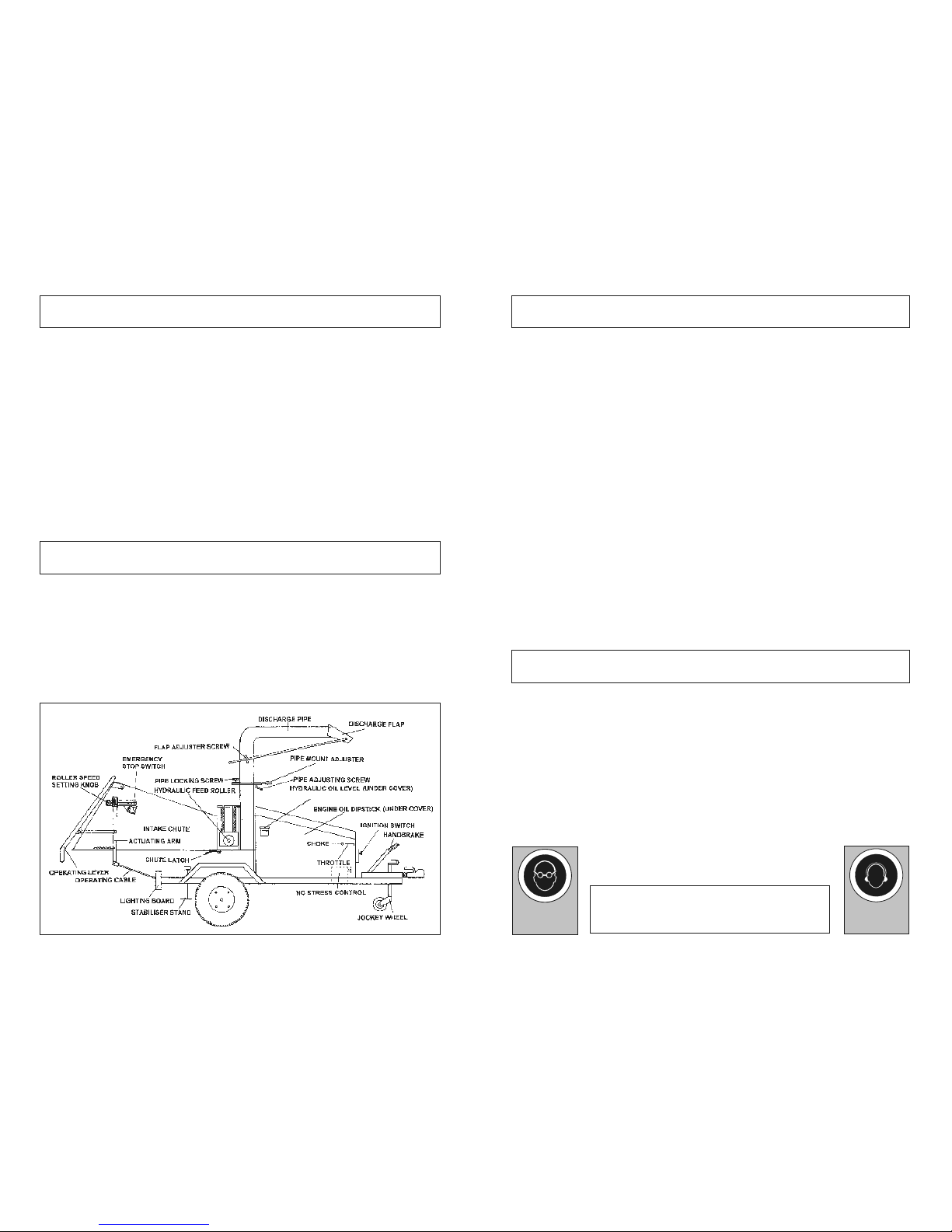
(Fig. 1)
The Chipper can handle a MAXIMUM 5” DIAMETER branches. Increase the engine to FULL
throttle, allow the machine to build up to its FULL operating speed and leave for two minutes to
warm up.
Check the reverse operation of the hydraulic feed roller by pushing the operating lever towards the
engine. Do not press the lever beyond the reverse position otherwise the emergency stop switch
will be activated which will stop the engine.
Set the speed of the hydraulic feed roller by adjusting the setting knob up or down the adjusting slot
as required.
It is best to start off the rollers on a slow setting - the speed can be increased for small branches if
required but for the large branches it must be reduced.
Gently feed in the timber until it is gripped by the feed rollers - once gripped, let go of the timber and
the machine will feed itself at the pre-set roller speed.
Feed only one branch at one time - NEVER PUT TWO OR MORE BRANCHES IN TOGETHER.
If the rollers jam push the operating lever forwards towards the engine to reverse the rollers and
drive the branch back out.
In the event of any serious occurrence press the operating lever fully to activate the Emergency
Stop.
Attempting to overfeed the machine with too large a branch or too high feed roller speed may cause
damage. The machine is designed to handle only timber - DO NOT PUT ANY OTHER TYPE OF
MATERIAL INTO THE MACHINE.
FINISHING WORK
Once the work has finished, allow the machine to continue running at full speed for one minute to
ensure the rotor housing is completely clear of debris.
Slowly reduce the engine throttle to tick over then switch off the ignition switch. BE CAREFUL OF
HOT EXHAUST.
NB Rotor will continue to rotate silently for a short time after the engine is switched off. Ensure
the rotor is stationary before attempting any cleaning or opening of rotor housing.
ENSURE THAT THE IGNITION SWITCH IS LEFT IN THE OFF POSITION. Stopping the engine
by using the emergency stop switch and leaving the ignition switched on will result in a flat battery.
BEFORE STARTING
Ensure the machine is on firm, level ground and that the handbrake is ON. DO NOT USE MACHINE
ON A SLOPE. (Fig. 1)
Lower the rear stabiliser onto the ground and lock in to place. (Fig. 1)
Remove the clips retaining the infeed chute extension and lower the chute to the operating position.
Secure in place with the retaining clips. (Fig. 2)
Connect the operating cable to the actuating arm. (Fig. 1)
Undo the flap adjuster screw. (Fig. 2)
Unhook the discharge pipe from its transport position. Raise the pipe and secure it into the
operating position with the pipe locking clamp. (Fig. 1)
Set the discharge pipe in the required direction of discharge and set the angle of the outlet flap.
Tighten the flap adjuster screw. (Fig. 2)
Check the engine oil level. (Fig. 1)
Check the hydraulic oil level in header tank. (Fig. 1)
Check fuel level. Only use unleaded petrol from a clean container. (Fig. 1)
TO START ENGINE
(Fig. 1)
Ensure the emergency stop switch is released and the “No-Stress” Control panel is switched on.
If the engine is cold, apply the choke.
Set the throttle to quarter speed.
Turn ignition switch to start the engine and release back to run position once the engine has started.
Release the choke and return throttle to idle.
NB The engine cannot be started unless the intake chute is latched down and the engine cover is
down. Lock-out switches on the chute and cover prevent this.
Fig. 1
Noise emissions up to 104dB(A)
Ear defenders to be worn to BS 6344
GOGGLES
must be worn when
using this machine
Wear
ear protectors
 Loading...