

Page 1
User Manual
SERIES II
Page 2

Page 3

TABLE OF CONTENTS
TABLE OF CONTENTS ....................................................................................... 3
INTRODUCTION TO BRT PRODUCTS ................................................................. 7
WELCOME! ......................................................................................................... 7
VISUAL OVERVIEW OF THE SYSTEM ................................................................. 8
IN CAB ................................................................................................................ 8
TYPES OF SUPPORTED SENSORS ................................................................................ 8
OPTIONAL ACCESSORIES AVAILABLE .......................................................................... 8
THE BRT 5 MONITOR ....................................................................................... 9
FRONT VIEW ........................................................................................................ 9
BACK VIEW ........................................................................................................ 10
START-UP SCREEN .............................................................................................. 10
INITIAL START-UP PROCEDURE ............................................................................... 11
BASIC NAVIGATION PRINCIPLES .............................................................................. 12
SET UP ........................................................................................................... 13
TRUCK TYPES ..................................................................................................... 13
SENSORS ........................................................................................................... 14
DATE/TIME ....................................................................................................... 15
LANGUAGE ........................................................................................................ 16
INVERTING LCD ................................................................................................. 17
LARGE NUMBERS ................................................................................................ 18
RESOLUTION ...................................................................................................... 19
SHOW TIME ....................................................................................................... 20
AUTO-BRIGHTNESS ............................................................................................. 21
SELECTION OF AXLE GROUPS IN THE MAIN DISPLAY ..................................................... 22
PRINT SETTINGS ................................................................................................. 23
PRINTER (OPTIONAL) .......................................................................................... 24
PRINTER HEADER ................................................................................................ 25
ALARMS/ LIGHTS ................................................................................................ 26
CONFIGURING THE ALARMS .................................................................................. 27
BRT 5 – User Manual | V1.2.007 | 3
Page 4

PROFILES .......................................................................................................... 28
ADVANCED SCALE FUNCTIONS ............................................................................... 29
ADVANCED ........................................................................................................ 30
SAVING AND LOADING THE CONFIGURATION ............................................................ 30
COPY – PASTE .................................................................................................... 32
SYSTEM TESTS .................................................................................................... 33
COMMUNICATION .............................................................................................. 34
SPECIAL FUNCTIONS ............................................................................................ 35
CALIBRATION ................................................................................................ 38
EMPTY CALIBRATION ........................................................................................... 39
FULL LOAD CALIBRATION ..................................................................................... 42
USE ................................................................................................................ 45
SCALE FUNCTIONS ............................................................................................... 45
ALARMS/ LIGHTS ................................................................................................ 45
PRINTING .......................................................................................................... 46
UNITS .............................................................................................................. 47
ZEROING ........................................................................................................... 48
DIAGNOSTIC .................................................................................................. 49
CHECKING THE SENSORS ....................................................................................... 49
SYSTEM INFORMATION ........................................................................................ 50
MAINTENANCE .............................................................................................. 51
REPAIRING AN AXLE EQUIPPED WITH AN RT SENSOR .................................................. 51
CLEANING THE MONITOR ...................................................................................... 51
LOAD CELL UNDER THE FIFTH WHEEL ....................................................................... 51
AIR LINE MAINTENANCE ....................................................................................... 51
SPECIFICATIONS ............................................................................................ 52
BRT 5 – User Manual | V1.2.007 | 4
Page 5

LIST OF PARTS ............................................................................................... 53
DISPLAY ............................................................................................................ 53
COMMUNICATION BOX ........................................................................................ 53
RT SENSOR ....................................................................................................... 53
AIR SENSOR ....................................................................................................... 53
LIGHT OPTIONS .................................................................................................. 53
PRINTER OPTIONS ............................................................................................... 53
LOAD CELL OPTIONS ............................................................................................ 53
SEMI-TRAILER INSTALLATION OPTIONS .................................................................... 53
TECHNICAL SUPPORT ..................................................................................... 54
INSTRUCTIONS ON THE MAIN SCREEN ...................................................................... 54
LIMITED WARRANTY ..................................................................................... 55
CALIBRATION SHEET ...................................................................................... 57
CONTACT US .................................................................................................. 58
UPDATE NOTES .............................................................................................. 59
BRT 5 – User Manual | V1.2.007 | 5
Page 6

Page 7

INTRODUCTION TO BRT PRODUCTS
Welcome!
Thank you for purchasing the BRT 5 precision electronic scale. Based on
over 20 years of expertise in research and development, this weighing
system will accurately serve you for years, whether on the road or at the
most difficult sites.
The TrackWeight system’s durability and performance are closely linked
to quality installation and precise calibration. Your authorized dealer has
the know-how to adjust your BRT 5 to meet your needs. If you plan to
install the BRT 5 yourself, no problem. First consult your user manual. It
contains all of the information needed to configure, calibrate and use
your BRT.
If you need technical support, please visit trackweight.com or contact
your authorized dealer.
Thank you again and enjoy your BRT 5!
BRT 5 – User Manual | V1.2.007 | 7
Page 8
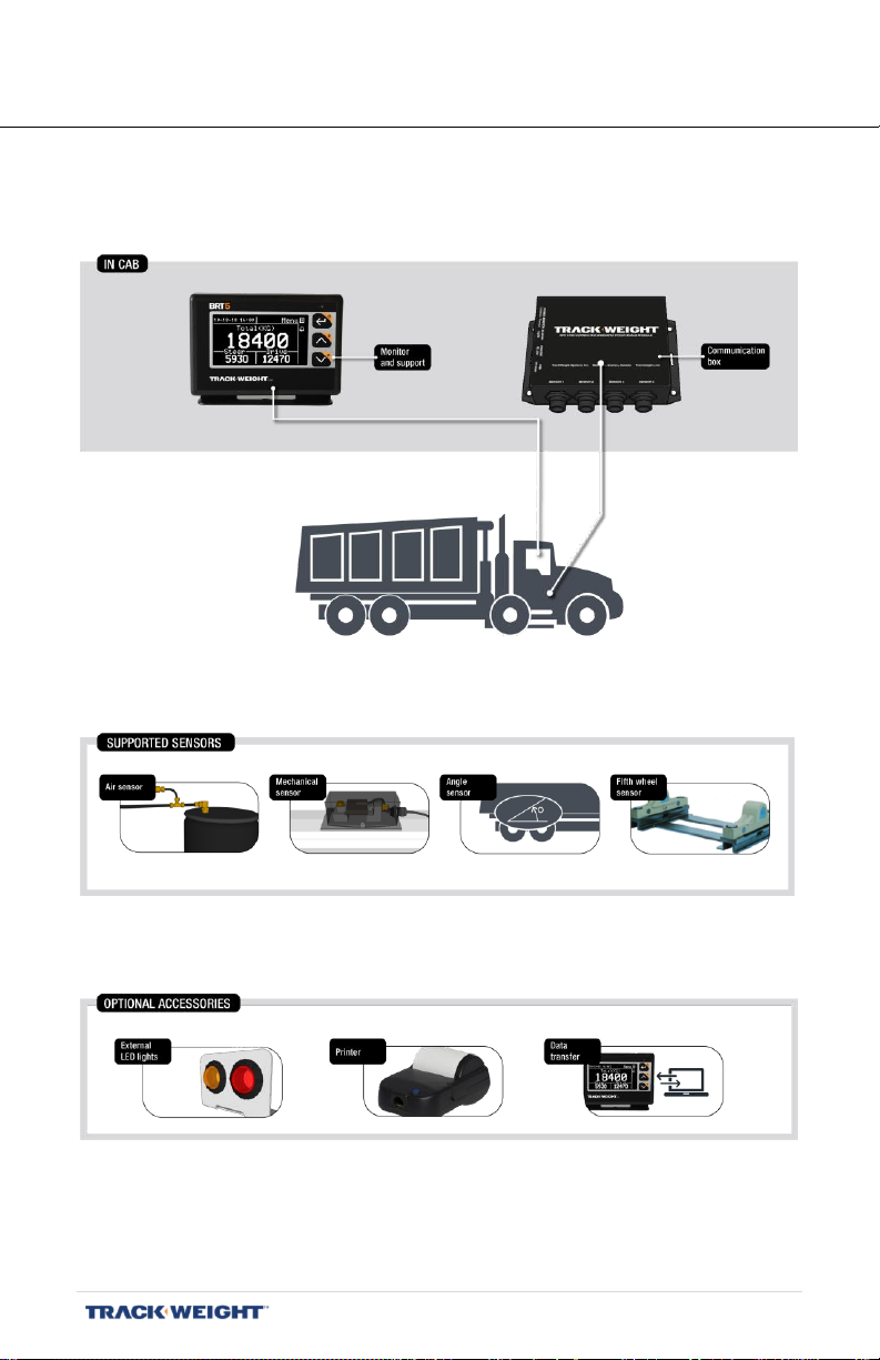
VISUAL OVERVIEW OF THE SYSTEM
In cab
Types of supported sensors
Optional accessories available
BRT 5 – User Manual | V1.2.007 | 8
Page 9
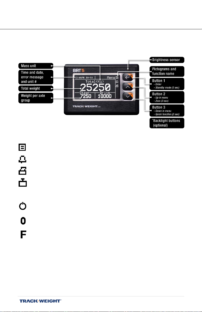
THE BRT 5 MONITOR
Front view
Pictograms Main functions
Menu Calibration and settings access
Alarms Activate/deactivate the alarms
Print Print a data ticket
Units Change unit of measurement (KB, LB)
Special Functions
Standby Hold 3 secs to activate/deactivate standby mode
Zero Hold 3 secs to set to zero function (if function
activated)
Quick Function Hold 3 secs. to access quick functions
Note: See pages 46 to 49 for all function instructions.
Note: If your BRT 5 is equipped with button backlighting, buttons remain
discretely lit at all times.
BRT 5 – User Manual | V1.2.007 | 9
Page 10
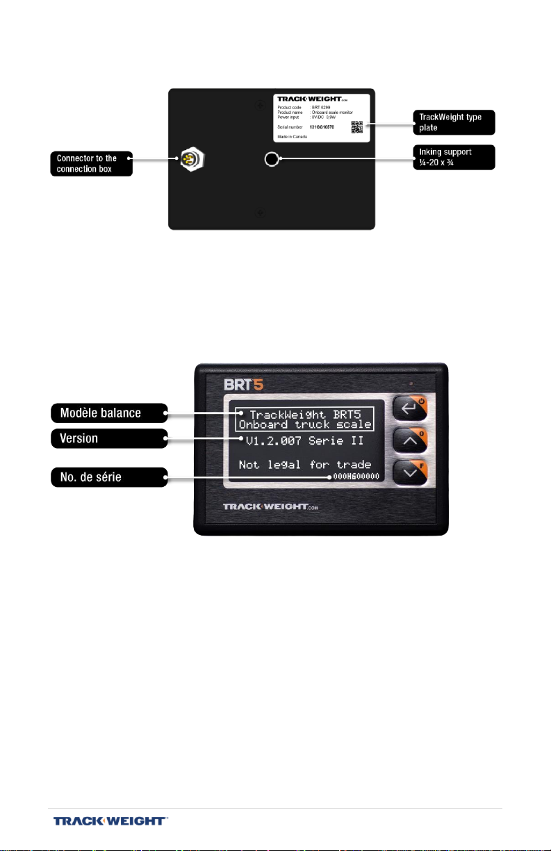
Back view
Start-Up screen
BRT 5 – User Manual | V1.2.007 | 10
Page 11
1
2
3
Initial start-up procedure
1- Selecting the type of truck (p. 13)
2- Configuring the sensors (p. 14 to 12)
3- Configuring the display (p. 15 to 22)
4- Configuring the printer settings (p. 23 to 25)
5- Configuring the alarms, external lights (p. 26 to 27)
6- Calibration (p. 38 to 44)
Note: Certain options and menus are only available when the advanced
functions have been activated. To activate these features,
navigate to “Menu/Setup/Diagnostic” and press the following
buttons in order: 2 - 3 - 2 - 2 - 1.
Note: The advanced functions are automatically disabled when the
device is turned on or after a period of inactivity.
BRT 5 – User Manual | V1.2.007 | 11
Page 12
Basic navigation principles
To adjust/change an option:
1- Using the arrows, select the option you want to change
Press ↵
2- Using the arrows, adjust/change the option
Press ↵
Note: For certain options, it is not required to do the step 2 if they are as
simple as “yes/no”, “on/off”, “activate/deactivate” or
“French/English”.
BRT 5 – User Manual | V1.2.007 | 12
Page 13
Truck types available
Displayed Axle Group
6 Wheels
Steer – Drive
10 Wheels
Steer – Drive
10 Wheels-Pop
Steer – Drv + Pop
10 Wheels Dolly Pop
Str + Drv – Dol + Pop
12 Wheels 2 St
St 1 + St 2 – Drive
Semi-trailer
Tractor – Trailer
B-train
Tractor – Trl 1 + Trl 2
Dray
Str + Drv – Trailer
Dray with Dolly
Str + Drv – Trl + Dol
Wood loader
Str + Drv – Trl + Dol
Vacuum
Steer – Drive
Generic
SET UP
MENU > SET UP
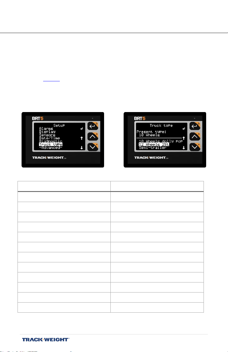
Truck types
[Menu/Setup/Truck Type]
Note: This menu only appears when the advanced functions are activated.
See page 29.
Using the arrows, select the type of truck used. Press ↵ to save the
selection.
BRT 5 – User Manual | V1.2.007 | 13
Page 14
Sensors
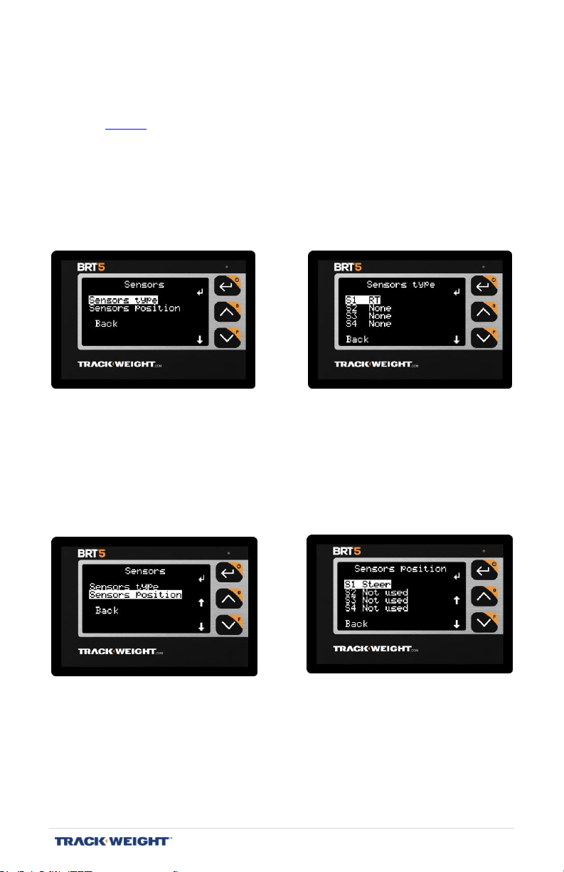
[Menu/Setup/Sensors]
Note: This menu only appears when the advanced functions are activated.
See page 29.
Configure the type of sensors installed, as well as their position on your
truck and / or trailer.
First, select a sensor using the arrows, press ↵ to activate the change.
Select the type of this sensor and press ↵ again to save the selection.
Then, to establish a match between the sensor inputs on the
communication box and the groups of axles, select an entry using the
arrows, press ↵ to activate the modification. Select the instrumented axle
group with this input and press ↵ again to save the selection.
Note: It is appropriate to group all the sensors of the same group of
axles together and connect them in order starting from those
placed in front of the vehicle to those placed in the rear.
BRT 5 – User Manual | V1.2.007 | 14
Page 15
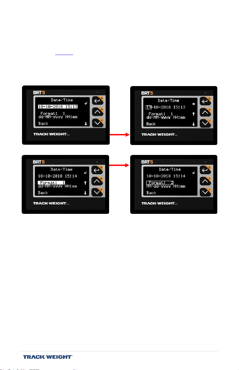
Date/Time
[Menu/Setup/Date/Time]
Note: The date and time are displayed only if the "Show Time" option has been
activated. See page 20.
Adjust the date and time, as well as the type of display (16 choices
available).
BRT 5 – User Manual | V1.2.007 | 15
Page 16
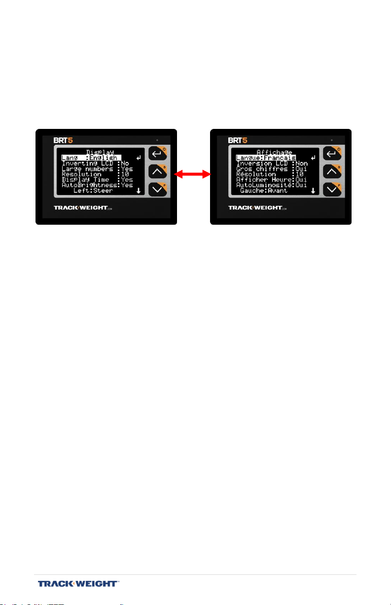
Language
[Menu/Setup/Display/Language]
Select the language you want to use. The choices are:
- English
- French
BRT 5 – User Manual | V1.2.007 | 16
Page 17
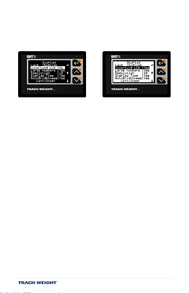
Inverting LCD
[Menu/Setup/Display/Inverting LCD]
Selecting the inverted colour display mode.
BRT 5 – User Manual | V1.2.007 | 17
Page 18
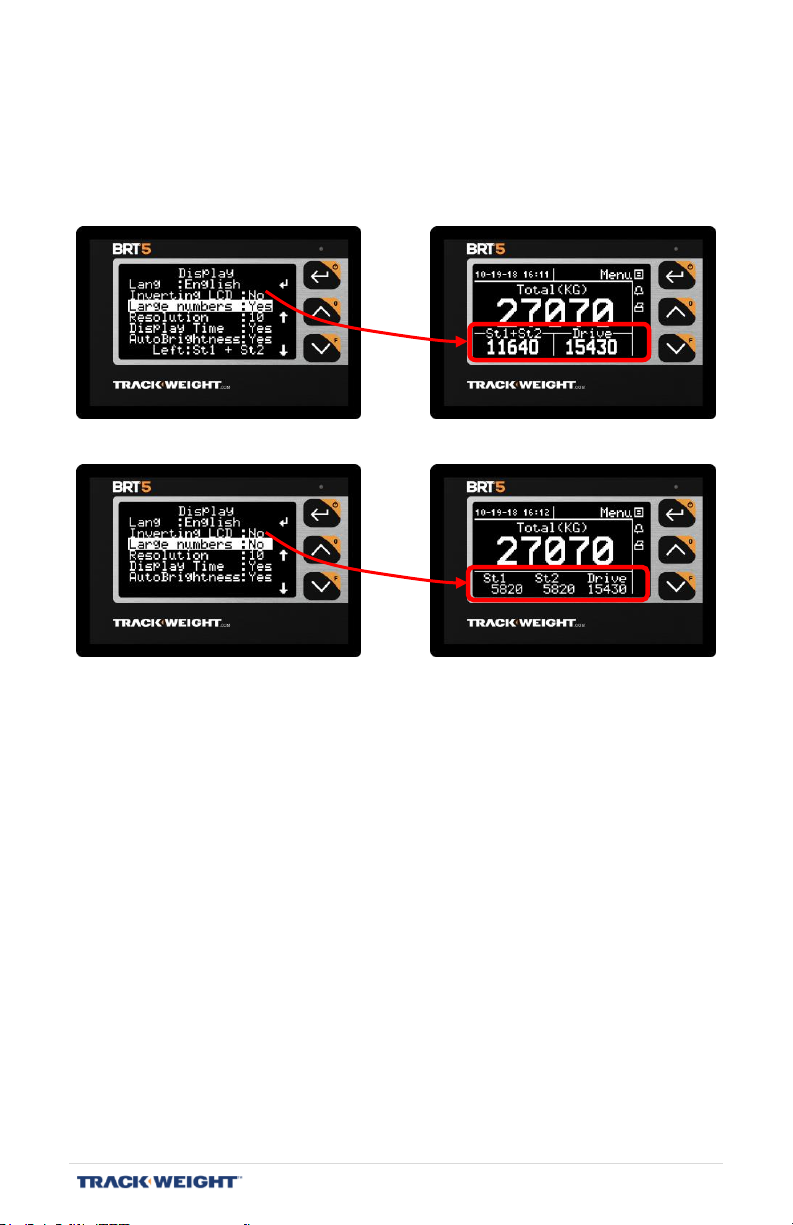
Large numbers
[Menu/Setup/Display/Large numbers]
When selecting the display mode with large numbers, there are two size
options for the axle group numbers: large and small.
BRT 5 – User Manual | V1.2.007 | 18
Page 19
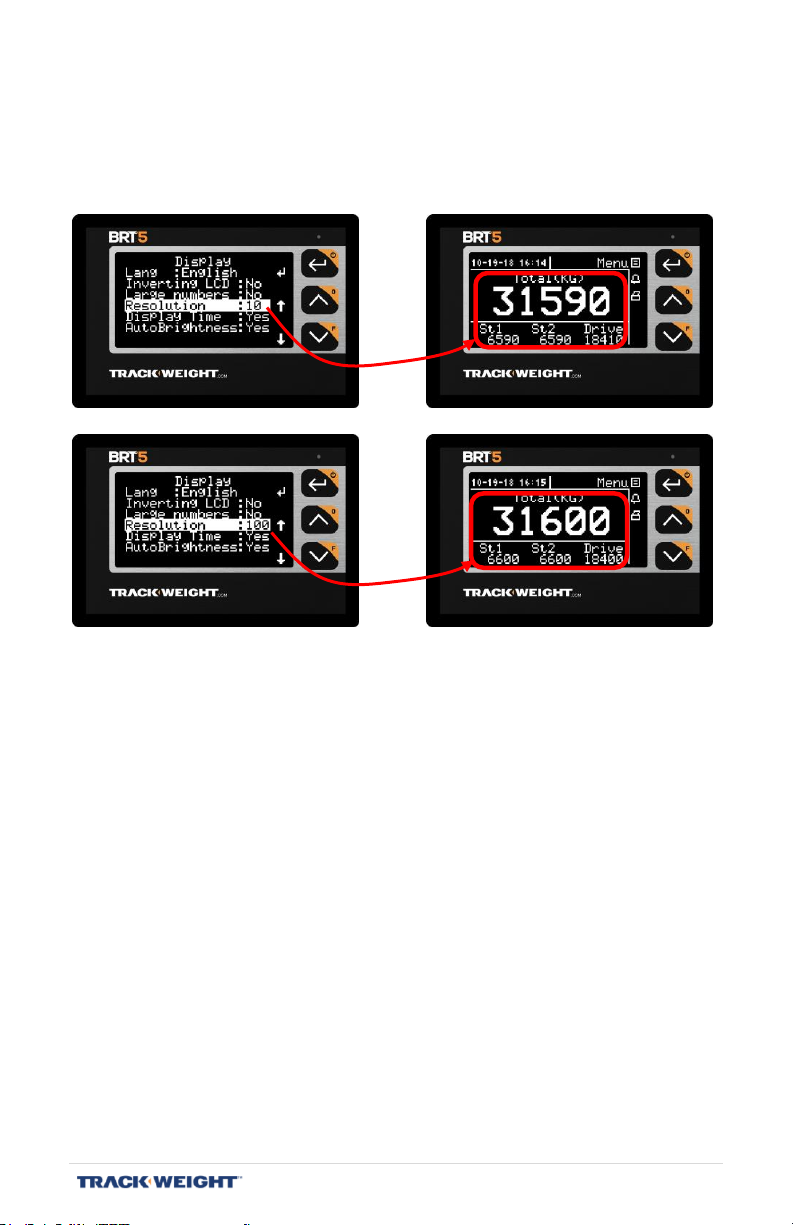
Resolution
[Menu/Setup/Display/Resolution]
Select the value that the weights given on the main display will be
rounded to.
The resolution options are:
- 10
- 50
- 100
Note: Rounding is performed in the unit used (kilograms, pounds).
Note: The scale’s accuracy is not affected by this configuration.
BRT 5 – User Manual | V1.2.007 | 19
Page 20
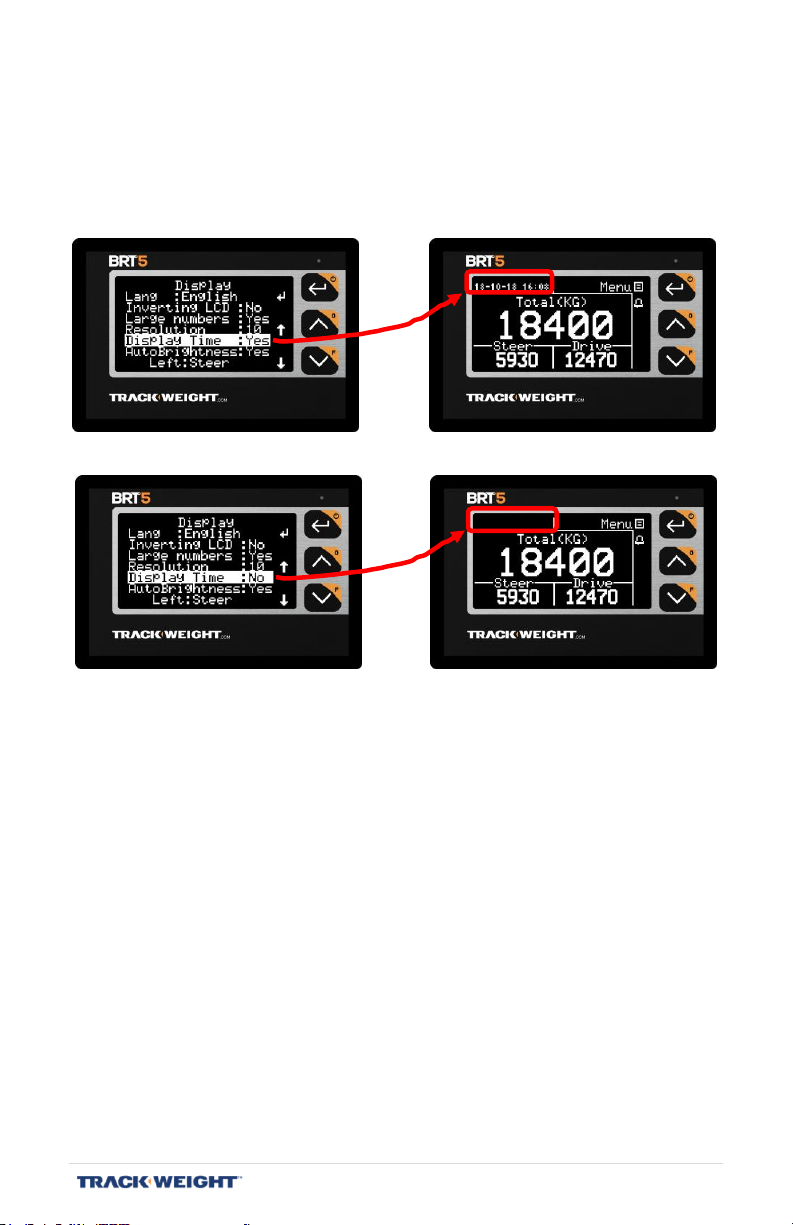
Show time
[Menu/Configuration/Display/Show time]
Enable the display of the date and time on the main screen.
BRT 5 – User Manual | V1.2.007 | 20
Page 21
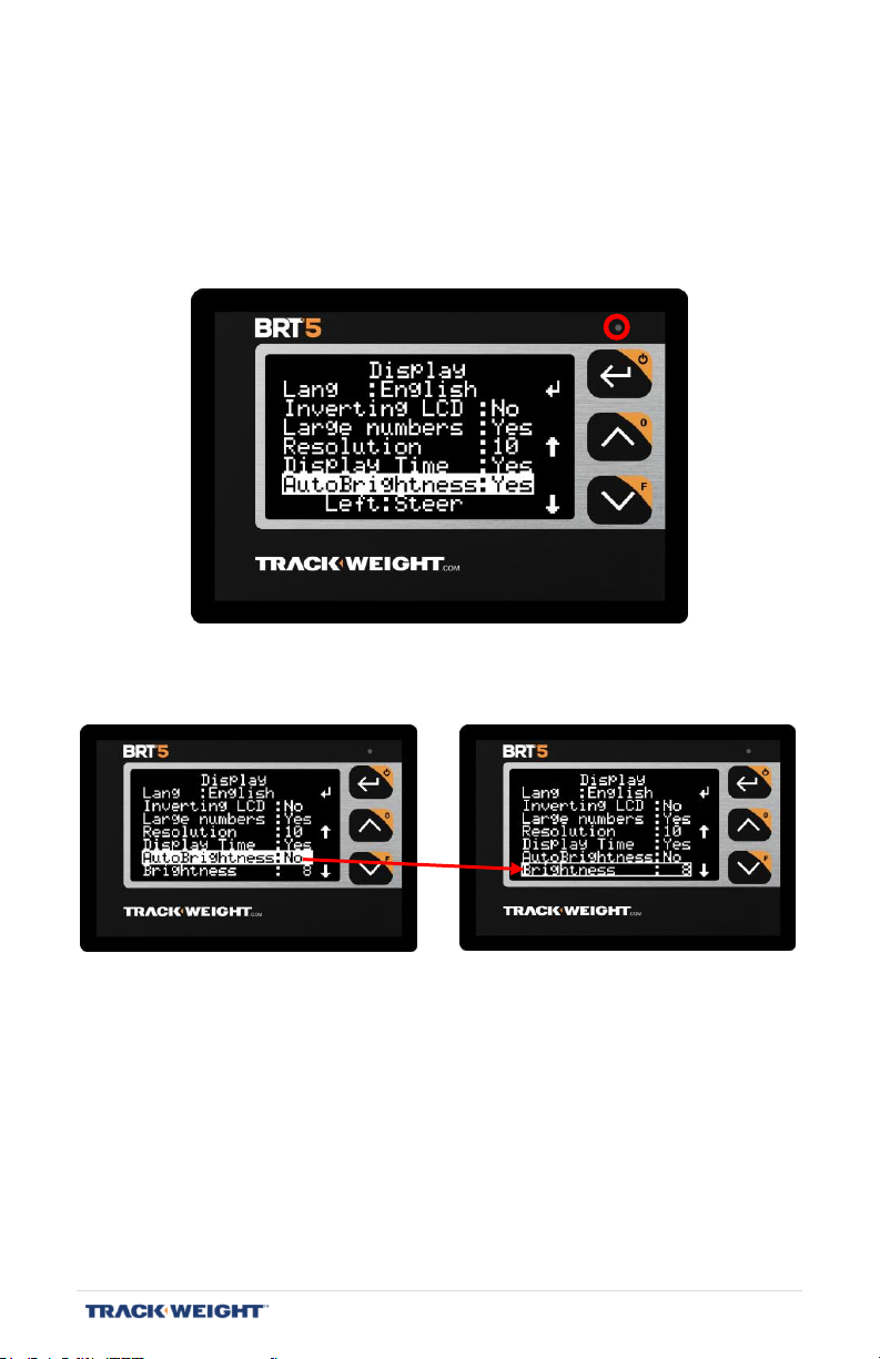
Auto-brightness
[Menu/Setup/Display/Auto-Brightness]
Select the display brightness desired.
Note: Auto-brightness mode is used by default and adjust automatically
the display brightness according to the ambient light.
Disable this mode to choose the degree of brightness permanently.
BRT 5 – User Manual | V1.2.007 | 21
Page 22
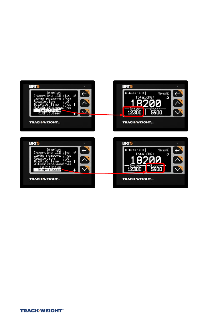
Selection of axle groups in the main display
[Menu/Setup/Display/Left|Right]
In the big numbers display mode, you can select the axle groups
displayed on the main screen.
Note: The choice of axle groups available depends on the type of truck
selected. See “Truck types”, p. 13.
BRT 5 – User Manual | V1.2.007 | 22
Page 23
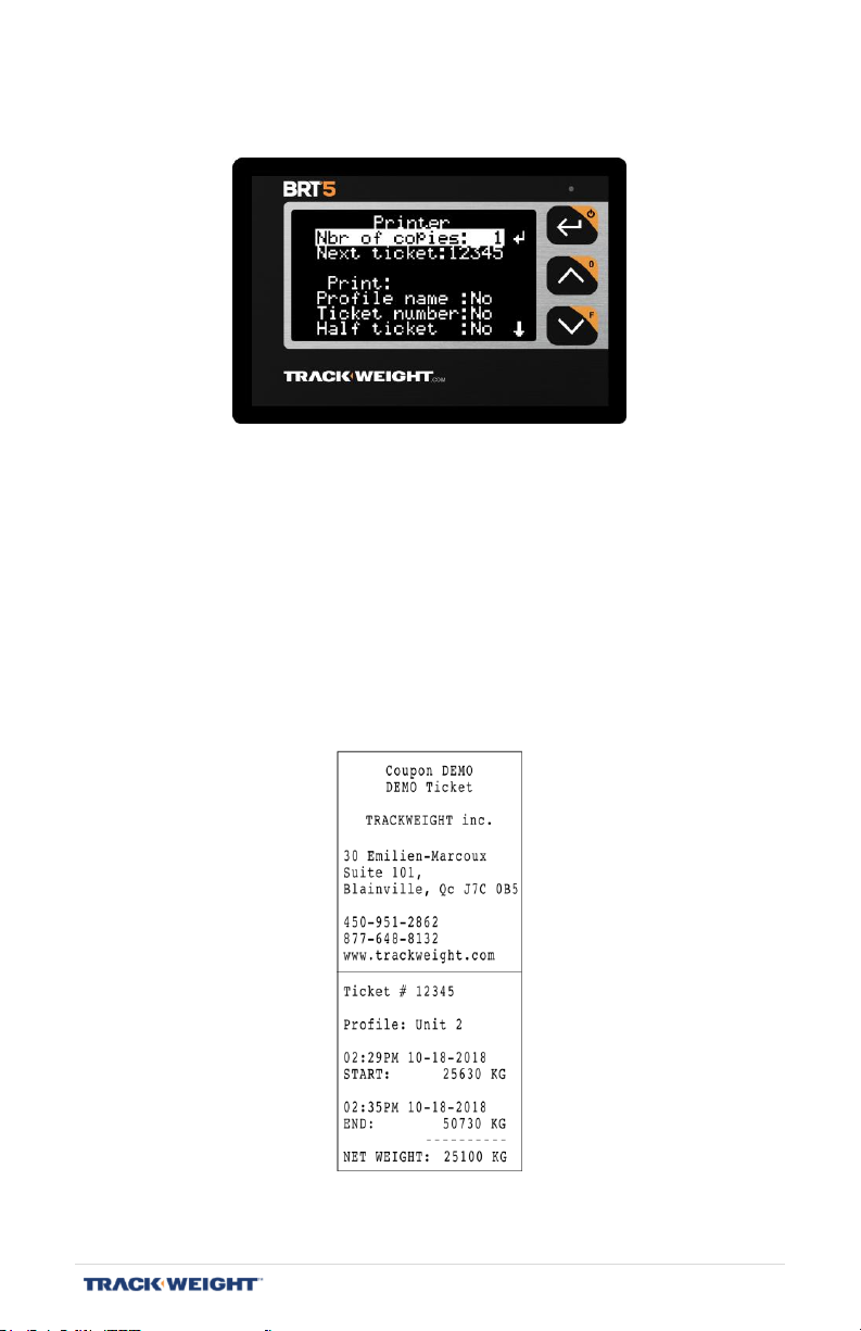
Print Settings
[Menu/Setup/Printer]
Nbr of copies: The number of tickets to be printed.
Next Ticket: Modifies the sequential number of the ticket
Profile name: Determines whether the name of the active
configuration (profile) will be printed.
Ticket number: Determines whether the sequential ticket number
will be printed.
Half ticket: Determines whether the printed ticket will be
abridged.
Standard ticket
with the name and sequential ticket number
BRT 5 – User Manual | V1.2.007 | 23
Page 24
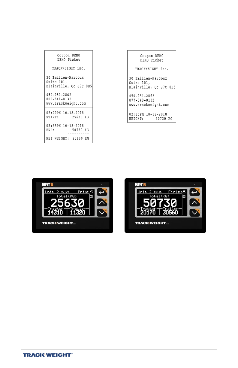
Half Ticket
Printer (optional)
[Menu/Setup/Printer]
Standard Ticket
Printing a standard ticket:
- Using the arrows, select the "Print" pictogram;
- Press button 1 once ("Print");
- Perform the desired operation (loading, unloading);
- Press button 1 ("Finish") again.
Printing an abridged ticket (half-ticket option must be activated):
- Using the arrows, select the "Print" pictogram;
- Press button 1 once (prints the current loading status).
BRT 5 – User Manual | V1.2.007 | 24
Page 25
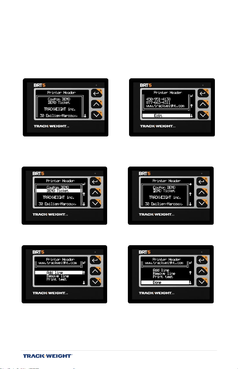
Printer header
[Menu/Setup/Printer/Printer Header]
View/edit the header of printed tickets.
Select “Edit” to make changes.
Press ↵ to edit a line and select the item to be changed. Press the
arrows to change the selected item.
Select “Add line” or “Remove line” to add or remove lines.
BRT 5 – User Manual | V1.2.007 | 25
Page 26
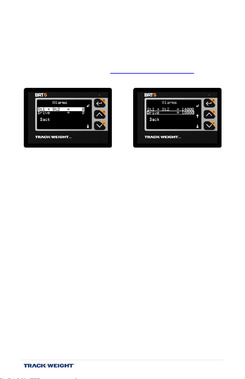
Alarms/ Lights
[Menu/Setup/Alarms (Lights)]
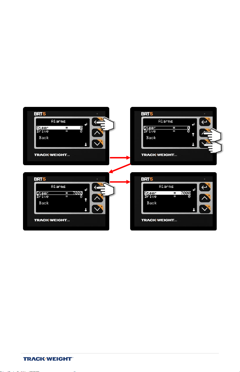
Adjust the value of the alarms per axle group.
Note: The choice of axle groups available depends on the advanced
alarm configuration. See “Configuring the alarms”, p. 27.
Note: The trigger threshold corresponds to the difference between the
alarm value and the value at which the alarm will activate. For
example, if the alarm is set to 7,200 kg with a threshold of
1,000 kg, the corresponding indicator light will flash, with a
progressive period, from 6,200 to 7,200, the weight at which it will
remain on.
BRT 5 – User Manual | V1.2.007 | 26
Page 27

Configuring the alarms
[Menu/Setup/-Advanced-/Alarms Config.]
Note: This menu only appears when the advanced functions are activated. See
page 29.
Select the axle group to use for the alarm.
Menu information:
pg: Configuration page
Ch: Axle group associated with the selectable alarm
Trig: Selectable trigger threshold
Note: The choice of axle groups available depends on the type of truck
selected. See “Truck types”, p. 13.
Note: The trigger threshold corresponds to the difference between the
alarm value and the value at which the alarm will activate. For
example, if the alarm is set to 7,200 kg with a threshold of
1,000 kg, the corresponding indicator light will flash, with a
progressive period, from 6,200 to 7,200, the weight at which it will
remain on.
BRT 5 – User Manual | V1.2.007 | 27
Page 28
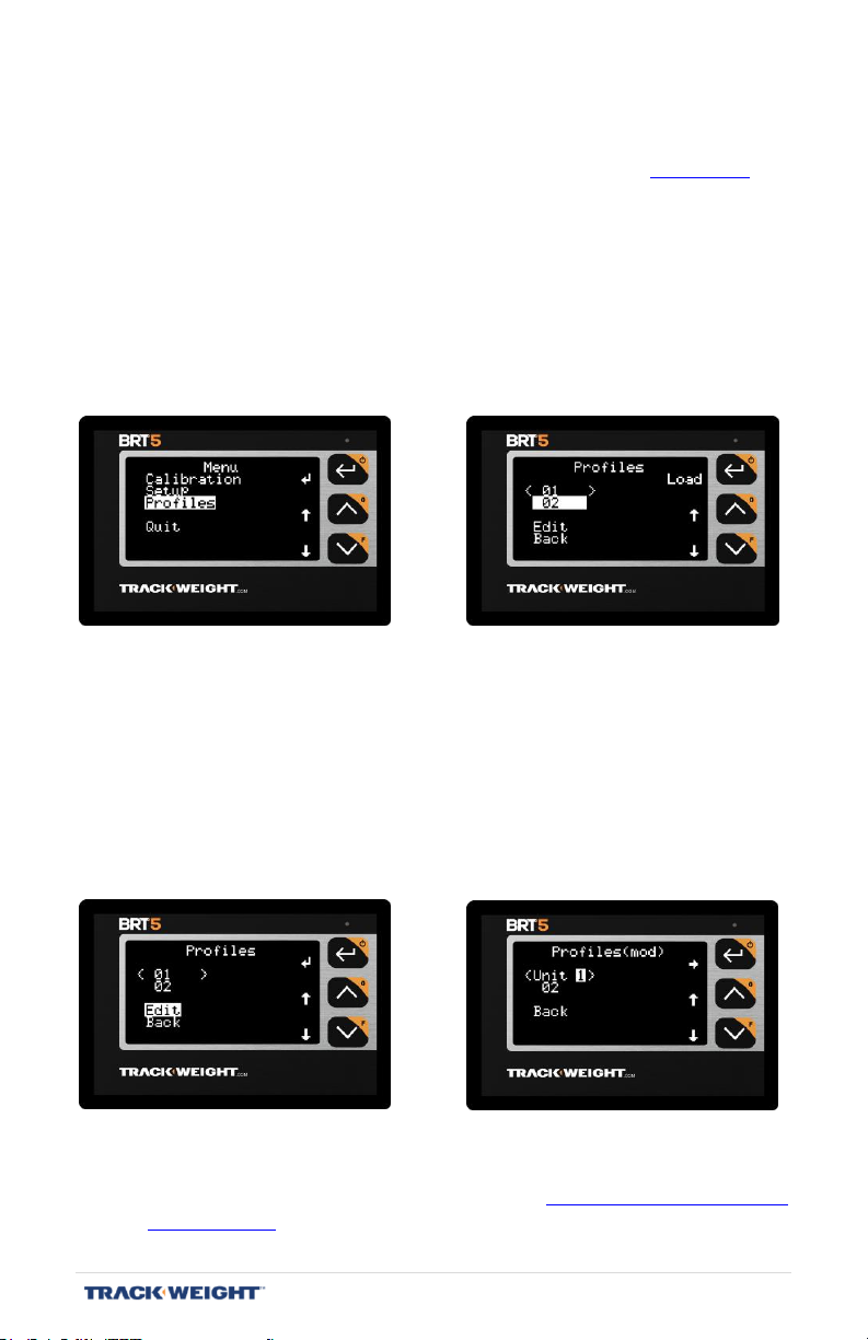
Profiles
[Menu/Profiles]
Note: This menu only appears if the multi-profile option is activated. See page 35.
A backup record is a collection of data including:
- The truck type;
- The sensor type;
- The sensors position;
- The calibration;
- The alarms configuration;
- The display configuration.
The active profile is surrounded by the “<” and “>” symbols.
To activate a different profile, select it using the arrow keys and press ↵.
Note: The name of the profiles can be customized by selecting the "Edit"
function. The chosen name will be displayed on the screen. The
name can contain a maximum of 6 characters.
Note: The maximum number of profiles is adjustable, from 1 to 25, when
the multi-profile option is enabled. See "Special Functions: Multi-
profile", p. 35.
BRT 5 – User Manual | V1.2.007 | 28
Page 29
1
2
3
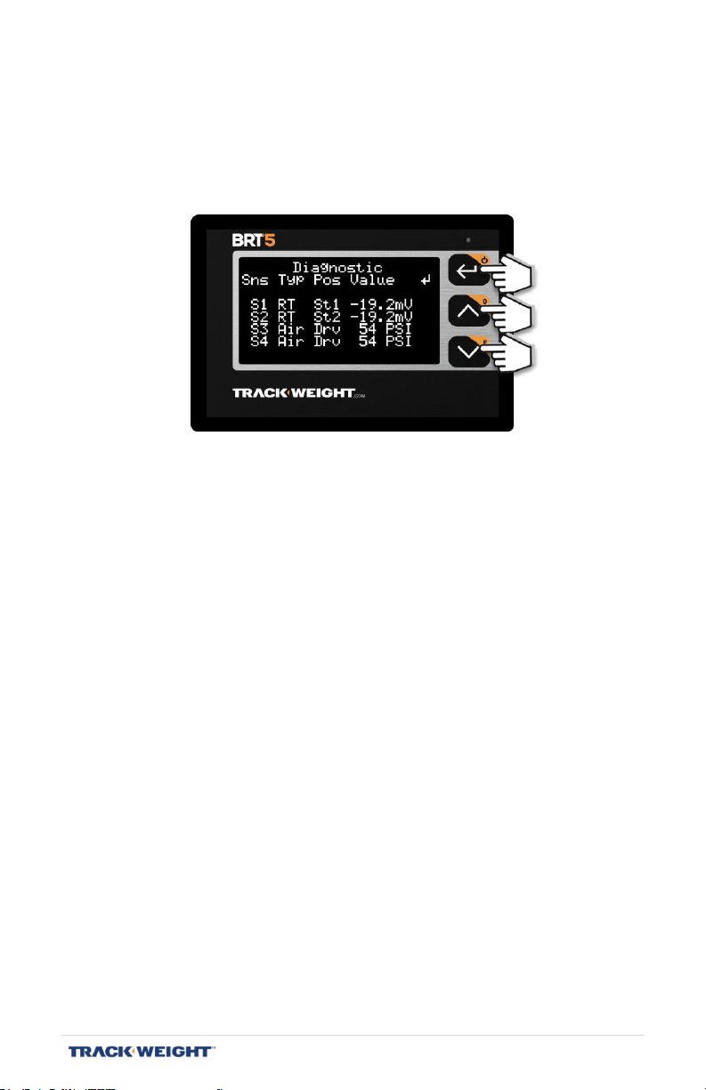
ADVANCED SCALE FUNCTIONS
Certain options and menus are only available if the advanced functions
have been activated. To activate these functions, navigate to
“Menu/Setup/Diagnostic” and press the following buttons in order: 2 - 3
- 2 - 2 - 1.
Note: The advanced functions are automatically disabled when the
device is turned on or after a period of inactivity.
BRT 5 – User Manual | V1.2.007 | 29
Page 30
ADVANCED
[Menu/Setup/-Advanced-]
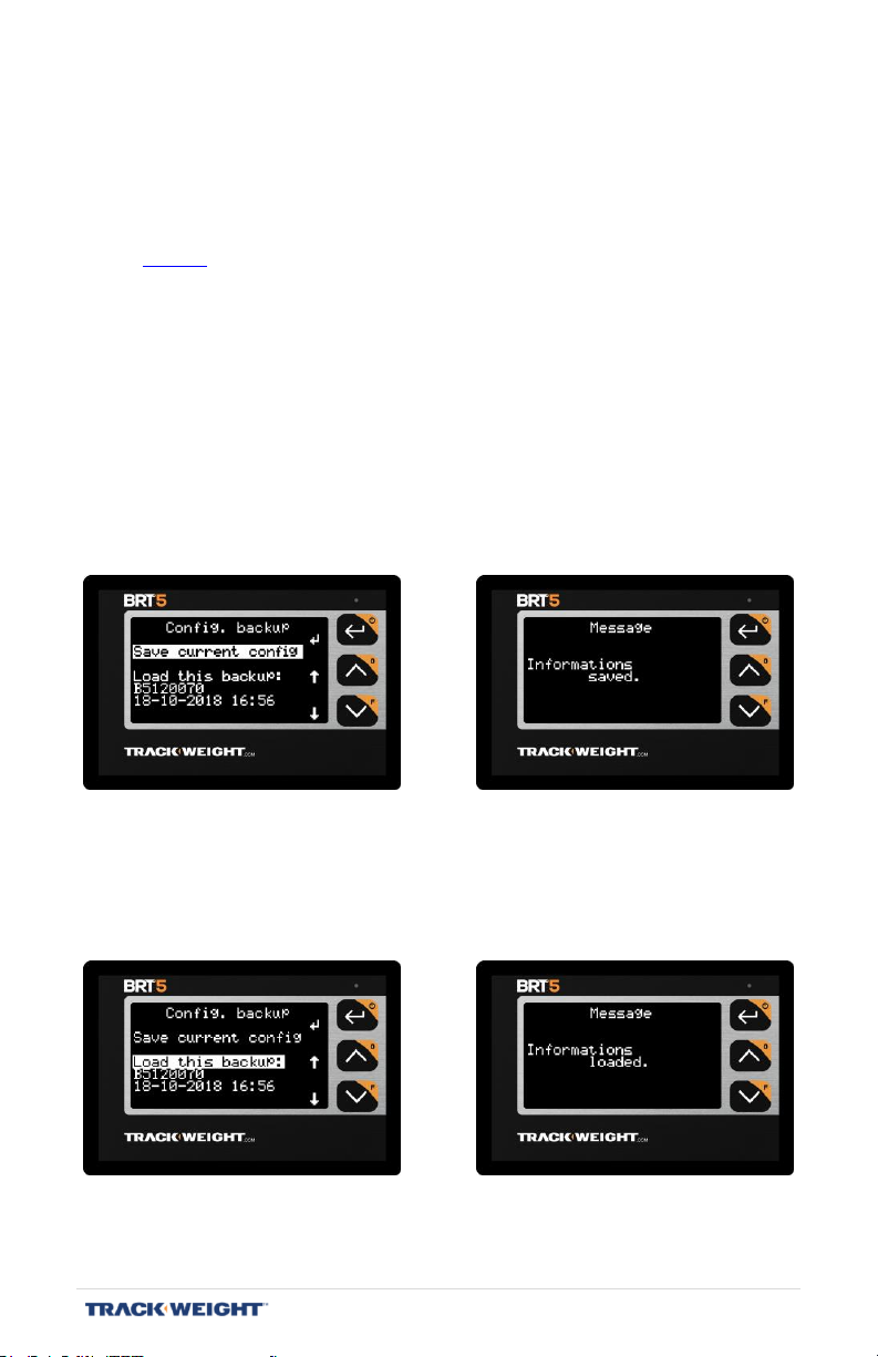
Saving and loading the configuration
[Menu/Setup/-Advanced-/Config. backup]
Note: This menu only appears when the advanced functions are activated. See
page 29.
Save and restore the overall configuration as well as the current profile in
the communication box.
Note : Make sure you are on the profile you want to back up.
To save the global configuration and the current profile, select “Save
current config.” using the arrow keys and press ↵.
To retrieve a previously recorded data set, select it using the arrow keys
and press ↵.
BRT 5 – User Manual | V1.2.007 | 30
Page 31

The content of data sets
A "profile" includes the following specific configurations:
- The truck type;
- The sensor type;
- The sensors position;
- The calibration;
- The alarms configuration;
- The display configuration.
The overall configuration includes the following:
- The number of the profile in use;
- The print configuration (except the client header);
- The language used;
- The advanced options used.
BRT 5 – User Manual | V1.2.007 | 31
Page 32
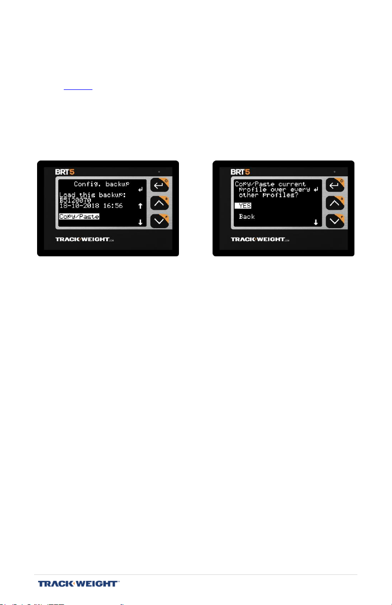
Copy – paste
[Menu/System/-Advanced-/Config. backup/Copy/Paste]
Note: This menu only appears when the advanced functions are activated. See
page 29.
Duplicate the current profile’s specific configuration and apply them to all
the other available profiles. This makes it easier to create multiple
profiles with similar parameters.
BRT 5 – User Manual | V1.2.007 | 32
Page 33
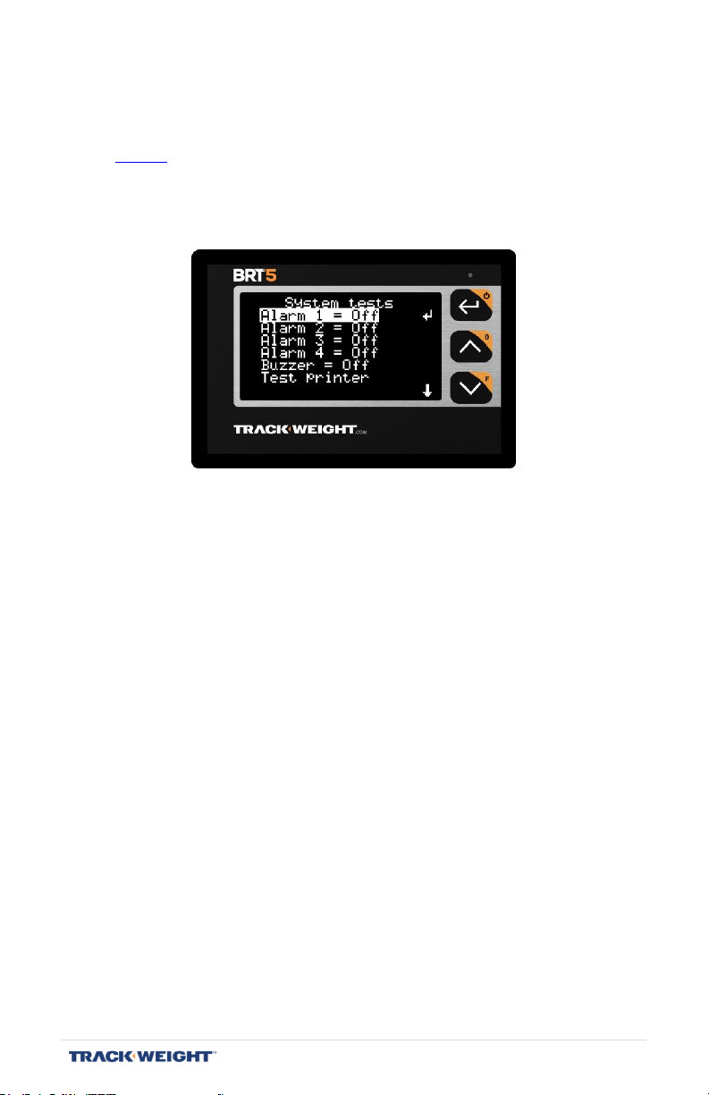
System tests
[Menu/System/-Advanced-/System tests]
Note: This menu only appears when the advanced functions are activated. See
page 29.
Allows you to test the alarms, buzzer and printer.
BRT 5 – User Manual | V1.2.007 | 33
Page 34
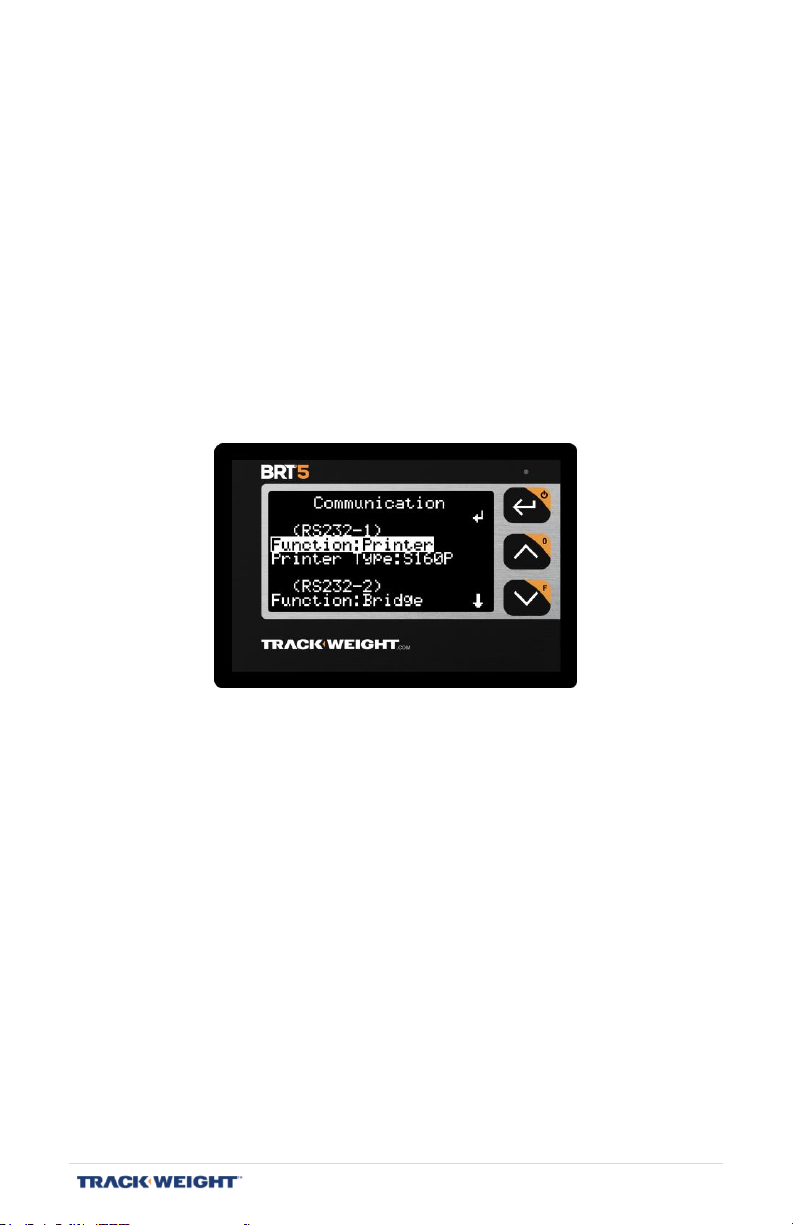
Communication
[Menu/System/-Advanced-/Communication]
Note: This menu only appears if advanced functions are enabled. See page 29.
Configure the two available RS-232 ports of the communication box.
The available choices are:
- Printer
- Server (communicate with a terminal, for example, a PC)
- Bridge (communicate only with the monitor)
- Undefined (unused port)
BRT 5 – User Manual | V1.2.007 | 34
Page 35
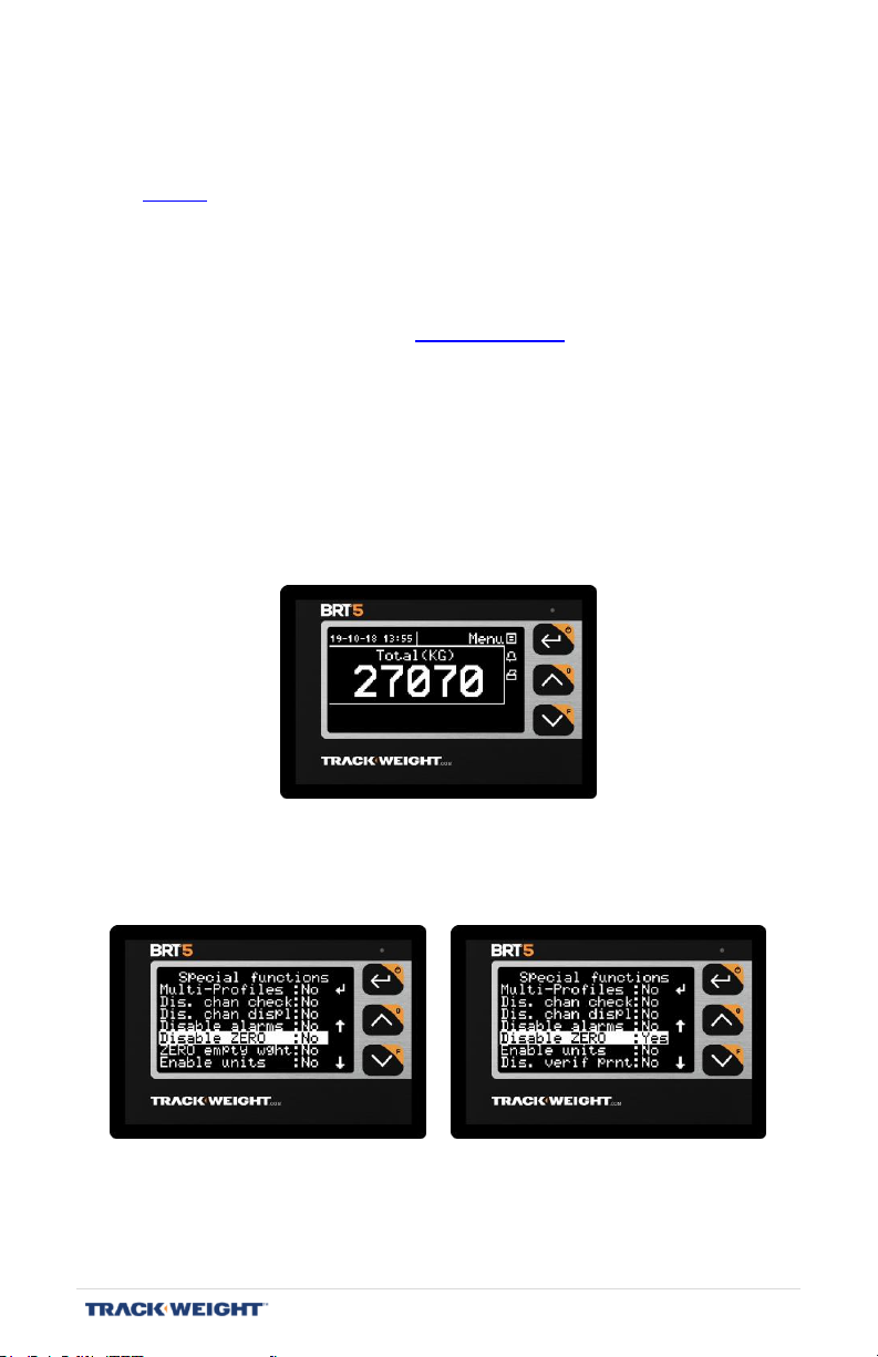
Special functions
[Menu/System/-Advanced-/Special functions]
Note: This menu only appears when the advanced functions are activated. See
page 29.
Configuration of the following advanced functions:
Multi-profiles: Activates the operating mode with multiple
configurations. See “Profiles”, p. 28.
Number profiles: Adjusts the maximum number of profiles, from 1 to 25,
when the "Multi-profile" mode is activated.
Dis. chan check: Allows you to calibrate when an axle group must be
ignored when calculating the load.
Dis. chan displ: Disables the axle group display, leaving only the total in
the main screen.
Disable alarms: Disables the “alarm” function.
Disable zero: Disables the zero empty weight mode on the main display.
ZERO empty wght: When zeroing, a correction is made with respect to
the empty weight during the vehicle calibration.
BRT 5 – User Manual | V1.2.007 | 35
Page 36
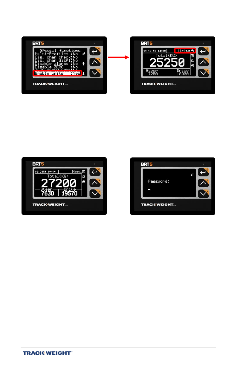
Enable units: Allows pounds to be selected as the unit of measurement.
Dis. verif prnt.: Disables the check which makes it impossible to print
during a calibration.
Simul Prn Detect: Allows to set up the printer header despite its
absence.
Password: Requests password when accessing the Menu.
Note: The default password is: 1 - 0 - 0 - 2.
Note: To change the default password, select “Enter Password” and
press ↵.
Password Max. len: Determines the password length, between 4 and 8
characters.
BRT 5 – User Manual | V1.2.007 | 36
Page 37
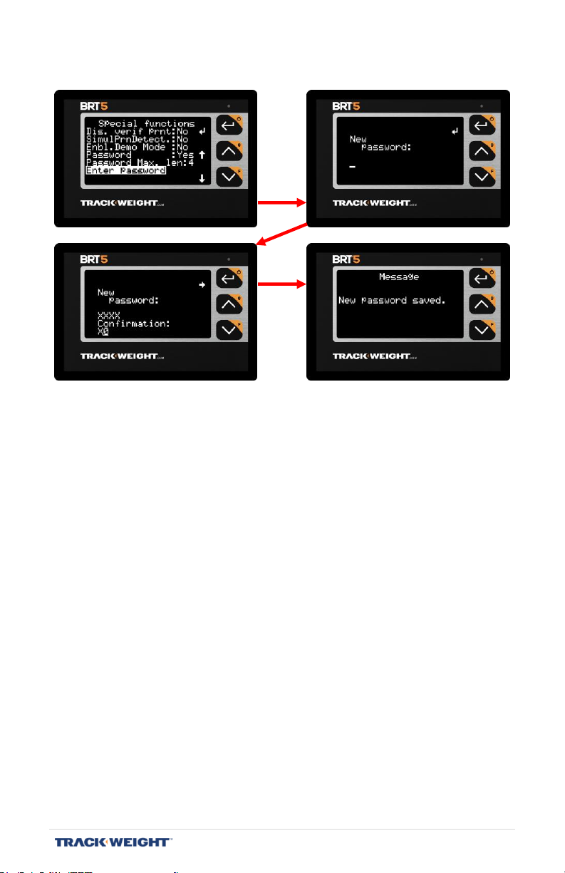
Enter Password: Allows configuration of a new password.
BRT 5 – User Manual | V1.2.007 | 37
Page 38

CALIBRATION
MENU> CALIBRATION
Before calibrating, make sure that:
a) Take note of the condition of the truck (level of fuel tanks,
cleanliness, weather conditions - since they may affect the
calibration);
b) The truck remains on a certified scale during data entry;
c) The numbers (weight) in the monitor are stable;
d) The wheels of the truck are straight;
e) The transmission is in neutral position;
f) The brakes are released;
g) The lift axle is lowered throughout the duration of the calibration
(12 wheels only);
h) The trailer lift axle is raised throughout the duration of the
calibration (semi-trailer);
i) Absence of sensor in error (that it does not have the message
"Sensor in error" scrolling at the top left of the screen);
j) The truck is empty during the empty calibration;
k) The truck is full during the full calibration.
The calibration process consists of:
1. Measuring and entering the weight of each axle group when the
truck is empty;
2. Loading the vehicle;
3. Measuring and entering the weight of each axle group when the
truck is full.
BRT 5 – User Manual | V1.2.007 | 38
Page 39
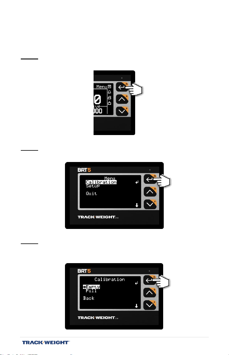
Empty Calibration
VERY IMPORTANT: Make sure the truck is empty.
Step 1
Press Menu.
Step 2
Select Calibration and press ↵.
Step 3
Select Empty and press ↵.
Note: To perform the Full load truck calibration, go to step 11.
BRT 5 – User Manual | V1.2.007 | 39
Page 40
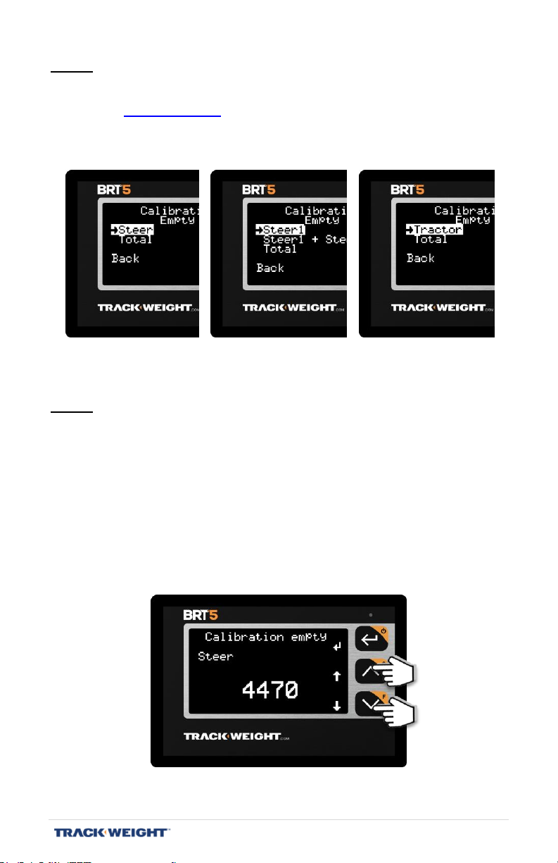
Step 4
Note: The choice of axle groups available depends on the type of truck selected.
Select the first axle group and press ↵.
(6 -10 -12 Wheels) (12 W 2 St) (Semi-trailer)
Step 5
See “Truck types”, p. 13.
Using the arrows, adjust the weight to the value indicated by the certified
scale.
Note: The weight must correspond to the requested axle group. For
example, for a “10 Wheels” type of truck, the “Front” axle group is
the axle connected to the vehicle’s front wheels. In this case,
position the truck so that the rear wheels are about 2 ft. from the
certified scale and take note of the position, as you will have to
reposition the truck in the same way for the full.
BRT 5 – User Manual | V1.2.007 | 40
Page 41
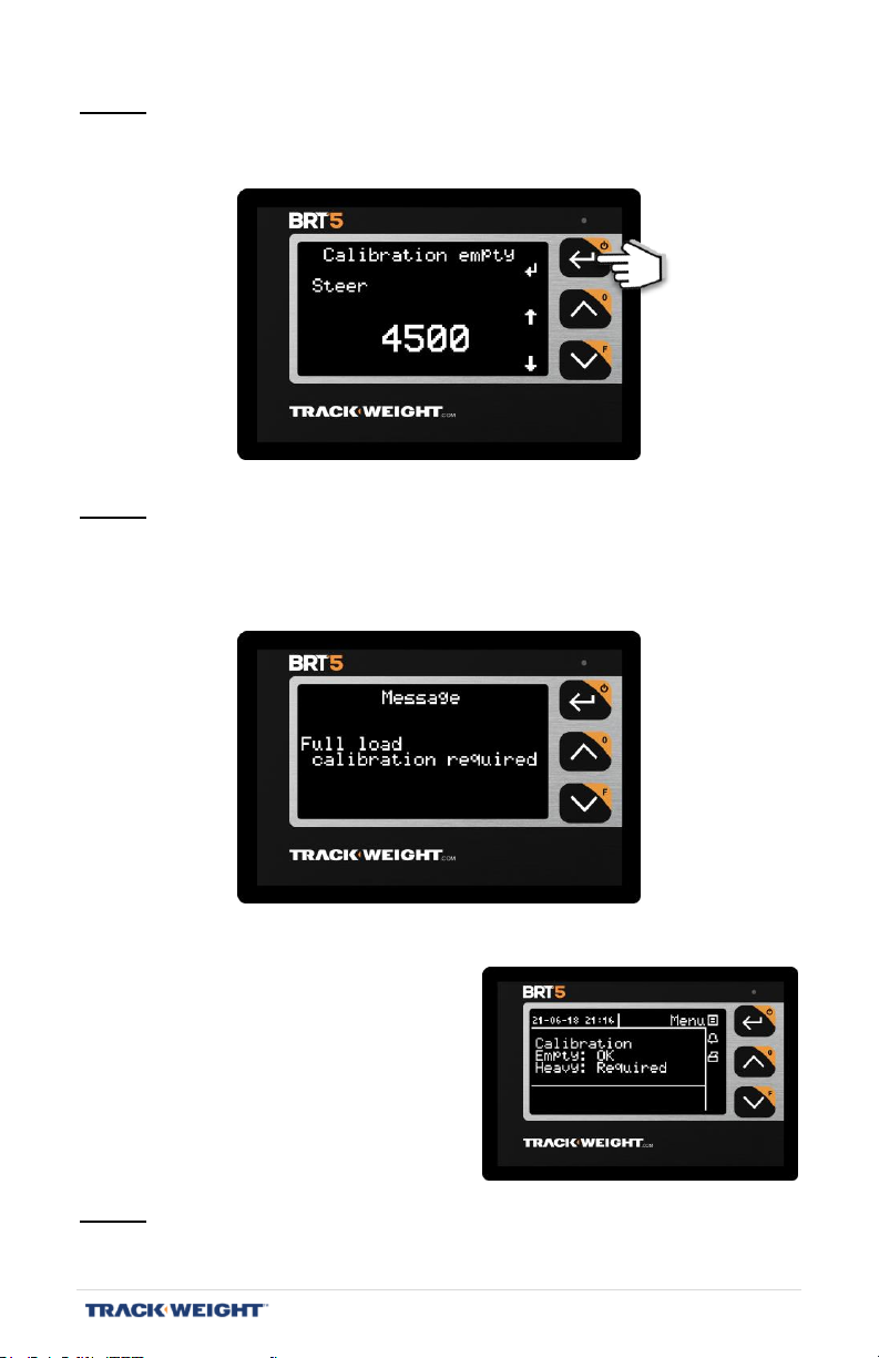
Step 6
Press ↵ to confirm.
Step 7
Repeat steps 4 to 6 for each available axle group in order. When “Total”
step is completed, the following message will appear:
Note: If the scale has never been
calibrated before, the following
message will appear:
Step 8
Completely load the truck.
BRT 5 – User Manual | V1.2.007 | 41
Page 42
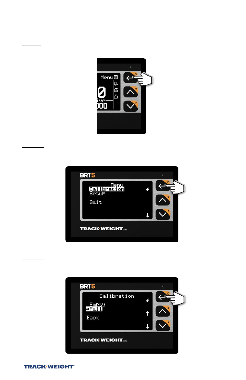
Full Load Calibration
Step 9
Press Menu.
Step 10
Select Calibration and press ↵.
Step 11
Select Full and press ↵.
Note: To perform the Empty truck calibration, return to step 3.
BRT 5 – User Manual | V1.2.007 | 42
Page 43
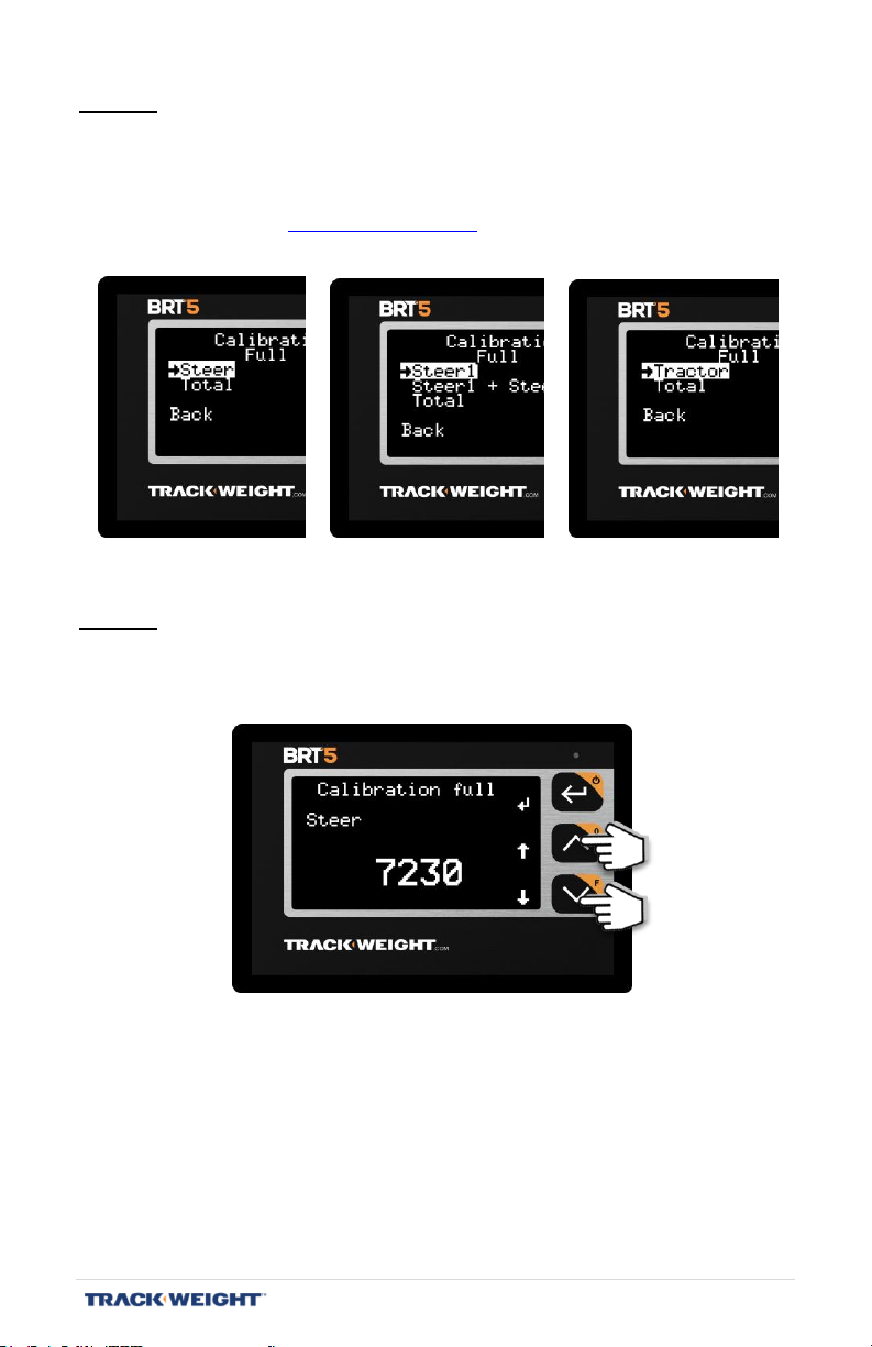
Step 12
Select the first axle group and press ↵.
Note: The choice of axle groups available depends on the type of truck
selected. See “Truck types”, p. 13.
(6-10-12 Wheels) (12W 2FR) (Semi-trailer)
Step 13
Using the arrows, adjust the weight to the value indicated by the certified
scale.
BRT 5 – User Manual | V1.2.007 | 43
Page 44
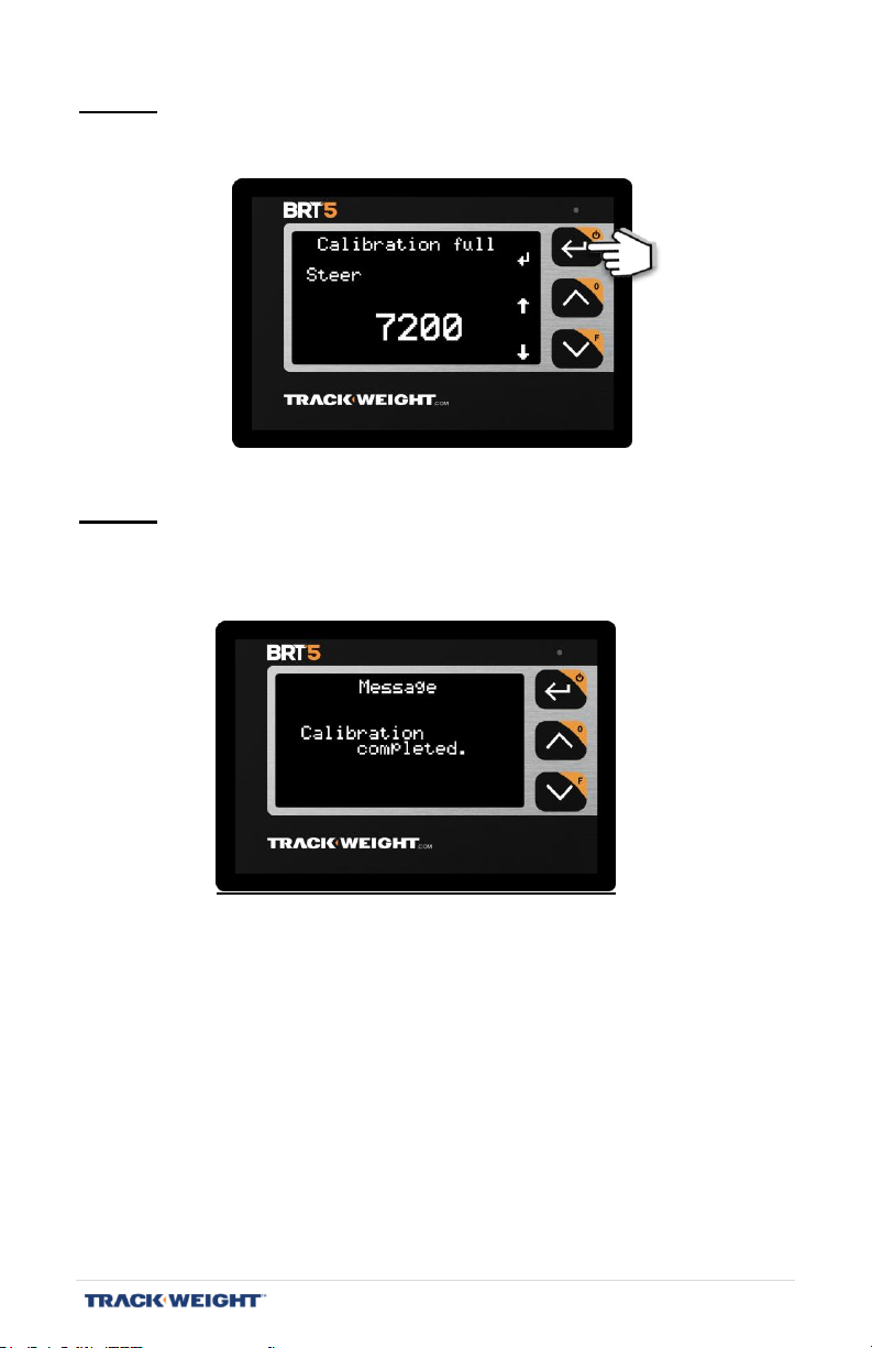
Step 14
Press ↵ to confirm.
Step 15
Repeat steps 12 to 14 for each available axle group in order. When the
“Total” step is completed, the following message will appear:
You are ready to work!
BRT 5 – User Manual | V1.2.007 | 44
Page 45
1
2
3
1
2
3
USE
SCALE FUNCTIONS
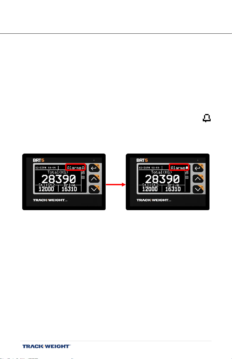
Alarms/ Lights
Enable/disable the alarms, external lights.
The alarms allow the loading equipment operator to know the loading
state at all times.
To activate the alarms:
- Press buttons 2 or 3 until the word and pictogram "Alarms”
appears at top right.
- Press Button 1. The pictogram will blink.
To disable the alarms:
- Press buttons 2 or 3 until the word and pictogram "Alarms”
appears at top right.
- Press Button 1. The pictogram will stop blinking.
BRT 5 – User Manual | V1.2.007 | 45
Page 46
1
2
3
1
2
3
1
2
3
1
2
3
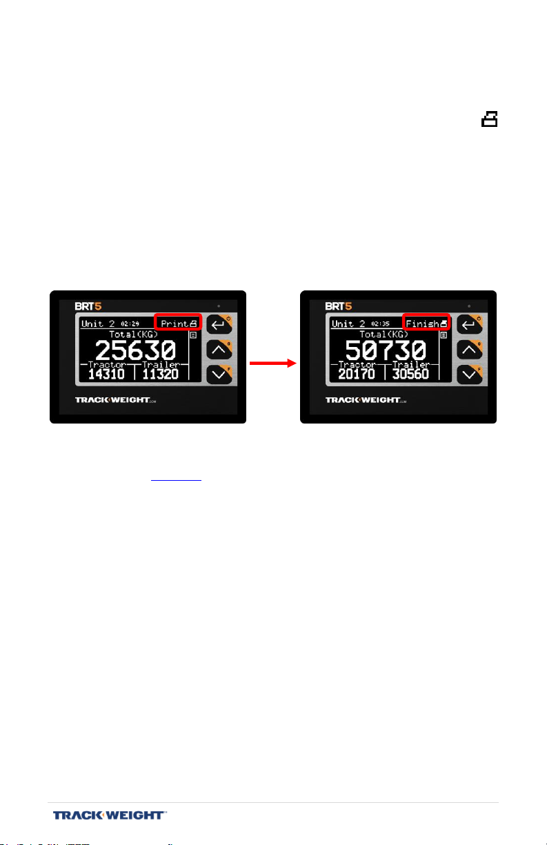
Printing
To print a ticket:
- Press Button 2 or 3 until the word and pictogram “Print”
appears at top right.
- Press Button 1 to start printing. The pictogram will blink to
indicate that the first part is printed.
- Once loading / unloading completed, press Button 1 again to
print the second part of the coupon. The pictogram will stop
blinking.
Note: Depending on the configuration, the ticket may be printed in one
part (see page 24). Therefore, the last step is not required.
BRT 5 – User Manual | V1.2.007 | 46
Page 47
1
2
3
1
2
3
1
2
3
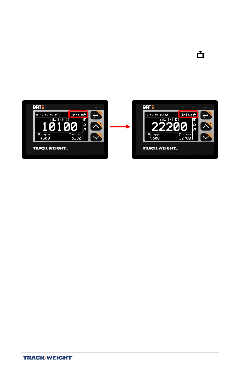
Units
To change the unit of measure used:
- Press Buttons 2 or 3 until the word and pictogram “Units”
appears at top right.
- Press Button 1 to change the unit of measure.
Note: The kilogram (kg) is the default unit of measurement.
BRT 5 – User Manual | V1.2.007 | 47
Page 48
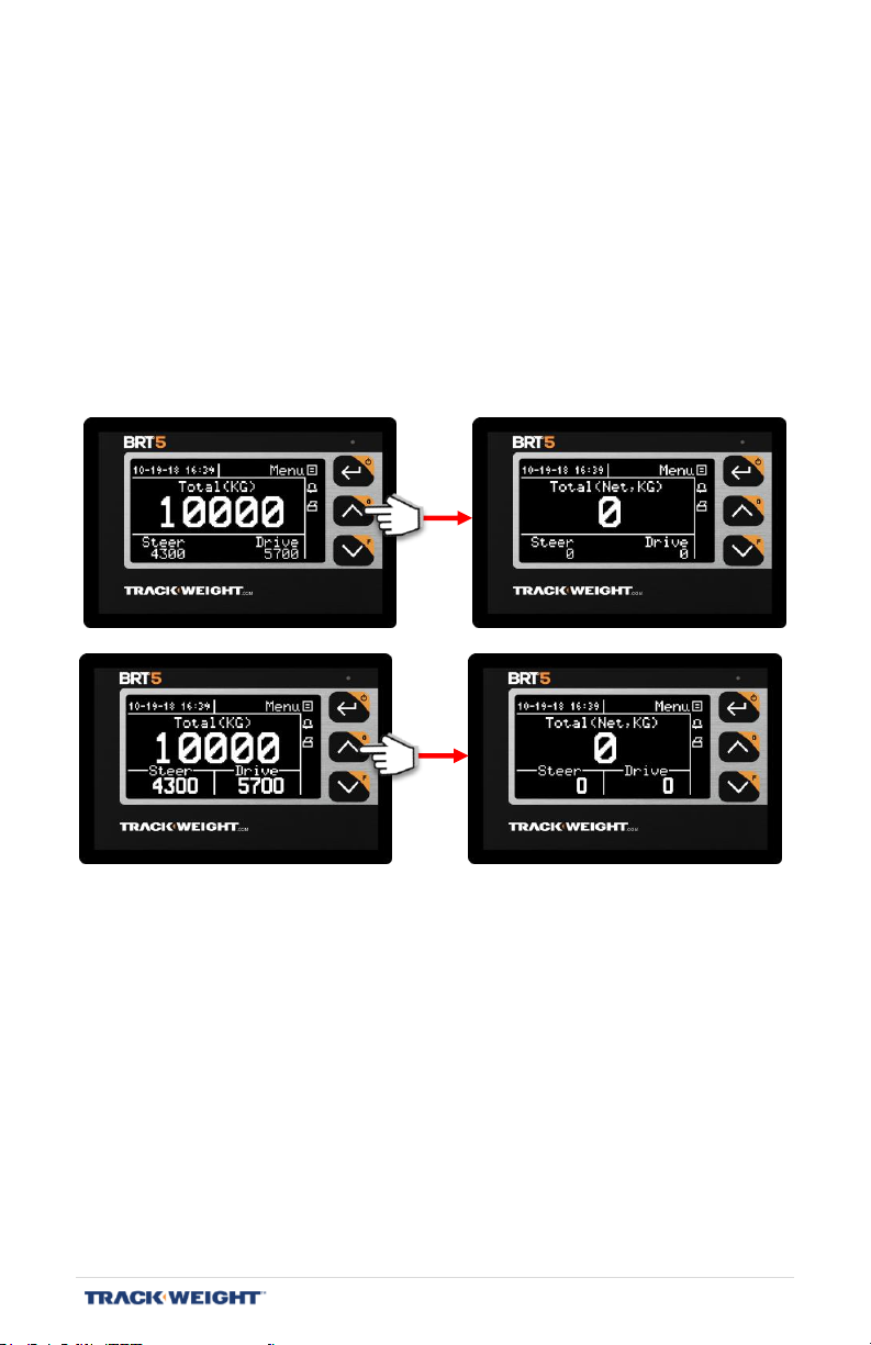
Zeroing
Enable/disable the zero function.
The zero function allows you to measure the net weight involved when
loading or unloading.
To enable the zero function:
- Hold Button 2 to activate zeroing.
To disable the zero function:
- Press Button 2 again to deactivate the zeroing.
BRT 5 – User Manual | V1.2.007 | 48
Page 49
Sensor type
Function
Minimum
Maximum
Unit
Air
Air 6 115
PSI
Angle
RT
-40.0
-15.0
mV
Load cell under the
fifth wheel
RT
-40.0
-26.0
mV
RT
RT
-28.0
-16.0
mV
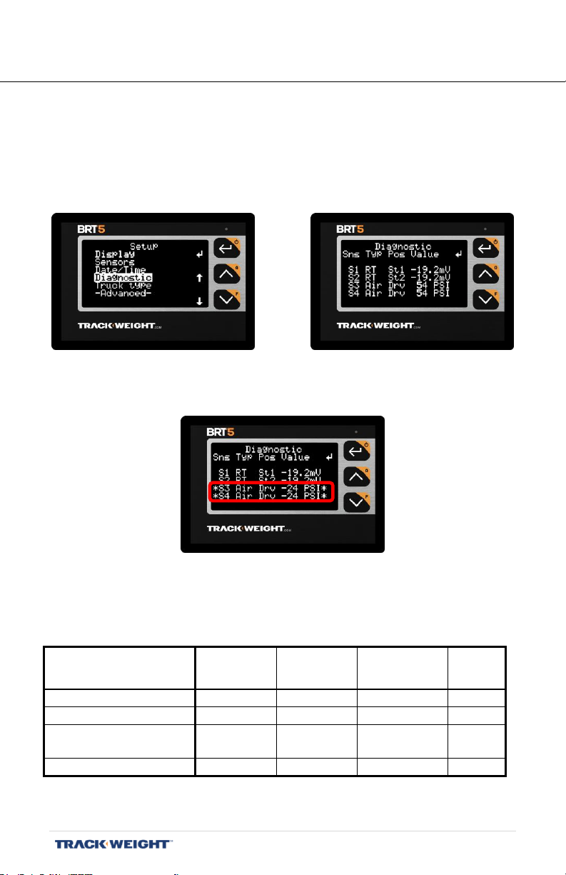
DIAGNOSTIC
MENU> SETUP> DIAGNOSTIC
Checking the sensors
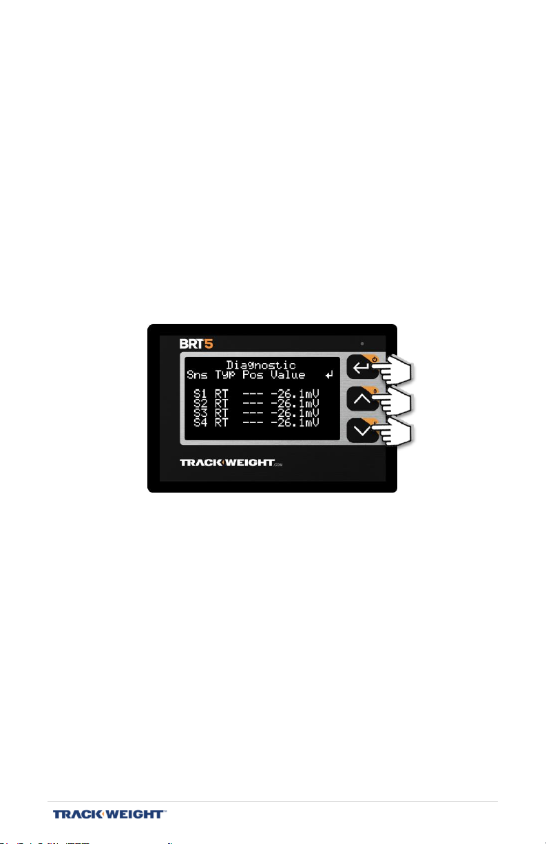
[Menu/Setup/Diagnostic]
View the data from all of the sensors connected to the system.
When one or more sensors are in error, asterisks will flash on each side
if the type and position of these have been defined.
Normal working ranges* are:
Table of working ranges depending on sensor type
* These numbers do not constitute the initial adjustment values.
BRT 5 – User Manual | V1.2.007 | 49
Page 50
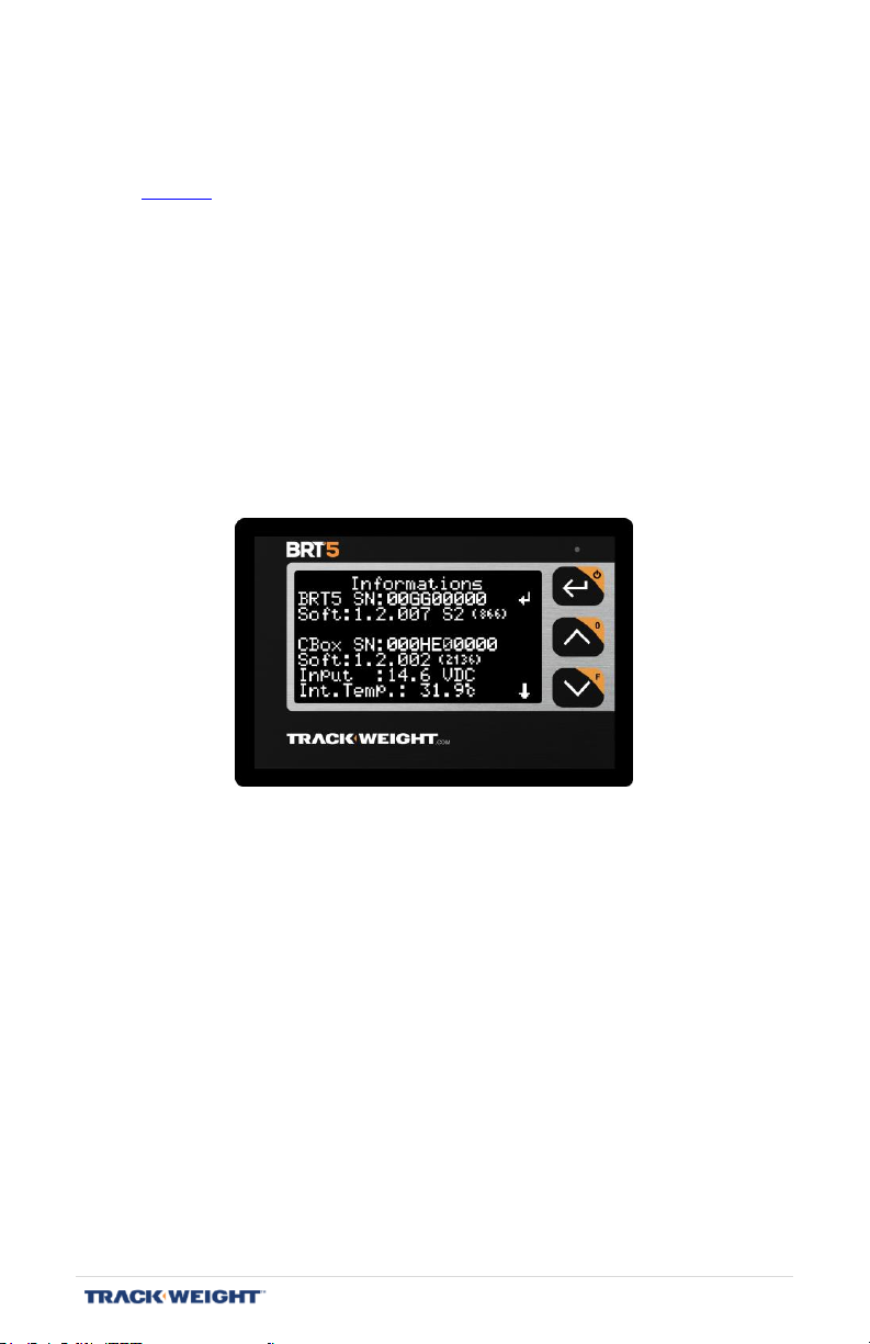
System information
[Menu/Setup/-Advanced-/Information]
Note: This menu only appears when the advanced functions are activated. See
page 29.
View various technical system information:
- BRT5 NS: monitor serial number
- Version: version of the monitor software
- CBox NS: serial number of the communication box
- Version: software version of the communication box
- Input: Voltage supply
- Internal T.: Internal temperature
- Brightness: Brightness captured
Note: This menu is also available when button 1 remains pressed a few
seconds to start the device.
BRT 5 – User Manual | V1.2.007 | 50
Page 51

MAINTENANCE
Repairing an axle equipped with an RT sensor
When mechanical maintenance requires an RT sensor to be removed:
- Remove the metal cover.
- Be sure to properly clean the RT sensor threads.
- Remove the RT sensor adjustment nut and the washers.
- Remove the positioning bolt and washer.
- Protect the sensor and the wire against any external
contamination, water, grease, solder, etc.
- Perform the scheduled mechanical maintenance.
- To avoid voiding the warranty, do not attempt to replace the RT
sensor.
- Contact your TrackWeight representative to reinstall the RT
sensor.
Cleaning the monitor
- Make sure the monitor is turned off.
- First, remove the dust from the surface.
- Dampen a cloth with water and mild soap.
- Use a soft dry cloth to remove the excess water.
- Avoid any contact with abrasive products.
Load cell under the fifth wheel
- Regularly replace the bushing.
- Regularly check the tightening torque of the mounting bolts.
- If a connector must be detached, make sure that both sides of it
are clean and dry before putting it back in place. DO NOT USE
GREASE on the connectors.
- Apply a layer of high quality spray paint to prevent corrosion.
Make sure that the assembly is complete and that the connector
is firmly attached before applying the paint.
- Apply a lubricant to the bearing surface of the load cell using the
grease fitting on the side of the fifth wheel. The fifth wheel must
be slightly raised to enable the lubricant to spread efficiently.
- See the product-specific documentation.
Air line maintenance
- Ensure that the air dryer is functional.
- Check for condensation in the air line and vent if necessary.
BRT 5 – User Manual | V1.2.007 | 51
Page 52

SPECIFICATIONS
BRT 5 Monitor
Screen FSTN. Character height of 4 to 12 mm
Dimensions 11.1 cm x 7.5 cm x 2.5 cm
Operating temperature -20 °C to 70 °C
Resolution 10, 50, 100, in KG or LB
Voltage 8.0 V/DC 0.9W
Weight 132 g
Part Number BRT06100
Communication box
Dimensions 15 cm x 11 cm x 4 cm
Operating temperature -40 °C to 85 °C
Voltage 12-32 V/DC 2.4W
Ports 2x RS-232, 3x Alarms outputs, 1x
CANBUS, 1x USB, 4x Sensors inputs,
2x Auxiliary inputs
Sensor types RT – Air – Load Cell – Angle
Weight 288 g
Part Number BRT06500
BRT 5 – User Manual | V1.2.007 | 52
Page 53

LIST OF PARTS
Display
BRT06100 BRT 5 Monitor
BRT 6319 BRT 5 Support
BRT 6136 2M Monitor Cable
Communication Box
BRT06500 Communication Box
BRT 6137 Power Cable
RT Sensor
BRT 550M-XX RT mechanical sensor & assembled connector
BRT 550-XX RT Mechanical sensor without connector
BRT 5419P Sensor connector kit
BRT 600 Block kit for sensor installation
BRT 5110 Sensor installation insulation
BRT 5699 Cover & hardware
Air Sensor
BRT 560 Air sensor
Light options
BRT 620-M Kit with 2 LED lights
BRT 5381 Support for 2 LED lights
BRT 622 Kit with 3 LED lights
BRT 5382 Support for 3 LED lights
Printer options
BRT 504 Printer Set
BRT 5324 Printer
BRT 6313 RJ45 Cable for printer
BRT 5462 Printer Roll
Load cell options
BRT 5528 Load cell under the fifth wheel
BRT 5390 36’ load cell cable
BRT 5529 Load cell mounting
BRT 5371 3/4” Load cell plate
Semi-trailer installation options
BRT 580 Helical Installation kit - Main tractor side service
BRT 582 Right installation kit, 3/8"hose - Main tractor-side service
BRT 584 Installation kit - Main trailer side valve
BRT 5 – User Manual | V1.2.007 | 53
Page 54
TECHNICAL SUPPORT
Instructions on the main screen
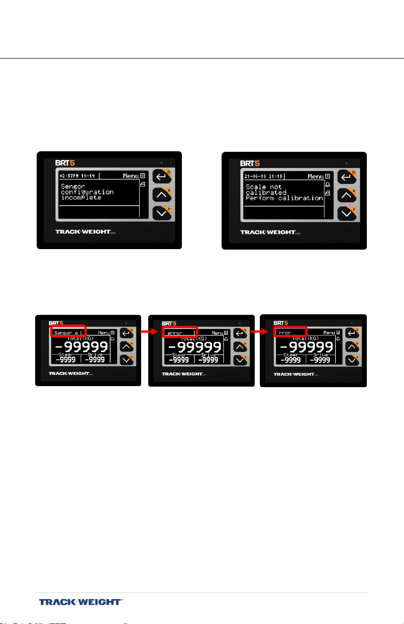
If the scale has never been calibrated, messages may appear all over
the main screen:
If the scale has already been calibrated, the messages will scroll to the
top left of the main screen:
The possible messages to appear:
- Calibration required
- Calibration in progress
- Sensor in error
- Check sensor configuration
Unusually high variation:
- Moving truck.
- Sensor error
BRT 5 – User Manual | V1.2.007 | 54
Page 55

LIMITED WARRANTY
TrackWeight Systems Inc. (“TrackWeight”) guarantees that at the time the BRT4 and BRT5
scale(s) (the “Equipment”) are delivered to the buyer, they are not, to TrackWeight’s
knowledge, defective in their design and that they conform to the specifications contained
in the TrackWeight documentation. For a period of three (3) years after delivery of the
Equipment (“Warranty Period”), TrackWeight agrees to repair the Equipment or have it
repaired at no cost to the buyer, subject to the following conditions:
1. TrackWeight shall not provide any other express or implied warranty (including
any warranties of merchantability or of suitability for an intended purpose or noninfringement) on the Equipment unless explicitly stated in writing herein or in the
order confirmation.
2. Within the Warranty Period, TrackWeight reserves the right, at its sole discretion,
to replace or repair defective parts or to credit the buyer for the corresponding
value.
3. The warranty does not cover transportation costs, travel allowance, etc. for the
return of the defective Equipment to the TrackWeight warehouse or its authorized
distributor. Once replaced or repaired, the Equipment will be returned to the
buyer at the buyer’s expense.
4. This warranty is not transferable and applies only to the original buyer.
5. In case of defective or non-compliant equipment, the buyer must immediately
communicate this defect or non-compliance to TrackWeight and provide
TrackWeight with all of the available information which could be used to evaluate
the defects and their origins.
6. Only the original buyer may request a service covered by the warranty. This
person must provide TrackWeight with proof of purchase for the Equipment;
7. For the warranty to remain valid, the Equipment must be installed according to
instructions in the instruction booklet included with each unit.
8. The Equipment must not have been previously modified or repaired by anyone
other than an TrackWeight authorized technician;
9. The Equipment must not have been visibly damaged, negligently or improperly
handled, or used or installed contrary to the instructions contained in the
instruction booklet included with the Equipment. TrackWeight’s opinion in these
matters will be considered final and binding on the buyer.
10. The warranty does not cover the normal wear of the Equipment.
11. The warranty does not cover damage caused by lightning, water or other natural
causes.
12. For the warranty to apply, the Equipment returned must have the original
Equipment label with the serial number. If the label has been removed or
modified, the warranty will automatically be void.
13. The warranty offered by TrackWeight only covers the cost of repairing or
replacing the Equipment. It does not cover the inconvenience, loss of time, or
resulting losses or damages. Specifically, the only remedy available to the
BRT 5 – User Manual | V1.2.007 | 55
Page 56

purchaser, regarding the present warranty, is limited, at TrackWeight’s discretion,
to the replacement or repair of the Equipment or to a credit corresponding to its
value during the Warranty Period. The buyer cannot claim any other remedy.
14. The Equipment repaired or replaced under the present terms will be under
PROCEDURE FOR WARRANTY RELATED RETURNS
When a defect in the Equipment is detected, the following procedure must be followed for
the warranty to remain in force:
In the event that TrackWeight reasonably determines that the Equipment and parts were
returned in an unacceptable condition for the Equipment’s type of use, TrackWeight
reserves the right to refuse to repair the Equipment and to return it at the buyer’s expense.
warranty for the remainder of the Warranty Period.
15. Instructions for the required Equipment calibration or adjustments are included in
the instruction booklet provided upon purchase. Calibration and adjustments are
not covered by the warranty. The buyer must install the Equipment, or have it
installed at the buyer’s own expense, by a qualified person and in accordance
with TrackWeight’s recommendations and instructions. It is understood that the
buyer assumes sole responsibility for the Equipment installation and holds
TrackWeight harmless from any liability or damages arising therefrom unless the
buyer demonstrates compliance with the specifications contained in
TrackWeight’s documentation.
Contact the local dealer where you purchased the Equipment and provide your
invoice number and the serial number of your monitor or black box.
Once the return has been approved, if applicable, TrackWeight or the authorized
distributor will provide you with a return authorization number allowing you to
return the Equipment for a warranty evaluation by a TrackWeight authorized
technician. In such circumstances, TrackWeight is entitled to a reasonable
verification period to perform the necessary tests.
For returns made by mail or through a shipping service, be sure to include every
defective part with the Equipment and a copy of your purchase invoice with the
return authorization number.
Upon return, the Equipment must be clean and carefully packaged to prevent
further damage during shipping. TrackWeight is not responsible for damages
caused during the transport of the Equipment.
You must pay the transportation costs for the return of the Equipment and the
related parts, including customs and brokerage fees, if any.
BRT 5 – User Manual | V1.2.007 | 56
Page 57
Date:
Axle
Group
Empty weight
Full weight
Notes
1
2 3 4 5
Date:
Axle
Group
Empty weight
Full weight
Notes
1
2 3 4 5
Date:
Axle
Group
Empty weight
Full weight
Notes
1
2 3 4 5
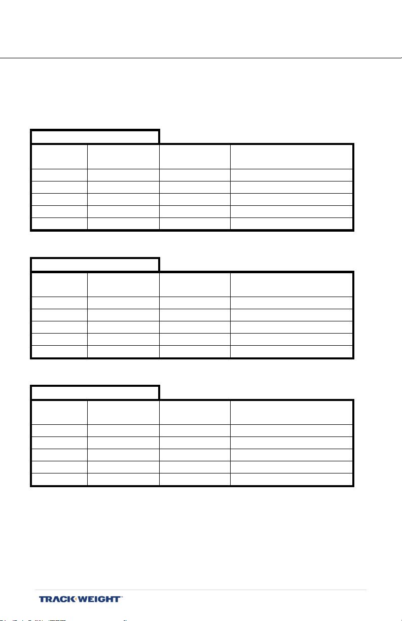
CALIBRATION SHEET
Truck/Tractor: ____________
Year: ____________
Unit: ____________
BRT 5 – User Manual | V1.2.007 | 57
Page 58

CONTACT US
This manual has been produced to standardize the configuration and
calibration of the TrackWeight BRT 5 onboard weighing system and
related optional accessories.
If you have any questions during setup and/or calibration, please contact
your authorized TrackWeight dealer or call us at 1-800-648-8132.
TrackWeight Systems Inc
30 Emilien-Marcoux, Suite 101
Blainville, QC, Canada J7C 0B5
Toll Free : 1-800-648-8132
www,trackweight.com
[email protected]
Business hours
Monday to Friday
8 am to 5 pm (Eastern Canada)
TrackWeight products, RT Sensors, BRT 4 and BRT 5 are the property
of TrackWeight Systems Inc.
All rights reserved 2018. V1.0.004
BRT 5 – User Manual | V1.2.007 | 58
Page 59

UPDATE NOTES
V1.2.007 (BRT06331.1 User Manual EN TrackWeight BRT5):
- Updating of screens
- Added the Startup screen with details
- Added "Date / Time" configuration
- Added "Communication" section
- Update of the "System Information" section
BRT 5 – User Manual | V1.2.007 | 59
Page 60

Onboard truck and semi-trailer scales manufacturer
DESIGN AND
MADE IN
CANADA
 Loading...