

Page 1

Special Analog Controller
ENABLE
standby
random
value
pause
program audio
intensity rate
bump
User Guide
High End Systems, Inc.
2217 West Braker Lane
Austin, TX 78758 U.S.A.
Part No. 60600033
Page 2

User Guide
V ersion 1.0, June 1993
© Lightwave Research, Inc. 1993, All Rights Reserved
i
Page 3

Trackspot® Special Analog Controller
Contents
Introduction
...............................................................................................1
Section I
Master/Slave Mode
Setup...................................................................................................1
Boot-up ...............................................................................................2
.................................................................................1
Section II
LED Indicators and Associated Keys
Enable.................................... .............................................................2
Standby.................................. .............................................................3
Program........................................................ ..................................... 3
Automatic Program Step.....................................................................3
Intensity...............................................................................................3
Rate ....................................................................................................3
Audio...................................................................................................3
Random ..............................................................................................3
Pause .................................................................................................4
............................................2
Section III
Non-Illuminated Keys
Arrow “up”.......................................................................................... 4
Arrow “down”...................................................................................... 4
Bump...................................................................................................4
Section IV
Supllemental Features
EPROM Version/LED Test....................................... ...........................4
Special Modes ....................................................................................4
Rate ....................................................................................................4
Audio.................................................................................................. 5
ii
...........................................................................4
.................................................... .................... 4
Page 4

Section V
W arranty Procedures
Saving the Shipping Materials ............................................................5
Limited Warranty................................................................................ 5
Returning an Item Under Warranty for Repair................................... 5
....................................................... .....................5
Getting Help
High End Systems Service provides a help line should you encounter problems
during your in sta lla tio n or initial oper ati on. C urren tly, service hours are 8 a.m . to 6
p.m. (Central), Monday through Friday. The numb ers are:
Telephone: (800) 890-8989
24 hour Fax: (512) 834-9195
24 hour voice mail: (512) 837-3053
or (800) 890-8989
Special Analog Controller 1
Page 5
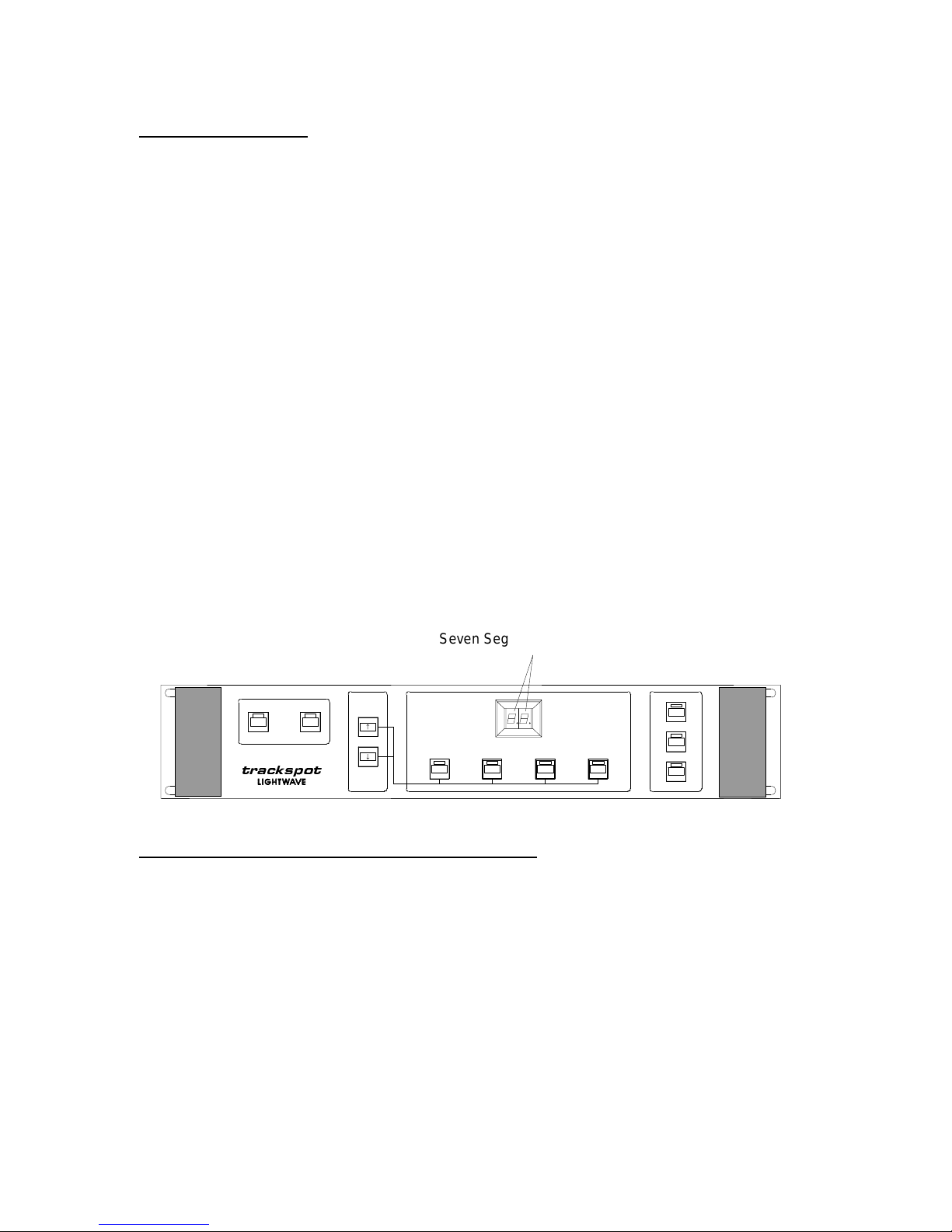
Introduction
The
trackspot
Special Analog Controller is equipped with features that enable you to interact with the
fixture. It provides you with the ability to access and manipulate the 32 programs stored in the
EPROM.
The Special Analog Controller features include
• Self powered (from
trackspot
Master)
:
• Controls Master fixture
• Accesses 32 preset programs
• Fixture homing upon enable
• LED output monitors
• Seven segment display (SSD) LED’s
• Fixture remote enable/disable
• Standby
• Program select
• Program scroll
• Automatic program step
• Master intensity control
• Program step rate
• Audio program advance rates
• Random step change
• Mirror pause
• Value control (up and down arrows)
• EPROM version/LED test
• Special rate and audio modes
trackspot
Seven Segment Display LEDs
ENABLE
standby
value
program audio
intensity rate
random
pause
bump
Section I: Master/Slave Mode
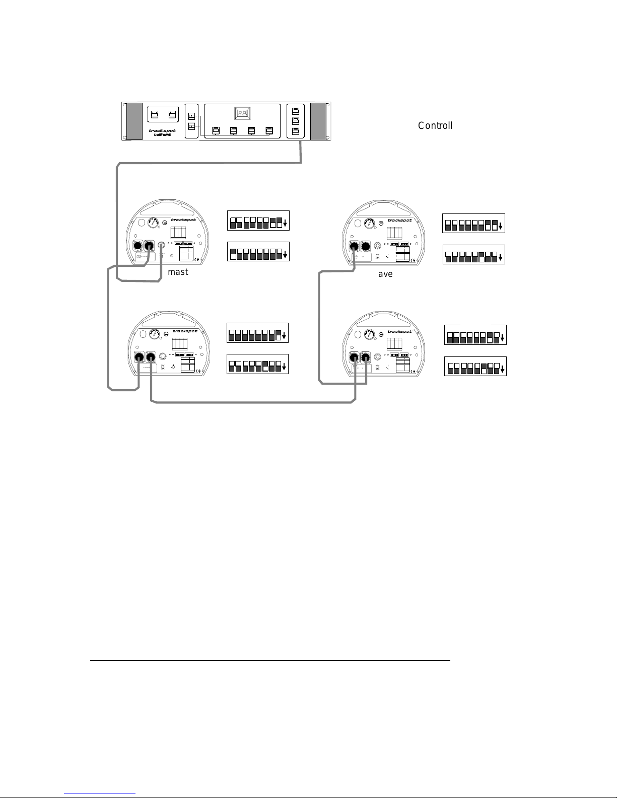
The Special Analog Controller is connected to the selected Master fixture through an 8-pin DIN connector
cable. Once connected, the controller may be used to access
trackspot’s
Setup
When the Master fixture is plugged in and its
personality
connector supplies unregulated 24 volts DC to the controller.
• Make sure the Master fixture is unplugged.
• Use a 24 AWG, 150 ft. (maximum) 8-pin DIN shielded cable to connect the controller to the Master
fixture.
• Use 3-pin XLR, two-conductor data cables to connect the Master and Slaves in the Daisy Chain
method (see Example 1.A, page 2).
• Turn the Master fixture
personality
switch eight on, and set the
total units (including the Master).
The Special Analog Controller must be connected to the Master fixture (
Note:
operate. If switch eight is off, the controller will not receive the necessary voltage to work.
• Turn the Slave fixtures
personality
switch three on, and set each Slave’s
sequential order of each unit.
switch eight is on, pin one of the 8-pin DIN
32 preset programs.
address
switch to equal the number of
address
personality
switch to the
eight on) to
2 Special Analog Controller
Page 6
Example 1.A
WARNING: CHANGE VOLTAGE SELECT ONLY WITH POWER REMOVED.
CAUTION: HOT REMOVE POWER BEFORE RELAMPING
WARNING: NOT FOR RESIDENTIAL USE. TO REDUCE THE RISK OF
FIRE OR ELECTRI C SHOCK, DO NOT EXPOSE TO RAIN OR MOISTURE ,
NO USER SERVICEABLE PARTS INSIDE. REFER SERVICING TO
QUALIFIED SERVICE PERSONNEL. FOR SAFE OPERATION CONSULT
USER MANUAL.
MODEL
SERIAL
FACTORY SET VA C
WATTS HZ
DATE QC
WARNING: CHANGE VOLTAGE SELECT ONLY WITH POWER REMOVED.
CAUTION: HOT REMOVE POWER BEFORE RELAMPING
WARNING: NOT FOR RESIDENTIAL USE. TO REDUCE THE RISK OF
FIRE OR ELECTRI C SHOCK, DO NOT EXPOSE TO RAIN OR MOISTURE ,
NO USER SERVICEABLE PARTS INSIDE. REFER SERVICING TO
QUALIFIED SERVICE PERSONNEL. FOR SAFE OPERATION CONSULT
USER MANUAL.
MODEL
SERIAL
FACTORY SET VA C
WATTS HZ
DATE QC
ENABLE
FUSE
VOLTAGE SELECT
DATA OUTDATA IN
ANALOG IN
0-10V
ANALOG
GND
TILT
COLOR
5
42
MSPEED
3761
PAN
8
GOBO DIM
SHUTTER
VOLTAGE SELECT
DATA OUTDATA IN
ANALOG IN
0-10V
ANALOG
GND
TILT
5
42
3761
MSPEED
8
GOBO DIM
SHUTTER
slave 1
standb y
LIGHTWAVE RESEARCH
2209 WEST BRAKER LANE, AUSTIN, TEXAS U.S.A.
SWITCHESONSWITCHESADDRESS ADDRESS
ON
3,413
none01
1,3,414
102
2,3,415
203
1,2,3,416
1,204
517
305
1,518
1,306
2,519
2,307
1,2,520
1,2,308
3,521
409
1,3,522
1,410
2,3,523
2,411
1,2,3,524
1,2,412
FOR FURTHER INFORMATION
PLEASE CONSULT USER MANUAL
PERSONA LITY
ADDRESSENABL EFAN
PERSONALI TY
FIXTURE MODE SWITCHES 1-2
NORMAL RUN
SELF TEST
SET-UP
SPECIAL ANALOG
LAMP SAVE
INPUT
CONTROL MODE SWITCHES 3-8
GND
LIGHTWAVE CON TROL
DMX 1-256
DMX 257-512
2
4
5
24 VDC
ANALOG
OUT
1
3
8
AUDIO (SLAVE)
6 7
(UNREG.)
AUDIO (MASTER )
PAN INVERT
TILT INVERT
FOR FUTHER INFORMATION
FOR FURTHER INFORMATION
CONSULT USERS MANUAL
PLEASE CO NSULT USER MANUAL
master
fixture
LIGHTWAVE RESEARCH
2209 WEST BRAKER LANE, AUSTIN, TEXAS U.S.A.
SWITCHESONSWITCHESADDRESS ADDRESS
FUSE
ON
3,413
none01
1,3,414
102
2,3,415
203
1,2,3,416
1,204
517
305
1,518
1,306
2,519
2,307
1,2,520
1,2,308
3,521
409
1,3,522
1,410
2,3,523
2,411
1,2,3,524
1,2,412
FOR FURTHER INFORMATION
PLEASE CONSULT USER MANUAL
ADDRESSENABLEFA N
PERSONALI TY
FIXTURE MODE SWITCHES 1-2
NORMAL RUN
SELF TEST
SET-UP
SPECIAL ANALOG
LAMP SAVE
INPUT
CONTROL MODE SWITCHES 3-8
GND
LIGHTWAVE CON TROL
COLOR
DMX 1-256
DMX 257-512
2
4
5
24 VDC
ANALOG
1
3
OUT
PAN
8
AUDIO (SLAVE)
6 7
(UNREG.)
AUDIO (MASTER )
PAN INVERT
TILT INVERT
FOR FUTHER INFORMATION
FOR FURTHER INFORMATION
CONSULT USERS MANUAL
PLEASE CO NSULT USER MANUAL
value
®
AUDIO MIC
SWITCHES
ON
NONE
1
2
1,2
NONE
5
4
4,5
3
8
6
7
®
PERSONA LITY
AUDIO MIC
SWITCHES
ON
NONE
1
2
1,2
NONE
5
4
4,5
3
8
6
7
program audio
intensity rate
ADDRESS
8 7 6 5 4 3 2 1
PERSONALITY
8 7 6 5 4 3 2 1
ADDRESS
8 7 6 5 4 3 2 1
PERSONALITY
8 7 6 5 4 3 2 1
random
pause
bump
on
on
8-Pin DIN Connected To
Special Analog Controll er
8 7 6 5 4 3 2 1
PERSONALITY
8 7 6 5 4 3 2 1
WARNING: CHANGE VOLTAGE SELECT ONLY WITH POWER REMOVED.
CAUTION: HOT REMOVE POWER BEFORE RELAMPING
WARNING: NOT FOR RESIDENTIAL USE. TO REDUCE THE RISK OF
FIRE OR ELECTRI C SHOCK, DO NOT EXPOSE TO RAIN OR MOISTURE ,
NO USER SERVICEABLE PARTS INSIDE. REFER SERVICING TO
QUALIFIED SERVICE PERSONNEL. FOR SAFE OPERATION CONSULT
USER MANUAL.
MODEL
SERIAL
FACTORY SET VA C
WATTS HZ
DATE QC
VOLTAGE SELECT
DATA OUTDATA IN
1,3,414
102
2,3,415
203
1,2,3,416
1,204
517
305
1,518
1,306
2,519
2,307
1,2,520
1,2,308
3,521
409
1,3,522
1,410
2,3,523
2,411
1,2,3,524
1,2,412
FOR FURTHER INFORMATION
PLEASE CONSULT USER MANUAL
ANALOG IN
0-10V
ANALOG
GND
TILT
2
5
4
3761
MSPEED
8
GOBO DIM
SHUTTER
AUDIO MICPERSONA LITYADDRESSENABL EFAN
PERSONALI TY SWITCHES
ON
FIXTURE MODE SWITCHES 1-2
NORMAL RUN
NONE
SELF TEST
1
SET-UP
2
SPECIAL ANALOG
LAMP SAVE
1,2
INPUT
CONTROL MODE SWITCHES 3-8
GND
LIGHTWAVE CON TROL
NONE
COLOR
DMX 1-256
5
DMX 257-512
4
2
24 VDC
4
5
ANALOG
4,5
1
3
OUT
PAN
8
AUDIO (SLAVE)
3
6 7
(UNREG.)
AUDIO (MASTER )
8
PAN INVERT
6
TILT INVERT
7
FOR FUTHER INFORMATION
FOR FURTHER INFORMATION
CONSULT USERS MANUAL
PLEASE CO NSULT USER MANUAL
®
LIGHTWAVE RESEARCH
2209 WEST BRAKER LANE, AUSTIN, TEXAS U.S.A.
SWITCHESONSWITCHESADDRESS ADDRESS
FUSE
ON
3,413
none01
ADDRESS
on
on
slave 3
on
FUSE
VOLTAGE SELECT
WARNING: CHANGE VOLTAGE SELECT ONLY WITH POWER REMOVED.
CAUTION: HOT REMOVE POWER BEFORE RELAMPING
WARNING: NOT FOR RESIDENTIAL USE. TO REDUCE THE RISK OF
FIRE OR ELECTRI C SHOCK, DO NOT EXPOSE TO RAIN OR MOISTURE ,
NO USER SERVICEABLE PARTS INSIDE. REFER SERVICING TO
QUALIFIED SERVICE PERSONNEL. FOR SAFE OPERATION CONSULT
USER MANUAL.
DATA OUTDATA IN
on
MODEL
SERIAL
FACTORY SET VA C
WATTS HZ
DATE QC
ANALOG IN
0-10V
ANALOG
GND
TILT
COLOR
2
5
4
3761
MSPEED
PAN
8
GOBO DIM
SHUTTER
LIGHTWAVE RESEARCH
2209 WEST BRAKER LANE, AUSTIN, TEXAS U.S.A.
SWITCHESONSWITCHESADDRESS ADDRESS
ON
none01
102
203
1,204
305
1,306
2,307
1,2,308
409
1,410
2,411
1,2,412
FOR FURTHER INFORMATION
PLEASE CONSULT USER MANUAL
SPECIAL ANALOG
INPUT
GND
2
24 VDC
4
5
1673
OUT
8
(UNREG.)
FOR FUTHER INFORMATION
CONSULT USERS MANUAL
3,413
1,3,414
2,3,415
1,2,3,416
517
1,518
2,519
1,2,520
3,521
1,3,522
2,3,523
1,2,3,524
PERSONALI TYSWITCHES
FIXTURE MODE SWITCHES 1-2
NORMAL RUN
SELF TEST
SET-UP
LAMP SAVE
CONTROL MODE SWITCHES 3-8
LIGHTWAVE CON TROL
DMX 1-256
DMX 257-512
ANALOG
AUDIO (SLAVE)
AUDIO (MASTER )
PAN INVERT
TILT INVERT
FOR FURTHER INFORMATION
PLEASE CO NSULT USER MANUAL
®
AUDIO MICPERSONA LITYADDRESSENABL EFAN
ON
NONE
1
2
1,2
NONE
5
4
4,5
3
8
6
7
ADDRESS
8 7 6 5 4 3 2 1
PERSONALITY
8 7 6 5 4 3 2 1
on
on
slave 2
Boot-up
The Special Analog Controller draws its power from the selected Master fixture. It receives unregulated 24
volts DC from the Master fixture through a single eight-conductor low voltage cable. When the Master
fixture is on and its
personal ity
switc h e igh t i s i n th e on p os i ti o n, th e c o nt r oller is on, even t ho u gh al l fr ont
panel LED’s are off.
•The controller appears “off” when the Master fixture is first plugged in (
personality
switch eight on), or
when the controller is disabled. All LED’s are off. However, at this time the controller is active and
monitoring the Enable key, waiting to be booted up.
• When you press the Enable key, you will see the boot-up routine. The Enable LED illuminates, the
Standby LED flashes, and the Seven Segment Display (SSD) LED’s show three horizontal bars.
• During this time, the controller is initializing the Master fixture. When the Master fixture has homed, it will
cause all Slave fixtures to home.
• After homing, the Enable, Standby, and Program LED’s remain illuminated, while the Rate LED flashes,
and the Seven Segment Display LED’s show 01. This indicates that the controller is enabled and in the
standby mode.
• The flashing Rate LED signals that the controller will use time as a trigger for the next page of the
selected program.
• The default values at start-up are; Program one, Rate at level three and active, and Audio at level three
and inact ive.
You may check this by pushing the associated keys.
Note:
Section II: LED Indicators and Associated Keys
Eight of the eleven Keys on the Special Analog Controller have an associated LED. When the LED
remains illuminated, that function has been selected and becomes activated.
Enable
LED off:
LED on:
Note:
The controller and fixtures are in an off state.
The controller and fixtures are ready for use.
Each time Enable is cycled off/on, the fixtures will home.
Special Analog Controller 3
Page 7

Standby
take effect.
Program
displayed in the Seven Segment Display to indicate that this feature is in
LED off:
LED on:
LED off:
LED on:
Automatic
Intensity
Rate
or by letting the controller do it on its own (after you discontinue to interact with
the controller).The controller stores the value of rate triggering, and that value
is remembered the next time the Rate key is pushed.
Audio
mirror pauses.
its own (after you discontinue to interact with controller). The controller stores
the value of rate triggering, and that value is remembered the next time the
Audio key is pushed.
Random
LED off:
LED on:
LED off:
LED on:
LED flashing:
Note:
LED off:
LED on:
LED flashing:
Note:
Reiteration:
LED off:
The controller and fixtures are active and displaying the selected program(s).
The controller and fixtures are in standby. The fixture lamp is out, and all
advance functions are halted. In this mode, the controller keyboard is active
and new settings may be selected. When you exit standby, the new settings will
You cannot change the program selection. The controller will return to the
program selection mode approximately ten seconds after operator interaction
with Intensity, Rate, or Audio selection has ceased.
You can change the program selection with the Arrow keys. Holding the Arrow
keys down will allow
down while using the Arrow keys will allow program changes without updating
the fixture. You may make a smooth transition from one program to another
without having to sequentially step through programs. A decimal point is
effect. Releasing the Program key will cause the new program to be viewed.
When the Program LED is on, eight additional Automatic Program Step
modes may be selected by using the Arrow keys. Program modes A1 to A8 will
cause program advance at various time intervals. A1 is the slowest, with
changes at approximately one minute intervals. A8 is the fastest, with changes
at approximately six second intervals.
You cannot change the lamp intensity.
You can change the lamp intensity by using the Arrow keys. Sixteen levels are
available to the user, with level sixteen being full on, and level 1 being full off.
The levels will wrap from sixteen to one, or one to sixteen, by pushing the “up”
Arrow key or “down” Arrow key. This allows toggling the lamp off and on; or, the
the intensity may be varied smoothly by stepping down/up between sixteen and
one. You may deselect Intensity by pushing the Program key, or by letting the
controller do it on its own (after you discontinue to interact with the controller).
Pushing the Rate key while the Rate LED is solidly illuminated, or, pushing
the flashing Rate LED key twice, will disable rate triggering. When the LED is
off, you cannot change the value of rate triggering, or use Rate as a page step
trigger. The mirror pauses.
You can change the value of rate triggering by using the Arrow keys. Five levels
and “off” are available. Rate triggering uses time to step between pages in a
program. Level one is the slowest, and level five is the fastest. You may return
to Program select without disabling rate triggering by pushing the Program key,
Rate is being used as a page step trigger, and the level selected is other
than “off”.
A display of “off” on the Seven Segment Display indicates that rate triggering is off.
Pushing the Audio key while the Audio LED is solidly illuminated, or, pushing
the flashing Audio LED key twice, disables audio triggering. You cannot change
the value of audio triggering when the LED is off, or use Audio as a trigger. The
You can change the value of Audio triggering with the Arrow keys. Five levels
and “off” are available. Audio triggering uses beat width to step between pages.
Level one is the least sensitiv e and requires a wide/heavy be at to trigger the
next page. Level five is most sensitive and only requires a narrow/light beat to
trigger the next page. You may return to Program select without disabling
audio triggering by pushing the Program key, or by letting the controller do it on
Audio is being used as a page step trigger, and the level selected is other
than “off”.
A display of “off” on the Seven Segment Display indicates that rate triggering is off.
If the Rate/Audio LED is solidly illuminated, and the Rate/Audio key is
pushed again, the current value is stored, Rate/Audio page step triggering is
disabled, and the Program selection mode is restored. Pushing the Rate/Audio
key again will restore the stored value. This allows the user to jump in and out
of various triggering modes without having to push the “up” and “down” Arrow
keys. To return to Program mode without disabling Rate/Audio triggering,
simply push the Program key.
Pages in a program are played in their normal order.
scrolling
through the programs. Holding the Program key
4 Special Analog Controller
Page 8

LED on:
will be no mirror movement or page change.
Pause
Note:
LED off:
LED on:
Note:
Pages in a program are selected in a random order.
Rate, Audio or Bump must be activated in order for this to work. Otherwise there
The mirror head functions normally.
The mirror head will “freeze” at its current position. The position may be any
point along the mirror head travel, and not necessarily on a program step
position. All other functions are unaffected. This allows the user to illuminate a
particular area, and still utilize all the other features of the trackspot. For
example,
Rate or Audio must be activated to utilize other features.
trackspot
will continue to step through program(s) and pages.
Section III: Non-Illuminated Keys
The Special Analog Controller also has three non-illuminating keys; “up” Arrow , “down” Arro w, and Bump.
Use these keys to change the values of function keys such as, Program, Intensity, Rate, and Audio
triggering. For example, you may affect the program selection by pushing the associated key (Program) to
illuminate its LED. Then you may push the “up” or “down” Arrow key to change programs.
Arrow
“up”
value is at its maximum, the next push of the “up” Arrow will cause the value to wrap to its
minimum value.
Pushing the “up” Arrow when a function LED is illuminated increases the selected value.
If the Arrow key is held down, the selected value will
to its maximum value. If the
scroll
Arrow
“down”
the value is at its minimum, the next push of the “down” Arrow will cause the value to
wrap to its maximum value.
Bump
Bump key has effect in addition to whatever rate or audio triggering might be selected.
Pushing the “down” Arrow when a function LED is illuminated decreases the selected
value. If the Arrow key is held down, the selected value will
Pushing the Bump key when a function LED is illuminated selects the next program. The
You may also “bump” pages without activating Rate or Audio.
Note:
to its minimum value. If
scroll
Section V: Supplemental Features
Three supplement al features are in cluded in each Special Analog Controller; EPROM version test ,
special rate mode, and special audio mode. You may use the EPROM version test to identify the Special
Analog firmware version.
There are six Special Rate modes and four Special Audio modes included in the current version (1.0) of
the firmware. Since control of the
asynchronous in the truest since of the word, the effect of these modes is dependent on the particular
program being viewed. Following is a description of the three features.
EPROM
The version number of the EPROM for the
Controller may be seen by holding down the Enable key while the fixture is
homing. When the controller comes out of the homing delay, the Seven
Segment Display (SSD) will hold the EPROM version number. Also at this time,
all LED’s will light in a lamp test. Normal operation will resume when you
release the Enable key.
trackspot
Special Modes
You can recognize the special modes by the horizontal bars in the left digit of the
Display (SSD)
single bar at the bottom indicates the stepping starts at 1 and proceeds upward in single steps. A single
bar at the top indicates the stepping starts at 5 and proceeds downward in single steps. A single bar in the
middle indicates the middle modes (2, 3, 4) are stepped singly. A top and bottom bar indicate a random
choice between 1 and 5. A bottom and middle bar indicates stepping starts at 1 and proceeds in steps of
two (1, 3, 5). A top and middle bar indicates stepping starts at 5 and proceeds downward in steps of two
(5, 3, 1).
. The placement of the bars is meant to serve as a reminder of how the mode steps. A
fixture by the Special Analog Controller is unidirectional and
trackspot
Special Analog
Seven Segment
Rate
and repeat.
5 and repeat.
2 and repeat. The controller steps through the middle three rates.
• When the SSD shows _I, the controller will step from rate 1 to rate 5, then wrap to rate 1
• When the SSD shows 2, the controller will step from rate 5 to rate 1, then wrap to rate
Rate 1 is the slowest speed and rate 5 is the fastest speed.
Note:
• When the SSD shows 3, the controller will step from rate 2 to rate 4, then wrap to rate
• When the SSD shows _4, the controller will randomly select one of the five rates.
Special Analog Controller 5
Page 9

wrap to rate 1 and repeat. The controller steps up by two.
• When the SSD shows 5, the controller will step from rate 1 to rate 3 to rate 5, then
• When the SSD shows 6, the controller will step from rate 5 to rate 3 to rate 1, then
wrap to rate 5 and repeat. The controller steps down by two.
Audio
audio 1 and repeat.
audio 5 and repeat.
wrap to audio 1 and repeat. The controller steps up by two.
wrap to audio 5 and repeat. The controller steps down by two.
• When the SSD shows _1, the controller will step from audio 1 to audio 5, then wrap to
• when the SSD shows 2, the controller will step from audio 5 to audio 1, then wrap to
Audio 1 is the least sensitive and audio 5 is the most sensitive.
Note:
• When the SSD shows 3, the controller will step from audio 1 to audio 3 to audio 5, then
• When the SSD shows 4, the controller will step from audio 5 to audio 3 to audio 1, then
Section V: Warranty Procedures
Please follow all procedures pertaining to the Special Analog Controller. This will help ensure better
service from your HES Dealer/Distributor.
Saving the Shipping Materials
• Do not discard the Special Analog Controller shipping carton and packing materials. These shipping
cartons and packing materials are specifically designed to protect these products during transport.
• If you ever need to return a product for repair maintenance, you must return it in its original shipping
carton and packing materials. You will be billed for a new shipping carton and new packing materials if
you return your Special Analog Controller in a non-factory shipping carton with non-factory packing
materials.
Before sending anything to the factory, be sure to call your HES Dealer/Distributor for a Return
Note:
Authorization Number (RA#). Any goods shipped without an RA number will be refused at the
factory.
• The contents of each shippi ng carton should be carefully removed and inspected for signs of freight
damage. If any such damage is found, you need to notify both the shipping agent and the sales agent
immediately.
• Any damage incurred in shipping is the responsibility of the carrier. In the case of hidden damage, a
claim should be made as soon as discovered and all packing material retained for inspection.
Freight Damage Claims are invalid for fixtures shipped in non-factory shipping cartons and packing
Note:
materials.
Limited Warranty
Your Special Analog Controller is covered by a one year parts and labor limited warranty. It is the owner’s
responsibility to furnish receipts or invoices for verification of purchase, date, and dealer or distributor. If
purchase date cannot be provided, date of manufacture will be used to determine warranty period.
Returning an Item Under Warranty for Repair
• It is necessary to obtain a return Authorization Number (RA#) from your dealer/distributor
units are sent in for repair. The manufacturer will make the final determination as to whether or not the
unit is covered by warranty. This warranty does not cover lamps, fuses, or glass parts.
• All shipping will be paid by the purchaser. Items under warranty shall have return shipping paid by the
manufacturer only in the Continental United States. Under no circumstances will freight collect
shipments be accepted. Prepaid shipping does not include rush expediting, such as air freight. Air
freight can be sent customer collect in the Continental United States.
• Any product unit or part returned to High End must be packaged in a suitable manner to ensure the
protection of such product unit or part, and prominently marked to indicate that the package contains
returned product units or parts, with a Return Authorization (RA#) number.
Notice: Repair or replacement as provided for under this warranty is the exclusive remedy of the
consumer. High End Systems, Inc. makes no warranties, expressed or implied, with
respect to any product, and High End specifically disclaims any warranty of
merchantability or fitness for a particular purpose. High End shall not be liable for any
indirect, incidental or consequential damages, including lost profits, sustained or
incurred in connection with any product or caused by product defects, or the partial or
total fai lure of any product, regardless of the form of action, whether in contract, tort
(including negligence), strict l iability or otherwise, and whether or not such damages
were foreseen or unforeseen.
• Warranty is void if the product is misused, damaged, or modified in any way. This warranty gives you
specific legal rights, and you may also have other rights which vary from state to state.
BEFORE
any
Special Analog Controller 6
 Loading...