

TrackSAT UltraTrack TS39, UltraTrack TS61 Installation And Operation User Manual

TrackSAT UltraTrack TS39
Installation and Operation User Manual
Ku-BAND TVRO ANTENNA with Australian 10700 LNB
Revision Ver. - 1.20

Congratulations on becoming a TrackSAT Satellite System Owner!
This TrackSAT TS-series TVRO satellite antenna system has been designed and manufactured to provide you
the most in performance, cost efficiency and convenience. It is our goal that you will always be connected
either for business or pleasure and enjoy a valuable experience.
This TrackSAT user manual has been developed as a guide to get the most delight and benefits from your
Ku-band TVRO satellite antenna system. This operation manual includes information about TrackSAT
UltraTrack TS-series equipment, installation, operating procedures, performance, and suggestions for its
servicing and care.
TrackSAT recommends you to read this operation manual from cover to cover, and refer to it frequently.
Our Australia dealer organization and customer service department stands ready to serve you. The following
service are offered by TrackSAT dealers:
The warranty – provides coverage for parts and labor is available at TrackSAT dealers Australia wide.
Our friendly servicing team provides you with respectful expert service.
Factory approved service equipment to provide you systematic and accurate workmanship.
A stock of authentic TrackSAT service parts on hands when you need them.

Contents page
1. Introduction …………………………………………………………………………………………………………………….…. 1
2. Installation .…………………………………………………………………………………………………………………….…... 2
2.1. Product Components ……………………………………………………………………………………………….…....... 2
2.1.1. Installation Kit List …………………………………………………………………………………………….………... 2
2.1.2. Required Tools ………………………………………………………………………………………………….………… 3
2.2. Safety Precautions ……………………………………………………………………………………………….………….. 3
2.3. Unpacking …………………………………………………………………………………………………………….………... 4
2.4. Selecting the Installation Site ………………………………………………………………………………….………... 4
2.4.1. ADU (Above Deck Unit) ……………………………………………………………………………………………….. 4
2.4.2. BDU (Below Deck Unit) ………………………………………………………………………………………………... 5
2.5. Mounting and Installing the Antenna ………………………………………………………………………………... 5
2.5.1. Preparing the Mounting Surface …………………………………………………………………………………... 5
2.5.2. Installing the Antenna …………………………………………………………………………………………………. 6
2.6. ADU Cable Connection …………………………………………………………………………………………………..... 7
2.7. ACU Installation ……………………………………………………………………………………………………………… 8
2.7.1. Single IRD Configuration ……………………………………………………………………………………………... 8
2.7.2. Multi IRD Configuration ………………………………………………………………………………………………. 9
2.8. Connecting the Ship Gyro ……………………………………………………………………………………………….. 10
3. Operation ………………………………………………………………………………………………………………………….. 12
3.1. ACU Front Panel Layout ………………………………………………………………………………………………….. 12
3.1.1. ACU Main Display ………………………………………………………………………………………………………. 12
3.1.2. LED Indicator …………………………………………………………………………………………………………….. 13
3.1.3. Keypad Function ………………………………………………………………………………………………………… 13
3.2. Normal Mode ………………………………………………………………………………………………………………… 14
3.2.1. Changing Satellite ………………………………………………………………………………………………………. 14
3.2.2. Antenna Status Monitoring …………………………………………………………………………………………. 15
3.2.3. M/C (Connecting PC) ………………………………………………………………………………………………….. 15
3.2.4. Satellite Researching …………………………………………………………………………………………………… 15
3.2.5. Checking the System Error ………………………………………………………………………………………….. 15
3.2.6 Checking System Communication Status ………………………………………………………………………. 16
3.3. Set-up Mode …………………………………………………………………………………………………………………. 16
3.3.1. Connecting PC …………………………………………………………………………………………………………… 17
3.3.2. GPS Information Setting …………………………………………………………………………………………….. 17
3.3.3. Selecting the Area ……………………………………………………………………………………………………… 18
3.3.4. Program the Satellite …………………………………………………………………………………………………. 18
3.3.4-a. DiSEqC OFF Mode ………………………………………………………………………………………………... 19
3.3.4-b. 22 KHz Tone Mode ………………………………………………………………………………………………. 19
3.3.4-c. DiSEqC 1.2 Mode ………………………………………………………………………………………………….. 20
3.3.4-d. DirecTV Mode ……………………………………………………………………………………………………… 20

3.3.5. Satellite Parameter Setting …………………………………………………………………………………….…… 20
3.3.6. Skew Angle Setting ……………………………………………………………………………………………….…... 21
3.3.6-a. Auto Mode …………………………………………………………………………………………………….…… 22
3.3.6-b. Manual Mode ……………………………………………………………………………………………….…….. 22
3.3.6-c. Trim ……………………………………………………………………………………………………………….…… 22
3.3.6-d. Reset …………………………………………………………………………………………………………….……. 23
3.3.6-e. Save …………………………………………………………………………………………………………….……... 23
3.3.6-f. Exit …………………………………………………………………………………………………………….……….. 23
3.3.7. Satellite Name Edit ……………………………………………………………………………………………….…… 23
3.3.8. Save and Exit ………………………………………………………………………………………………………….… 24
Appendix A- Satellite Library …………………………………………………………………………………………….…… 25
Appendix B- Specifications ……………………………………………………………………………………………….…… 28
Appendix C- UltraTrack S.C.S Software ..……………………………………………………………………………….…. 29
Appendix D- Error Code …………………………………………………………………………………………………….…. 30
Appendix E- FAQs …………………………………………………………………………………………………………….….. 31
Appendix F – Radome Dimension & Mounting Hole Layout ………………………………………………….…. 32
1
1. Introduction
The TS-series antenna brings high quality satellite television to your vessel. The TVRO TS-series
antennas are compatible with DVB-S2 and the MSAS (Multiple Satellite Auto Switching) function
including 22 KHz Tone, DiSEqC, and DirecTV settings allows automatic switching between Foxtel &
VAST set top boxes and also are compatible with Foxtel IQ boxes. The TS-series is a competitively
priced antenna that is based on the same technology as the TrackSAT UltraTrack UT-series (TVRO),
providing exceptional tracking ability, and is ideal for private and smaller vessels.
TS-Series Features
• Attitude Heading Reference
system(AHRS) using an IMU sensor
(3 axis gyro scope, 2 axis acceleration)
• High performance stabilization in
rough weathers
• Honest 3 axis system - Stabilized
azimuth and elevation with a skew
unit
Stabilized skew system guarantees
perfect searching and tracking
• Automatic skew control
• Antenna control unit displays
heading value without gyro
connection using AHRS derived from
inverse kinematics technology
• Ready for gyro compass connection
for faster and more stable satellite
• Tracking 6 sec of unwrap time
• Compatible for DVB-S2
• Provides over 80 satellites parameters
• DiSEqC 1.2, 22K tone & Direct TV function available
• (automatic satellite switching using receiver up to 4 satellites)
• DSP(Digital Signal Processor) control technology
• High gain reflector
• Built in GPS
2
2. Installation
2.1 Product Components
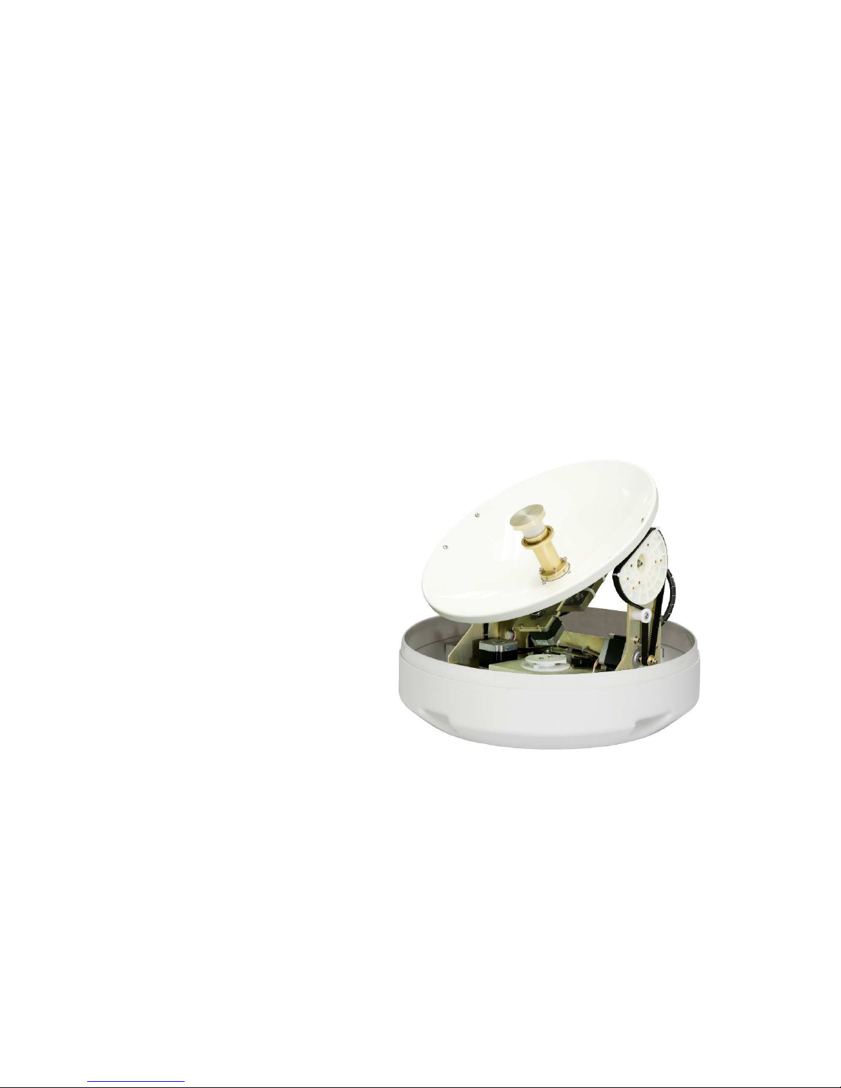
① ADU (Above Deck Unit)
- the stabilized platform: contains the majority of
hardware
- PCU (Pedestal Control Unit): controls electronics,
movement system, and RF equipment
- RF Unit: receives optimum satellite signal from the
satellite
- Radome: ultra-efficient plastic radome
provides minimal loss and protect from
marine environment
② BDU (Below Deck Unit)
- The BDU controls the
stabilized antenna and consists of the
UltraTrack TS-series interface (ACU)
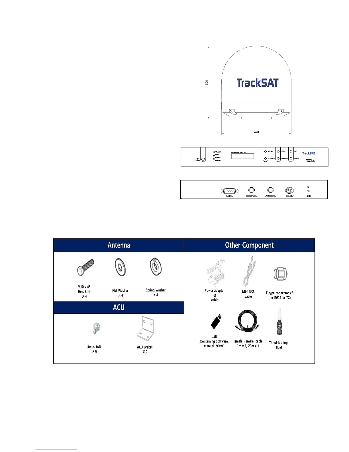
2.1.1 Installation Kit List
Figure 3 – Customer Kit List
Figure
1 - Radome
Figure
2 - KA78 ACU
3
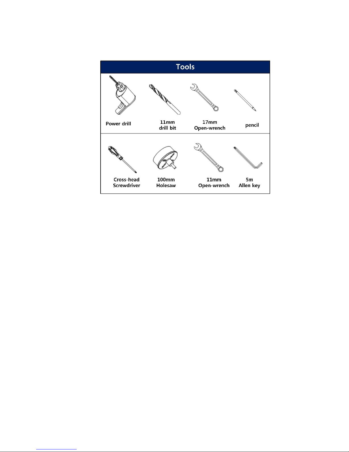
2.1.2 Required Tools
Figure 4 – Required Tools
2.2 Safety Precaution
ADU module is sealed unit. This unit should be closed under any circumstances.
The antenna radome assembly should be rigidly mounted on the boat. If necessary,
reinforce the mounting area to assure that it does not flex due to the boat’s motion or
vibration.
Environmental: must operate in controlled environment (temp, altitude, dust, vibration,
corrosive, explosive free)
EMC (elective magnetic compatibility): to ensure the antenna system provides the highest
protection against interfering. The antenna should be in front of a radar beam.
Cable must be shielded and all equipment must be covered
During the lifting, the system has to be balanced. Swaying or dropping the radome
assembly may cause personnel injury or damage to the system.
4
2.3. Unpacking
① Place the shipping box on a rigid, leveled surface.
② Inspect shipping box and note any damage.
③ Lift the unit out of the crate carefully
④ Move the antenna to its operating location (Using great care)
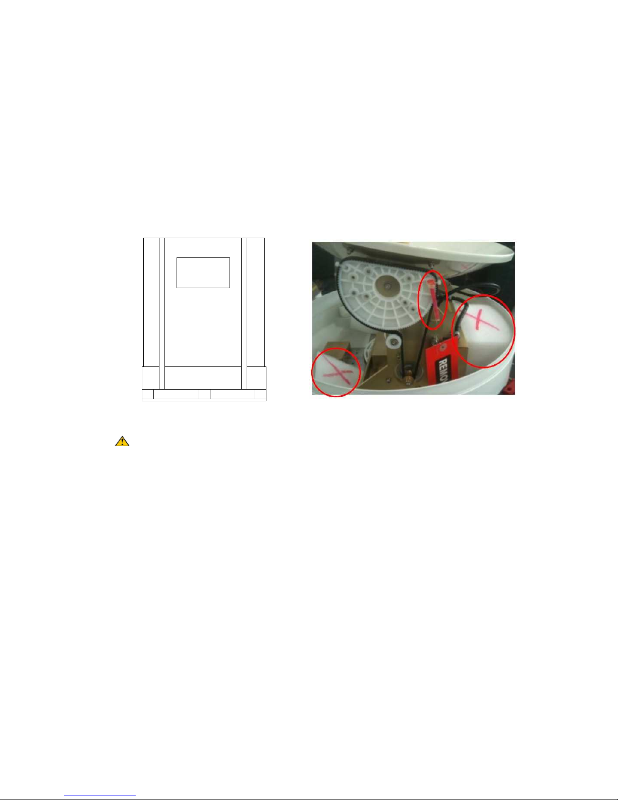
⑤ When you have the antenna in its permanent location, remove the securing materials (zip-
tie, shipping foams and fixed bolt) which keeps the antenna from free moving while in
transit.
Warning:
- Do not turn the box upside down and roll, it may cause the damage to the antenna.
- Always lift the antenna unit by the baseplate to avoid damage.
- Do not supply the power before removing the securing materials. It may cause the damage
to the system.
- When the antenna needs to be relocated, the securing material must be re-installed to
prevent damage from free moving while in transit.
2.4 Selecting Installation Site
The following should be kept in mind when selecting a physical location on the vessel for the
antenna equipment:
2.4.1 ADU (Above deck Unit: antenna Unit)
① Visibility: the TS39 needs clear line of sight to the satellite for the most vessel heading.
Choose a location where masts or other structures do not block the satellite signal from
the dish as the boat turns.
② Vibration: high vibration will effect in reducing its performance. Choose a location a far
Figure 5
- Shipping box
Figur
e 6 -
Shipping constrains

5
from vibrating equipment as possible.
③ Cable runs: locating the ADU close to the radio room creates much easier installation.
④ Interference: the antenna should be installed in the beam of other transmitting antenna
which may generate signals with the potential to interfere. The further away the UltraTrack
TS series antenna is from these other antennas, the less likely is it to be affected by their
operation.
⑤ Heat source: the antenna assembly unit has to be well away from engine (exhaust gas/
flare).
Figure 7 – Site Selection Example
2.4.2 BDU (Below deck Unit: ACU)
The ACU (Antenna Controller Unit) will arrive with the TrackSAT control software pre-installed
and will automatically run on the power up and also operation is largely automatic but it is
desirable that it be monitored periodically. Therefore, it is beneficial that it be sited in a location
with easy operator access.
ACU should be installed in a radio room where:
- In a cool and dry location
- In a place that not susceptible to magnetic interference LCD display is visible and the
buttons are easily accessible
2.5 Mounting and Installing the Antenna
Once antenna mounting site (on the power tower
or separate antenna post) is identified, make
mounting holes and cable access hole on the
mounting surface. (see Figure – 8 and Appendix F
- Mounting Hole Layout) and follow these steps
for proper installation.
Figure 8
– Mounting pattern
6
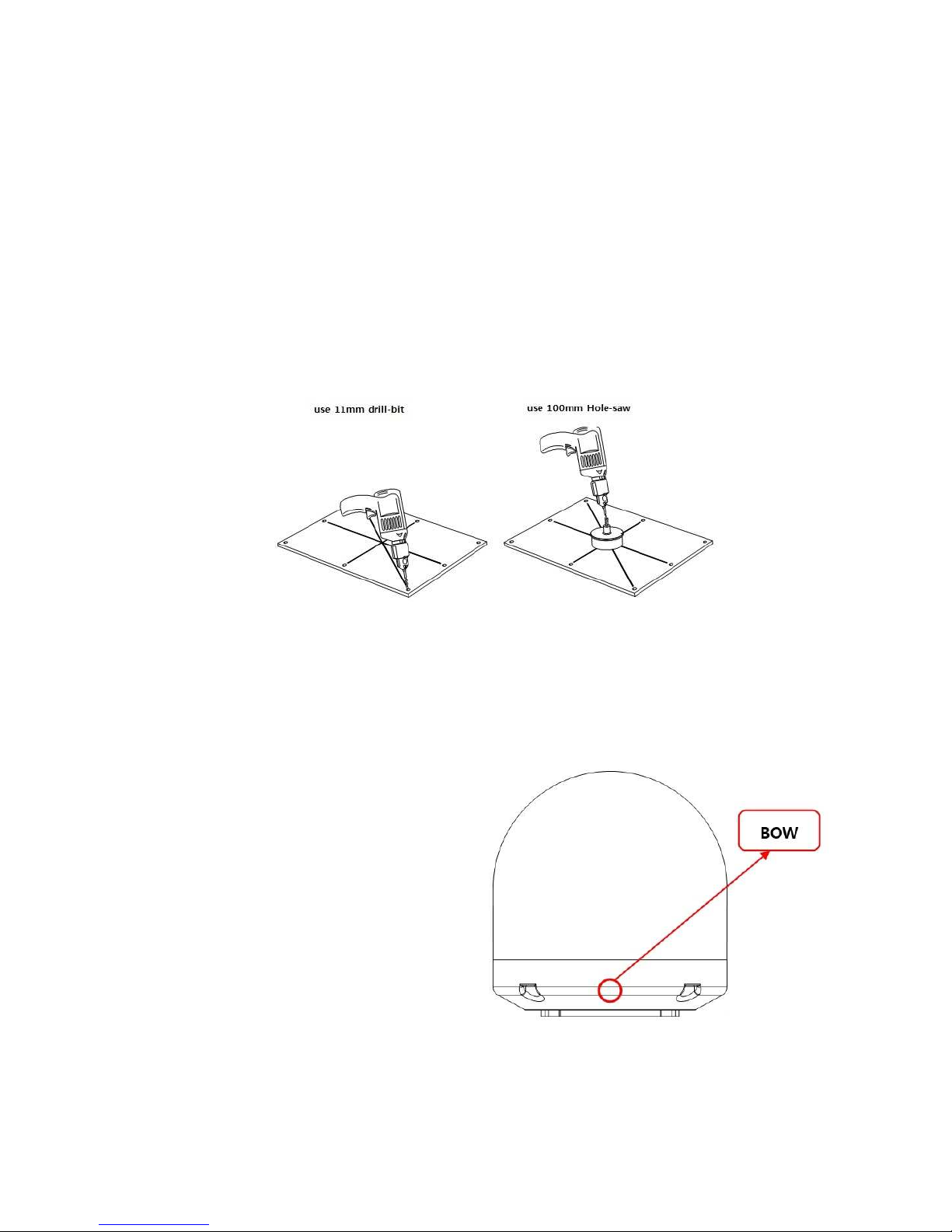
2.5.1 Preparing Mounting Surface
① Clean the surface where the antenna to be mounted
② Mark the 4 bolting holes position and center point for cables hole on the mounting surface.
(see Figure – 9)
③ Make 4 bolt holes on the surface by using the power drill with 11mm drill bit.
④ Make cable hole at the center position by using the power drill with 100mm hole-saw.
⑤ Remove sheet metal particle and clean the surface.
Figure 9 – Preparing the Mounting Surface
2.5.2 Installing the Antenna
① Lift the system onto its supporting post and position the antenna base plate in place in
position over the mounting holes and cable access.
② Ensure the radome is pointing correct
direction - align the BOW label on the
bottom plate with the ship’s bow and is
parallel to the vessel’s center line. (see
Figure – 10)
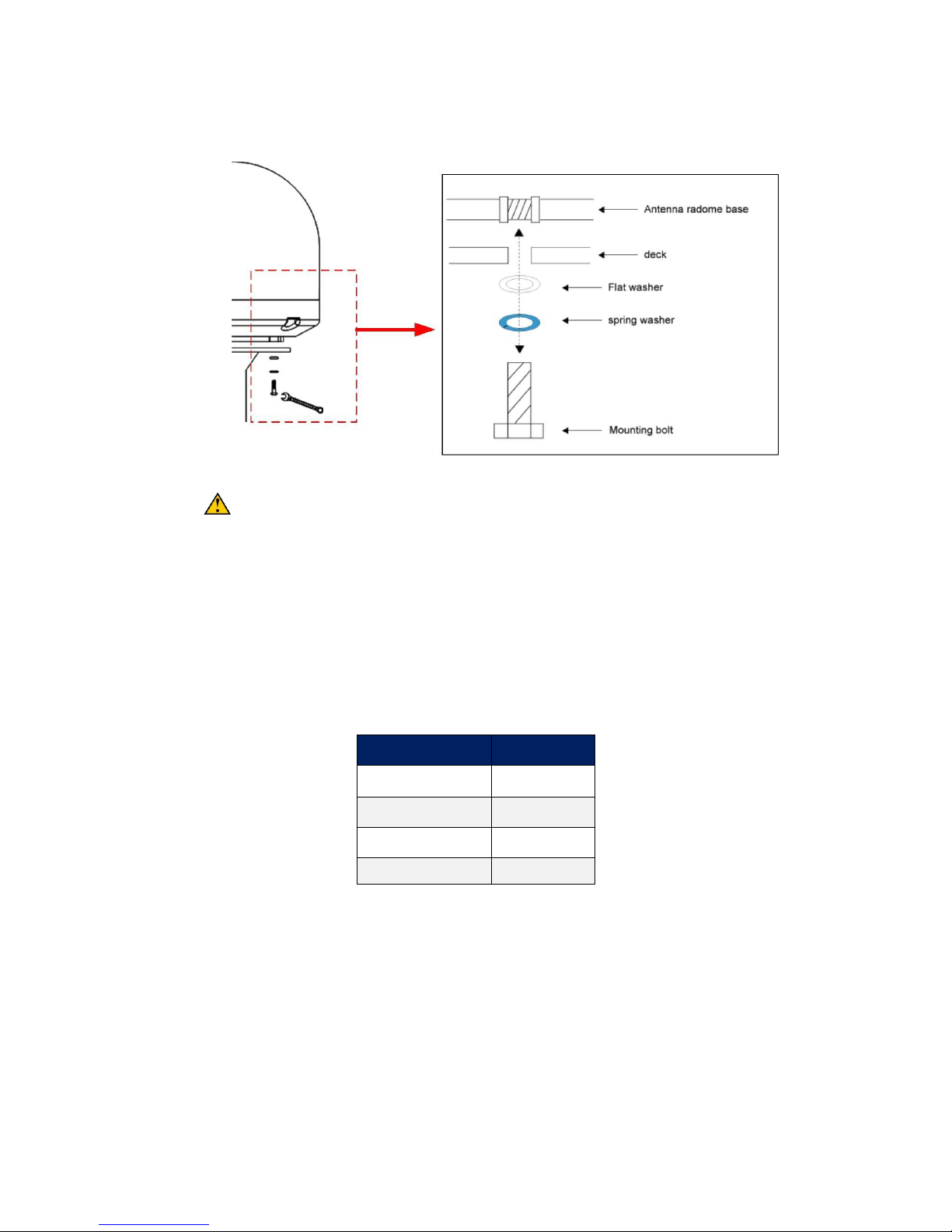
③ Insert the flat and spring washer and a
mounting bolt to each mounting holes
around the base plate of the radome.
(see Figure -11)
④ Apply Loctite to the threads of the
mounting bolt up near the mounting
surface and tighten each 4 bolts to 20
lb-ft (27 N-m) torque [use an 17mm socket or open-end wrench]. (see Figure – 11)
Figure 10
– Radome Bow Mark
7
Figure 11 – Securing the Antenna
Do not over-tighten. If the mounting bolt provided is too short, you will have to
install mounting bolts of the appropriate length. If the bolt provided is too long, the
excessive length should be cut off.
2.6 ADU Cable Connection
Before starting the electric connection task, find the suitable location for laying the cables from
BDU to ADU. The antenna cable must be connected to the ACU (Antenna Control Unit) and the
antenna unit. Follow the steps below.
① Determine the type of cable to be used depends on the cable length required. (see Table
– 1)
② Bring the RF cables (with F-male type connector) from BDU (Below Deck Unit) up through
the cable access hole.
③ Lay the cables through the waterproof fittings and close with sealing material to avoid
water penetrating.
Cable Length Cable Type
Within 20m RG6
Within 50m RG11
Within 100 LMR 400
Within 200m LMR 600
Table
1 – RF Cable Guideline
 Loading...